Get Repair Quote
Name
Company *
Phone *
Email *
Address
City
State / Province / Region
Zipcode
Country
Quantity *
Part Number *
Manufacturer
Preferred Condition
Additional Information
Cancel

IC694ALG391

Output module analog 2 points, current.
In Stock

Product Information:

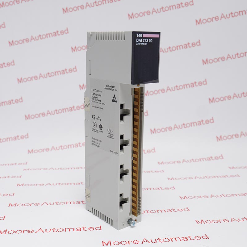
2–Channel Analog Current Output module
has two output channels
each capable of converting 12 bits of binary (digital) 
data to an analog output signal for field devices
The module’s outputs can be set up to either 
Default to 0/4 mA or Hold–Last–State
Expand All
Collapse all

Technical specifications for IC694ALG391

  • Manufacturer:
    General Electric
  • Product Category:
    PLC System
  • Estimated shipping dimensions:
    3.5x13.2x13.5cm
  • Weight:
    0.34 kg
  • Tariff Code:
    8537101190
  • Country of origin:
    USA
  • Place of shipment:
    Xiamen, Fujian, China
  • Output Current Range:
    4 to 20 mA and 0 to 20 mA
  • Output Voltage Range:
    1 to 5 volts and 0 to 5 volts
  • Calibration:
    Factory calibrated to 4 µA per count
  • External Supply Voltage Range:
    20 VDC to 30 VDC. Depends on the current load and the ambient temperature as shown below.
  • Maximum Compliance Voltage:
    25 VDC
  • Stock:
    40

Ask our team:

  • What intrinsic functional purpose does the IC694ALG391 serve within a PACSystems RX3i or Series 90‑30 control infrastructure?
    The IC694ALG391 is a precision analog current output module designed to convert 12‑bit digital values from a PLC into accurate industrial analog outputs for actuators, variable speed drives, and field instruments.
  • How does the IC694ALG391 accommodate configurable output ranges, and what implications does this have for system flexibility?
    Each channel of the IC694ALG391 can be jumper‑configured for either 0‑20 mA or 4‑20 mA current ranges, allowing engineering flexibility in mapping analog outputs to a wide spectrum of sensor and control device requirements.
  • What is the resolution and update cadence intrinsic to the IC694ALG391’s D/A conversion process?
    The IC694ALG391 implements a 12‑bit digital‑to‑analog conversion with typical update rates around 5 milliseconds per channel, enabling relatively high‑fidelity signal generation in dynamic automation tasks.
  • Under what circumstances can the IC694ALG391 provide voltage outputs, and how is this configured?
    Although primarily a current output module, the IC694ALG391 can be configured for voltage outputs (e.g., 1‑5 V or 0‑5 V) by placing a 250 Ω resistor in place of the current jumper on the terminal block, increasing its utility in certain analog interfacing scenarios
  • What isolation mechanisms are embodied in the IC694ALG391 to safeguard signal integrity and electrical separation?
    The IC694ALG391 incorporates optical isolation between the field I/O and backplane logic, providing robust electrical decoupling and minimizing noise coupling from industrial plant power systems.
  • What power supply requirements must be met for stable operation of the IC694ALG391?
    The IC694ALG391 requires a regulated +5 VDC for internal logic and an isolated +24 VDC external supply to drive the analog current loops, ensuring sufficient headroom for both module electronics and field load requirements.
  • How does the IC694ALG391 determine its default output state during CPU stop conditions, and what configuration options control this behavior?
    The output behavior of IC694ALG391 upon PLC stop or reset is jumper‑selectable; it can either default to 0/4 mA or retain the last valid analog value depending on the jumper setting on the detachable terminal board.
Quantity
Upload
(gif, jpg, jpeg, png, bmp, doc, docx, xls, xlsx, ppt, pdf, csv)
For more information on how your data is processed and stored by Moore automated please read our privacy policy.
Trusted by 5,000+ plants worldwide | Backed by our vast inventory of top-tier control parts, drives and servo motors, fast shipments are dispatched to cover your urgent needs. ABOUT US >>
Moore Disclaimer: Moore Automated's sales automation equipment and related solutions are intended for industrial automation and business operational efficiency improvement purposes only. Product information, technical parameters, and application cases are for reference only and do not constitute an absolute guarantee of performance for any specific industry, scenario, or final application. Actual equipment performance may vary depending on factors such as the usage environment, system integration method, and maintenance conditions. Users should confirm compatibility and safety based on professional technical assessments. Moore Automated assumes no liability for any direct or indirect losses caused by improper use, modification, or failure to operate according to specifications, to the extent permitted by law.