Get Repair Quote
Name
Company *
Phone *
Email *
Address
City
State / Province / Region
Zipcode
Country
Quantity *
Part Number *
Manufacturer
Preferred Condition
Additional Information
Cancel

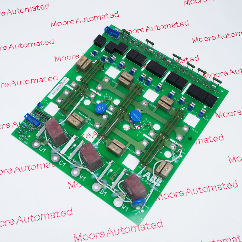
SDCS-PIN-4

Power Interface Board
In Stock

Product Information:

DCS880 Interface Board

Power Interface Board

Plug in options and DCS800

Control Panel

Expand All
Collapse all

Technical specifications for SDCS-PIN-4

  • Manufacturer:
    ABB
  • Product Category:
    DCS System
  • Spare Part Number:
    3ADT314100R1001
  • Estimated shipping dimensions:
    25x22.5x5.5cm
  • Weight:
    0.82 kg
  • Tariff Code:
    8537101190
  • Country of origin:
    sweden
  • Place of shipment:
    Xiamen, Fujian, China
  • Product Type:
    Power Interface Board
  • Category Series:
    DCS 800
  • Voltage Supply:
    24 V DC
  • Current consumption:
    4-20 mA
  • Frequency response:
    50/60 Hz ± 5 Hz
  • Operating Temperature:
    -20 °C to 55 °C
  • IP degree of protection:
    IP 20
  • Stock:
    30

Information

Overview Manuals Principle Primary Functions and Applications

Features:

  • DCS880 Power Interface board
  • Plug in options and DCS800 Control Panel
  • It serves as a crucial bridge between the power electronics components of the driver and the SDCS-CON-4 control board
It is typically used in DC or AC drive control platforms to connect and convert signals between the control unit and the field. This module plays a crucial signal interface role in the system, receiving measurement signals or control commands from the field and converting them into standardized signals that the control system can recognize and process, thereby supporting the stable operation and precise control of the drive system.

At the system application level, the SDCS-PIN-4 provides reliable electrical isolation and interference immunity, maintaining stable signal transmission even in complex industrial electromagnetic environments. The module connects to the drive control unit via a standard interface, supporting system expansion and maintenance, and improving the reliability and maintainability of the entire drive system in industrial applications.

The SDCS-PIN-4 ABB Power Interface Board may still be available for purchase and support from Moore Automated Company beyond End-Of-Life (EOL) by the manufacturer (OEM).
ABB SDCS-PIN-4 Power Interface Board Manuals(Datasheets), Link Important Notice: Other accessories, manuals, cables, calibration data, software, etc. are not included with this equipment unless listed in the above stock item description. All prices are shown in USD.
In terms of operating principle, the SDCS-PIN-4 utilizes internal signal conditioning circuitry to filter, isolate, and level-match input signals. Voltage or current signals acquired from the field first pass through protection and filtering circuits, then through isolation and conversion circuits, and finally are transmitted to the control system. This allows the control unit to perform real-time calculations and control decisions based on the processed signals, thereby achieving stable control of the motor or drive equipment.
The SDCS-PIN-4 module monitors and protects drive systems through the following key hardware functions:
 
  1. Voltage Measurement: Provides high-impedance measurement of DC and AC voltages, ensuring a stable power supply.
  2. Current Sensing: Serves as an interface to current transformers, measuring armature current to enable precise torque and speed regulation by the driver.
  3. Thyristor Protection: Integrates a snubber circuit to protect the driver's thyristors from voltage spikes and rapid electric field changes.
  4. Temperature Monitoring: Connects to a PTC resistor to monitor heatsink temperature, preventing overheating and potential component failure.
  5. Signal Isolation: Protects sensitive control circuitry from surges or faults in industrial environments through isolation and protection.


Ask our team:

  • How does SDCS-PIN-4 meet the electrical interface requirements and signal integrity constraints defined in the datasheet?
    SDCS-PIN-4 operates within specified voltage, current, and isolation ranges to ensure reliable signal transmission and compatibility with relevant control electronics in industrial environments.
  • According to its technical documentation, what input/output signal conditioning methods and circuit protection strategies are employed in SDCS-PIN-4?
    SDCS-PIN-4 integrates filtering, isolation, and protection circuitry designed to stabilize signal acquisition and protect connected subsystems from electrical interference.
  • Which environmental certification parameters and operational endurance thresholds of SDCS-PIN-4 are certified?
    The SDCS-PIN-4 is designed for reliable operation in industrial environments, including temperature variations, electromagnetic interference (EMI), and vibration exposure. Please refer to its datasheet for details.
  • Which system interoperability standards and integration protocols does the SDCS-PIN-4 support?
    The SDCS-PIN-4 is designed for seamless connectivity with compatible industrial drive controllers and automation systems, supporting standardized electrical and communication interfaces.
  • How does the SDCS-PIN-4 maintain functional stability under transient electrical disturbances and dynamic load conditions?
    The SDCS-PIN-4 employs a protection circuit design and signal stabilization technology to maintain stable operation during voltage fluctuations and transient events.
Quantity
Upload
(gif, jpg, jpeg, png, bmp, doc, docx, xls, xlsx, ppt, pdf, csv)
For more information on how your data is processed and stored by Moore automated please read our privacy policy.
Trusted by 5,000+ plants worldwide | Backed by our vast inventory of top-tier control parts, drives and servo motors, fast shipments are dispatched to cover your urgent needs. ABOUT US >>
Moore Disclaimer: Moore Automated's sales automation equipment and related solutions are intended for industrial automation and business operational efficiency improvement purposes only. Product information, technical parameters, and application cases are for reference only and do not constitute an absolute guarantee of performance for any specific industry, scenario, or final application. Actual equipment performance may vary depending on factors such as the usage environment, system integration method, and maintenance conditions. Users should confirm compatibility and safety based on professional technical assessments. Moore Automated assumes no liability for any direct or indirect losses caused by improper use, modification, or failure to operate according to specifications, to the extent permitted by law.