Overview
Manuals
Technical & Electrical Characteristics
How It Works
Features:
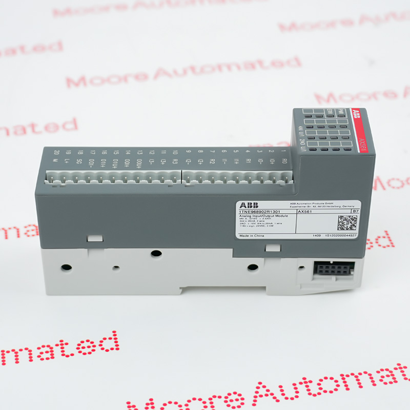
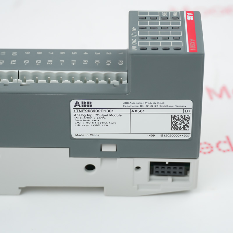
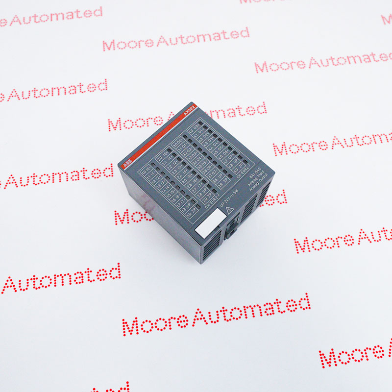
- AX561 S500 Analog input/output module. 4 AI: U, I. 2 AO: U, I. 1-wire
- Operates at 12-bit resolution for unipolar signals (or 11-bit + sign for bipolar voltage signals), ensuring precise data conversion
- It is used to process current and voltage process signals in industrial automation systems
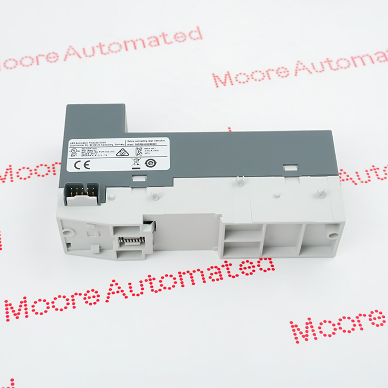
The ABB AX561 (order number: 1TNE968902R1301) is a highly integrated analog input/output expansion module in its AC500-eCo/S500-eCo series programmable logic controller (PLC) systems. This module is primarily used in industrial automation control systems to connect various field sensors and actuators. It integrates four independently configurable analog input channels (AI) and two analog output channels (AO) within a compact housing, directly processing voltage or current signals from the field to achieve efficient data acquisition and precise industrial data control.
In terms of functionality, its four analog input channels are highly flexible, supporting a variety of signal ranges, and can even be directly configured as digital inputs when necessary. Its two analog output channels are equally comprehensive, supporting 0...20mA and 4...20mA current signals as well as -10...+10V voltage signal outputs. The entire module features 12-bit (including sign bit) analog-to-digital/digital-to-analog conversion resolution and built-in hardware filters and overvoltage protection, providing a stable and interference-resistant data interface in complex industrial electromagnetic environments.
The AX561 1TNE968902R1301 ABB PLC Analog Input/Output Module may still be available for purchase and support from Moore Automated Company beyond End-Of-Life (EOL) by the manufacturer (OEM).
ABB AX561 1TNE968902R1301 PLC Analog Input/Output Module MANUAL(Datasheets), Link
Important Notice: Other accessories, manuals, cables, calibration data, software, etc. are not included with this equipment unless listed in the above stock item description. All prices are shown in USD.
Supply Voltage: Powered via a nominal 24 V DC internal bus system.
Wiring: Offers two-wire input and single-wire output configurations via detachable terminal blocks (e.g., TA563 or TA564 front panel connectors).
Conversion Time: Typical analog-to-digital conversion time is 500 µs per channel.
Input Resistance: Voltage setting greater than 1 MΩ, current loop approximately 250 Ω.
Hardware Protection: Built-in short-circuit protection, reverse polarity protection, and transient overvoltage protection up to 30 V DC.
Enclosure: Compact enclosure with IP20 protection rating for standard 35 mm DIN rail mounting.
The AX561 module primarily operates based on a data bridging mechanism between an analog-to-digital converter (ADC) and a digital-to-analog converter (DAC). At the input, continuous analog electrical signals generated by field sensors (such as the 4-20mA current output of a pressure transmitter) are fed differentially into the input channels.
After internal hardware filters eliminate high-frequency noise, the built-in ADC converts these signals into 12-bit digital values (hexadecimal codes), with a conversion time of approximately 500µs per channel. This data is then transmitted in real-time to the PLC host for logic operations via the I/O bus. At the output, the PLC host sends digital control commands to the module via the I/O bus.
The internal DAC converts these digital signals back into precise analog voltage or current signals, directly driving external actuators such as proportional valves, frequency converters, or regulating valves, thereby completing the entire closed-loop control process.