Overview
Manuals
System Installation and Parameter Setup
Replacement and Maintenance
Features:
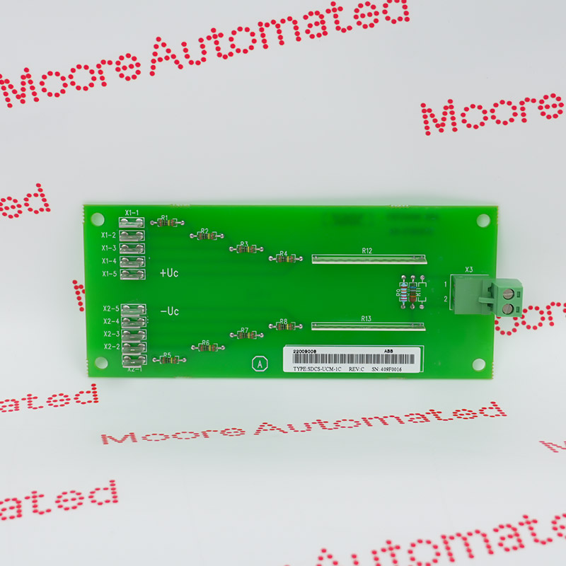
- Industrial external DC voltage measurement expansion board
- External Measurement Card / Isolated DC-DC Transducer Module
- Isolation Measurement Expansion Board / External DC Voltage Measurement Component
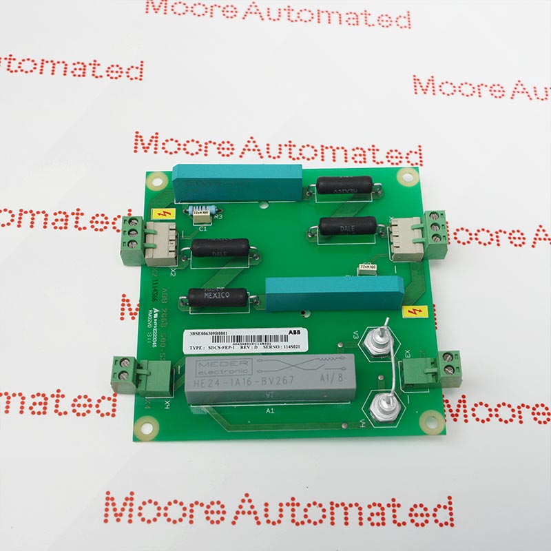
The main function of this module is to achieve safe isolation between the high-voltage DC side and the low-voltage control side, and to convert the dynamic high voltage of the motor armature circuit into an analog signal that can be directly read by the driver's main control board (such as SDCS-CON-2).
By accurately monitoring the DC motor's operating voltage, armature current, and temperature of key components in real time, it provides core feedback data support for the entire drive system. As a crucial front-end component of the DC drive control loop, this board possesses excellent high-voltage isolation protection and hardware fault detection capabilities.
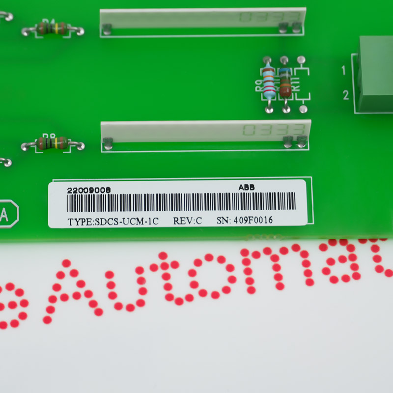
The SDCS-UCM-1C 3ADT220090R0008 ABB Excitation Board may still be available for purchase and support from Moore Automated Company beyond End-Of-Life (EOL) by the manufacturer (OEM).
ABB SDCS-UCM-1C 3ADT220090R0008 Excitation Board maunal(Datasheets), Link
Important Notice: Other accessories, manuals, cables, calibration data, software, etc. are not included with this equipment unless listed in the above stock item description. All prices are shown in USD.
When integrating the SDCS-UCM-1C board into your active drive system, you must use a software tool (such as DriveWindow) to adjust the internal firmware parameters to switch the control processor from structural calculation to direct analog pin tracking:
1.Navigate to parameter group 95 (Hardware Options).
2.Locate the sub-parameter specified for DC voltage measurement mode (typically parameter 95.37).
3.Change the feedback source parameters to activate external monitoring via the SDCS-UCM-01/DC-DC converter.
Dangerous Voltage: This board is directly connected to the DC main circuit or the armature voltage side of the motor, carrying a lethal DC high voltage. Before disassembling, adjusting, or replacing, the governor's incoming circuit breaker must be completely disconnected and tested for voltage, waiting at least 5 minutes to allow the internal capacitors to fully discharge.
Channel and Parameter Matching: After replacing this board, the feedback source parameter settings in the control system (such as DCS800) need to be checked to ensure that the system's voltage feedback channel (changed from the original internal estimate to the external actual channel input) is correctly matched.