


MP 3009X
Get A Quote
Communication loss in a distributed control system is never just an IT nuisanceŌĆöit is a process risk that can cascade into lost product, nuisance trips, and safety concerns. From plant floors to control rooms, IŌĆÖve chased intermittent timeouts, ŌĆ£staleŌĆØ values, and mysterious red X icons enough times to know that solving ABB DCS communication outages demands disciplined basics, quick signal intelligence, and calm, methodical isolation. This article distills a fieldŌĆætested approach tailored to ABB environments such as 800xA with AC 800M and CI-series communication modules, grounded in reputable guidance and onŌĆæsite experience.
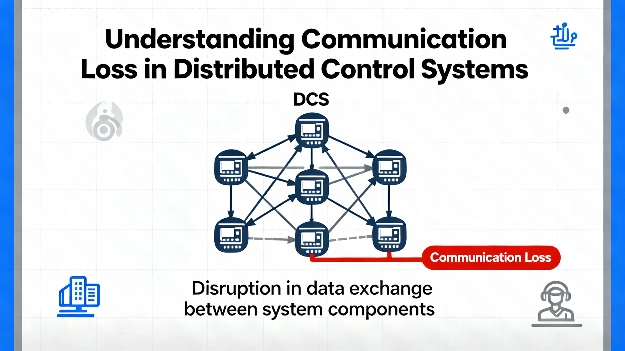
In simple terms, a Distributed Control System is a plantŌĆæwide control architecture where controllers, I/O, HMIs, servers, and networks coordinate to run continuous and batch processes. The DCS aims for minuteŌĆætoŌĆæminute determinism and consistency: process temperatures held within about ┬▒4┬░F, pressure sensing at roughly 0.1 psi resolution, and alarm handling on the order of hundreds of milliseconds. When the wires or packets that stitch this nervous system together falter, control loops degrade, operator situational awareness erodes, and protective functions may be compromised.
On ABB platforms, ŌĆ£communication lossŌĆØ can involve several layers. It may occur on serial and fieldbus links hanging off communication interface modules such as CI853. It can also happen on Ethernet segments between controllers, servers, and HMIs, or within switchŌĆætoŌĆæswitch paths where configuration drift, storms, or redundant path failures show up as latency, drops, or flapping routes. While root causes varyŌĆöhardware faults, congestion, configuration mistakes, software defects, or environmental interferenceŌĆöthe resolution begins the same way: verify the physical layer, validate addressing and protocol settings, collect useful diagnostics, and isolate until you identify the failing segment.
Loss of communications seldom announces itself politely. In the control room you may see device icons gray out, values freeze, or operator faceplates report ŌĆ£bad quality.ŌĆØ Controllers may log error codes; communication blocks in Function Block Diagram view show invalid or timedŌĆæout status. On a serial trunk, a converter might blink its Rx LED repeatedly while the partner device barely responds. The first question is whether the master is transmitting at all, and whether any slave is acknowledging.
For ABB CI853 serial masters, remember a basic serial truth discussed by practitioners on the Control.com forum: there is no line activity unless the master initiates it. If the Rx LED on your RSŌĆæ232/RSŌĆæ485 converter is blinking but you never see meaningful responses, it often indicates the master is talking while the slave is not acknowledging. In 800xA, confirm that the communication function block is enabled and ŌĆ£valid,ŌĆØ and retrieve the exact error codes from the block or the module diagnostics to consult vendor help.
A quick but safe field move is to connect a laptop to the master side with a proper programming cable and a terminal program, solely for observing whether transmit frames are leaving on schedule. This is a diagnostic check, not a permanent coupler. Use manufacturerŌĆæspecified cables; ABB cable part differences such as TKŌĆæ212 versus TKŌĆæ212A matter. Improvised pinouts from memory are a common source of silent failures.
| Symptom in plant | Likely cause | First onŌĆæsite check |
|---|---|---|
| Fieldbus values freeze or show bad quality on multiple nodes | Miswired or un-terminated serial trunk, wrong speed/parity, duplicate device addressing, or slave offline | Verify the CI853 comm block is enabled and valid, confirm Rx/Tx activity pattern, check termination and polarity on RSŌĆæ485, and match baud/parity/stop settings |
| Intermittent timeouts on a specific device | Loose connector, EMI coupling, localized hardware degradation | Reseat and inspect connectors, inspect shielding and ground, reroute cable away from highŌĆænoise conductors, and trend error counters |
| ControllerŌĆætoŌĆæHMI lag or stale faceplates during peaks | Network congestion or misconfigured switch path | Review switch port counters and logs, check for high utilization or discards, and validate QoS and traffic segmentation for critical control flows |
| Redundant path failover causes alarm storms | Asymmetric configuration or link health mismatch | Test redundancy switchover during a planned window, compare configs, and correct mismatched parameters |
| Converter shows Rx flashing without coherent responses | Master poll with no slave reply, incorrect addressing or handshaking | Confirm device address and protocol role, check CTS/RTS needs, and verify correct cable type for task |

Industrial communications fail for a handful of recurring reasons. Hardware faults do happenŌĆöbad ports, tired transceivers, damaged connectors, or a failing communication module. Networks become congested, especially when unbounded polling or diagnostic floods saturate switches that were never tuned for transient traffic. Configuration errors range from innocent parity mismatches and offŌĆæbyŌĆæone addresses to entire networks built on a misread wiring diagram. Software defects and regressions after upgrades surface particularly when crossŌĆæteam changes overlap. Environmental factors such as electromagnetic interference, temperature, and vibration stress connectors and degrade link integrity. Reputable industry guidance emphasizes watching these categories and not fixating on any single culprit.
Serial and fieldbus segments remain widely used in ABB systems. The CI853 acts as the master; by design the master controls the conversation rhythm. A few pragmatic checks shorten diagnosis.
Start by verifying the master is actually polling. In 800xA, confirm the function block that owns the link is enabled and shows a valid connection, then check module and controller logs for error codes and timeouts. Watch the Tx/Rx indicators at the CI853 and converter. Repeated Rx flashes on the converter with no corresponding valid responses often mean the slave isnŌĆÖt replying; dig into addressing, slave power and health, and protocol settings.
Do not underestimate cabling. Use the manufacturerŌĆÖs programming or communication cable for tasks that require it, such as TKŌĆæ212 versus TKŌĆæ212A. Many ŌĆ£works on paperŌĆØ cables fail because a single handshaking pin or polarity is flipped. Even when a DYI cable seems to pass a bench test, it may fall apart under plant noise, temperature, or movement. If a deviceŌĆÖs manual states CTS/RTS is required, honor it; some converters mask handshaking errors until the line is under load.
Avoid the seductive detour of ŌĆ£just upgrade the controllerŌĆØ midŌĆæincident. Upgrades rarely fix a wiring, termination, or address problem and can delay a straightforward resolution. When needed, test software changes in an offline or staging environment first, then deploy during a maintenance window with a rollback plan.
Ethernet plant networks are fast and flexible, but they need discipline. Topology drift, unmanaged redundancy, and heavy diagnostic traffic can create symptoms that look like device failures. The remedy is structured observation and clear separation of critical traffic from everything else.
Validate the intended topology. Physically trace the path and compare it to the documented design, then reconcile any field changes that never made it into drawings. Managed switches are your friendsŌĆöpull port error counters and logs to find the sites of congestion, discards, or link flaps. Quality of service and segmentation are not buzzwords in control plants; they keep safety and control traffic flowing predictably when less critical services spike.
When a redundant path exists, test it. Silent divergence in configuration between primary and secondary links produces chaotic behavior when a switchover occurs. Run a planned failover test, watch alarms and counters, and align the configs if behavior differs during the transition.
On the plant floor, the playbook is layered and linear. Begin at the physical layer, because it is fast to verify and fails more often than we like to admit. Check power, grounding, environmental conditions, and cable routing. Pay attention to where control wiring shares trays with motor feeders or VFD outputs; reroute or shield where appropriate to shrink EMI coupling.
Shift to wiring integrity. Confirm the cable type and length are suitable, inspect terminations and shields, and reseat connectors. On RSŌĆæ485, verify polarity and ensure termination only at segment ends. On serial trunks, watch for duplicated device addresses or misapplied parity and stop bit settings. For Ethernet, validate port assignments, VLAN or other segmentation boundaries, and that any mirrored or spanned ports are correctly configured for diagnostics, not for control traffic.
Confirm configuration. Device addresses must be unique and consistent endŌĆætoŌĆæend. For serial masters, match baud, parity, and stop bits across the trunk. For Ethernet devices, ensure IP addressing and subnets align with the documented plan. In ABB engineering tools, verify communication block parameters and that the blockŌĆÖs health status genuinely reflects what you see in the field.
Exploit diagnostics. Controllers, communication modules, and switches provide logs and counters that reveal trends long before a blackout. Error counters, token or packet statistics, and CRC counts highlight whether the line is clean or just barely hanging on. Vendor diagnostics often include highŌĆævalue summaries that point to wiring reversals, baud mismatches, or addressing conflicts without forcing you to interpret every counter by hand. Use them early to narrow the search.
Isolate deliberately. Segment the network to a minimal configuration that still shows the fault, or replace a suspected component with a knownŌĆægood spare. A short pointŌĆætoŌĆæpoint test between master and a single slave is often decisive. When a suspected port or module is removed from the equation, either the problem travels with it or it stays put.
Document and stabilize. Every corrective action deserves a short entry in a troubleshooting log, including the observed symptom, the change you made, and the result. This habit shortens future incidents, supports preventive maintenance, and speeds vendor escalations.
What looks like ŌĆ£just a network glitchŌĆØ can be a security or architectural issue. Modern DCS environments are increasingly connected to enterprise systems, analytics, and cloud tools. The result is a broader attack surface and a richer set of ways for performance to degrade when integration is not governed carefully.
Reputable industry guidance from the ISA Global Cybersecurity Alliance advocates an inventory of every device and interface, followed by segmentation into logical zones with controlled conduits. This approach contains faults and prevents nonessential traffic from swamping control paths. Legacy operating systems and mixed vintages introduce fragility; they are not only a cyber risk, but also a practical barrier to timely patching and consistent configuration. A riskŌĆæbased, staged improvement plan aligns mitigation cost with the criticality of the process.
Comparative analysis in Industrial Cyber underscores that plantŌĆælocalized DCS has historically enjoyed more centralized management than wideŌĆæarea SCADA. Even so, modern DCS integrations with enterprise tools expand exposure; the takeaway is to apply strong segmentation and disciplined change control in both worlds.
Reliability is designed, not hoped for. Routine inspections catch loosening terminals, clogged filters, and creeping EMI issues before they become outages. Maintaining software currency, with updates tested offline and deployed during windows with planned rollbacks, reduces regression surprises. Trending key diagnosticsŌĆöcommunication error counts, controller CPU load, and redundant link switchover eventsŌĆöyields early warnings you can act on. Staff training and clear operating procedures shorten alarm response and reduce operatorŌĆæinduced configuration errors. A living spares plan keeps the right parts on the shelf so that isolation by substitution is a tenŌĆæminute test rather than a week of procurement.
Every plant is different, but several buying and stocking practices pay off across ABB fleets. Use vendorŌĆæsupplied programming and communication cables for configuration and diagnostics. Differences between ABB cable variants such as TKŌĆæ212 and TKŌĆæ212A are not cosmetic; they matter electrically and mechanically. Keep a knownŌĆægood programming cable stored where anyone on shift can find it.
Stock essential spares in categories that history has proven timeŌĆæcritical: communication interface modules, a handful of the most common I/O modules, power supplies that have a long lead time, and communication interface options such as fieldbus adapters where applicable. For ABB ecosystems, spare coverage for modules like CI853 for serial and fieldbus, AI810 for analog inputs, and FIŌĆæseries fieldbus cards has proven practical in many plants. Keep a reliable RSŌĆæ232/RSŌĆæ485 converter that supports hardware handshaking, and label it as tested. For Ethernet, standardize on managed industrial switches that provide meaningful diagnostics and consistent tooling across the site. Choose test tools with care: a quality multimeter, a scope for stubborn noise cases, and software utilities that can read controller logs and network health are small investments that pay back the first time a nightŌĆæshift outage is cut from hours to minutes.
Finally, invest in documentation and training alongside hardware. A wiring diagram and a trunkŌĆætopology sketch that reflect the real plant, not the original bid package, are worth as much as a spare module when you are troubleshooting at 3:00 AM.

| Layer | What to verify | Useful evidence |
|---|---|---|
| Power and environment | Stable supply, correct grounding, acceptable cabinet temperature and airflow | Power measurements, cabinet inspection, temperature trend, UPS status |
| Physical media | Cable type and length, terminations, shield continuity, connector integrity | Visual inspection, continuity tests, reseat and retorque results |
| Addressing and protocol | Unique device addresses, correct baud/parity/stop bits, or correct network segmentation | Configuration screenshots, device label checks, block status in engineering tools |
| Network load and health | Utilization, discards, errors, storm events, consistent redundancy behavior | Switch port counters and logs, planned switchover test observations |
| Device and software | Firmware and options alignment, recent change history, error codes | Change log entries, module diagnostics, vendor help crossŌĆæreferences |
ItŌĆÖs tempting to treat serial, fieldbus, and Ethernet as interchangeable pipes. In practice, they differ in speed, determinism, and diagnostics. Serial and traditional fieldbus links are simple and predictable when wiring and termination are correct; they also tend to expose addressing and parity mistakes immediately. Ethernet provides bandwidth and flexible topology but requires intentional design to keep noisy or bulky traffic away from critical control flows. Operationally, the right choice is built on process needs, lifecycle maturity, and the teamŌĆÖs capability to maintain the network. For many plants, a hybrid is sensible: keep local device networks simple and predictable, and use structured Ethernet for supervisory and plantŌĆælevel communication with clear segmentation.
Two patterns recur. The first is cable myopia: hours spent on software settings with a wiring reversal hiding in plain sight. The cure is to physically trace and verify polarity and terminations before diving deeper. The second is upgrade optimism: the belief that installing a new controller or patch during a live outage will resolve a communication fault. Upgrades deserve their own controlled window with offline testing and explicit rollback steps. When you apply these disciplinesŌĆöverify physical first, observe and trend, isolate by substitution, and document as you goŌĆöyou solve most communication outages without drama.
Communication reliability in an ABB DCS is a product of attention to fundamentals, honest diagnostics, and disciplined change management. Start with the master on serial and fieldbus links and verify that it is actually talking. Treat Ethernet as a managed, segmented utility rather than a convenience. Lean on the platformŌĆÖs diagnostics, test redundancy deliberately, and maintain spares and documentation that convert guesswork into measured action. When operations, maintenance, and engineering share the same playbook, communication loss becomes a fast, teachable incident rather than a shiftŌĆæending crisis.
Confirm the associated communication block in the engineering workstation is enabled and healthy, then observe Tx/Rx indicators at the CI853 and the converter. If you see the receive side blinking without meaningful responses, the master is likely polling and the slave is not replying. Verify addressing, baud and parity settings, and check the physical terminations and polarity.
It is possible but not recommended. ABB programming cables are designed for the task, and differences such as TKŌĆæ212 versus TKŌĆæ212A are significant. Improvised cables frequently fail due to wiring mistakes or missing handshaking, especially under plant conditions with EMI. Keep a vendorŌĆæsupplied cable on site and label it as a knownŌĆægood tool.
Avoid upgrades during an active outage unless vendor guidance explicitly ties the fault to a known, fixed defect. Many communication faults are wiring, configuration, or environmental issues. Test updates in a controlled environment, schedule deployment, and maintain a rollback path to protect production.
Use isolation and counters. Replace suspect segments with knownŌĆægood cables, move a device to a short pointŌĆætoŌĆæpoint test with the master, and observe whether errors follow the device. Pull switch port counters to see if the problem correlates with discards or errors on specific links. A problem that moves with the device likely indicates a device or configuration fault; a problem that stays tied to infrastructure points back to the network.
Keep at least one spare for critical communication interfaces, a small set of the most used I/O modules, and power supplies with long lead times. For ABB systems, spares for CIŌĆæseries communication modules, common analog input cards, and any fieldbus interface modules in service are prudent. Store a tested programming cable and a reliable RSŌĆæ232/RSŌĆæ485 converter that supports the required handshaking.
Integration with enterprise systems increases the attack surface and the potential for performance side effects from scanning, backups, or misrouted traffic. An asset inventory and network segmentation aligned with recognized industrial security standards reduce unplanned load and contain faults. In practice, good security hygiene reinforces communication reliability.
Control.com forum discussions on ABB 800xA serial communications present practical clues such as masterŌĆædriven traffic patterns and the importance of correct cabling and handshaking. ISA Global Cybersecurity Alliance guidance highlights inventory, segmentation, and defenseŌĆæinŌĆædepth as foundations for resilient DCS communications. Analyses in Industrial Cyber compare DCS and SCADA risk profiles and reinforce the need for disciplined integration. Practical troubleshooting themes from IDS Power and Jiwei Auto emphasize layered diagnosis, isolation by substitution, and preventive maintenance. Vendor tips from ABBŌĆÖs published communications and drives diagnostics underscore the value of builtŌĆæin counters and targeted parameters to triangulate faults efficiently. Smart ElemechŌĆÖs operations advice reinforces power, EMI, firmware hygiene, and the value of shielded cabling across ABB components.


Copyright Notice © 2026 mooreautomated.com All rights reserved,Moore Automated is not an authorized distributor or representative of the manufacturers featured on this website. Brand names and trademarks featured are the property of their respective owners.


Leave Your Comment