


MP 3009X
Get A Quote
As an industrial automation engineer who spends a lot of time commissioning loops on noisy factory floors, I choose analog input modules by how well they measure the truth and how reliably they keep measuring it once the drives, heaters, and valves around them wake up. Accuracy and noise immunity are two sides of the same coin. A module that resolves microvolts on paper but folds under ground loops or radiated bursts will cost you hours of troubleshooting and unstable control. This guide compares practical options, explains the knobs that really move accuracy and noise immunity, and closes with scenarioŌĆæbased recommendations you can apply on your next project.
Accuracy in this context is the total measurement error across conditions you actually run, not just converter bit depth. Practitioners know resolution is only the first rung on the ladder. Accuracy includes gain and offset error, nonlinearity, temperature drift, and noise floor. Reputable sources distinguish between bit depth on the data sheet and total unadjusted error over temperature. In a closed loop, accuracy shows up as tighter setpoint tracking, cleaner disturbance rejection, and less controller overŌĆæeffort after tuning.
Noise immunity is the moduleŌĆÖs ability to deliver a stable, truthful value in the presence of coupling and interference you do not control. Factory floors inject conducted and radiated disturbances, line frequency hum, ground potential differences, and wiringŌĆæinduced crosstalk. Modules that break ground loops, reject line harmonics, and flag wiring faults keep loops trustworthy. From a control perspective, noise immunity preserves signalŌĆætoŌĆænoise ratio so your PID derivative term does not amplify junk and your antiŌĆæwindup does not chase ghosts.
Guidance from control engineering fundamentals emphasizes sampling and filtering choices that match the process. A sensible starting point is to sample five to ten times faster than the dominant process dynamics, and to apply appropriate measurement filtering so controller bandwidth is not poisoned by noise. This aligns with standard process control advice from the chemical engineering domain and complements practical data acquisition guidance that recommends sampling at least ten times the highest signal frequency to avoid aliasing while achieving accurate amplitude.

The most foundational choice remains 4ŌĆō20 mA current loops versus 0ŌĆō10 V or ┬▒10 V voltage inputs. Current loops are the workhorse for long cable runs and electrically harsh environments because the controller measures the drop across a known shunt, making the measurement less sensitive to induced voltage noise and moderate contact resistance changes. Voltage ranges are simple and common, and they are perfectly adequate on short, clean runs inside control panels. When temperature, level, or pressure transmitters must travel across a plant, 4ŌĆō20 mA generally delivers higher noise immunity. Thermocouples and RTDs add their own considerations. Thermocouples generate millivolts and demand correct coldŌĆæjunction compensation and typeŌĆæspecific linearization. RTDs are more accurate over many ranges but require wiring that controls lead resistance effects; threeŌĆæwire and fourŌĆæwire schemes address this in different ways.
A practical reality in control rooms is that the signal type must match the moduleŌĆÖs input front end. For 4ŌĆō20 mA, check the shunt resistor implementation, effective input burden, and loop compliance voltage. For voltage inputs, favor high input impedance modules to avoid loading sensors. For temperature, prefer modules with builtŌĆæin compensation and manufacturerŌĆæsupplied linearization routines. Reputable application notes and practitioner guides emphasize these basics because they are the first line of defense for both accuracy and noise immunity.
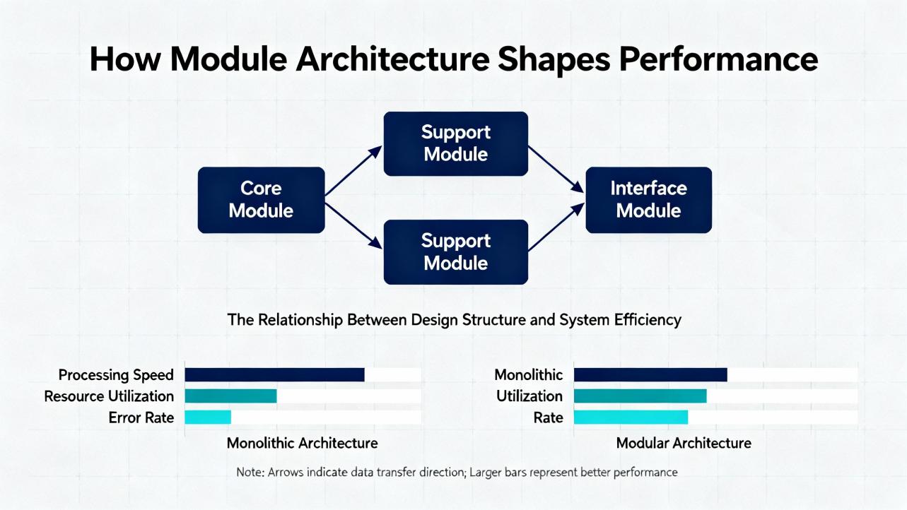
Most processŌĆægrade analog input modules use sigmaŌĆædelta ADCs. They trade raw conversion speed for high resolution, excellent lineŌĆæfrequency rejection, and digital filtering that knocks down 50/60 Hz and harmonics. If you need faster perŌĆæchannel updates across many channels, a multiplexed front end feeding a successiveŌĆæapproximation (SAR) ADC makes sense, but the onus shifts to your antiŌĆæalias filtering and wiring discipline. Established industrial design advice calls out this topology tradeŌĆæoff explicitly and suggests choosing sigmaŌĆædelta when the priority is maximum resolution and inherent mains rejection.
Isolation architecture is the backbone of noise immunity. Bus isolation uses a galvanic barrier between the controller backplane and field wiring to prevent commonŌĆæmode disturbances and fault energy from riding into the CPU. ChannelŌĆætoŌĆæchannel isolation goes further and isolates each input from the others, limiting crosstalk when channel grounds differ. Educational material on analog I/O makes the point clearly: independent isolation per channel protects accuracy when sensors sit on different ground potentials, while basic bus isolation often suffices for sensors sharing a clean reference.
Voltage inputs should be high impedance so they do not load the source. Industrial guidance commonly cites input impedances in the hundredŌĆækilohm range or higher for voltage inputs as desirable. For current loops, a 250 ╬® shunt across the input produces 1ŌĆō5 V from 4ŌĆō20 mA, which the ADC then measures with good resolution. Control engineering notes advise checking loop compliance so the transmitter can drive the total resistance including shunt, cable, and intrinsic safety barriers if present.
High channel density is often achieved by multiplexing many inputs into a shared ADC. In that case, the analog switch or multiplexer becomes part of your accuracy and noise story. Vendor application engineers recommend precision multiplexers designed for industrial ranges. When you multiplex differential signals to a single ADC in PLC applications, parts in the MUX36 family are cited as proven choices, with designs documented in reference designs including protection schemes. The same advice cautions that these devices do not specify poweredŌĆæoff isolation; if your input module can lose supply while field wiring stays live, you need powerŌĆæfault mitigation or external isolation to avoid leakage paths and latent errors.
Analog Devices has documented a highly integrated approach that many process engineers can use as a benchmark for both accuracy and noise immunity in a compact footprint. Their AD4111 combines a 24ŌĆæbit sigmaŌĆædelta ADC and precision passive front end capable of ┬▒10 V voltage inputs and 0ŌĆō20 mA current inputs while running from a single 5 V or 3.3 V supply. Critically, it keeps input impedance highŌĆöon the order of megaohmsŌĆöso voltage sources are not loaded. It tolerates significant overrange, producing valid conversions at ┬▒20 V and specifying absolute maximums of ┬▒50 V on voltage pins, which helps survive miswiring. For current loops, it covers measurements close to zero up to 24 mA, which makes realŌĆæworld ranging easier.
Noise immunity and diagnostics are built into the proposition. OpenŌĆæwire detection works even from a 5 V rail, decoupling openŌĆæwire faults from outŌĆæofŌĆærange readings and removing the need for highŌĆævoltage pullŌĆæups across the front end. That matters because it allows designs to drop legacy ┬▒15 V rails that complicate isolation and can raise emissions. The device integrates a reference and clock but allows external upgrades if your accuracy budget over temperature needs them. It also targets systemŌĆælevel total error so that in many cases perŌĆæchannel calibration can be eliminated; inputs are matched such that calibrating one input yields similar performance across others.
Perhaps most importantly for the ŌĆ£noisy plantŌĆØ question, Analog Devices built and characterized an EMCŌĆæproven input module around this approach. Their published board survived radiated and conducted RF challenges without permanent performance shifts and demonstrated immunity to ESD, EFT, and surge per the IEC 61000ŌĆæ4ŌĆæx family, with radiated emissions staying well below CISPR Class A. For engineers who have paid for a failed lab session, having a layout and filter example that passes is the shortest path to a firstŌĆætimeŌĆæright input design.
While integrated front ends are compelling, most of us buy PLC analog input modules from major vendors and plug them on a backplane. The same fundamentals apply. Strong candidates clearly state voltage and current ranges such as 0ŌĆō10 V, ┬▒10 V, and 4ŌĆō20 mA; resolution in the 12 to 24ŌĆæbit class; total accuracy or total error over temperature rather than only raw bit depth; and update rates per channel that hold up when the module is fully populated. Documentation that differentiates multiplexed perŌĆæchannel rates from aggregate ADC speed prevents misunderstandings during design.
Noise immunity shows up in the details. Look for galvanic isolation and, when needed, channelŌĆætoŌĆæchannel isolation for mixedŌĆæground installations. High input impedance for voltage, appropriate shunt and compliance for current, and selectable digital filtering options that explicitly target 50/60 Hz rejection are practical indicators. Leading references also call out antiŌĆæalias and lowŌĆæpass filtering, shield termination guidance, and digital averaging options. Diagnostics such as openŌĆæwire detection for current loops, overrange flags, and builtŌĆæin scaling and linearization for RTD or thermocouple inputs reduce commissioning time and field callouts. Where you plan to pass HART signals, make sure the input card supports HART passthrough. Finally, confirm environmental and EMC certifications and, when installations require it, hazardousŌĆæarea approvals.
The following table compares representative module approaches that are commonly evaluated for process control. Rather than listing every vendorŌĆÖs numbers, it highlights architecture and features tied directly to accuracy and noise immunity, citing where those features are documented.
| Option | Accuracy Features | Noise Immunity Features | Diagnostics and Protection | Isolation | Notable Pros | WatchŌĆæOuts and Notes |
|---|---|---|---|---|---|---|
| 24ŌĆæbit integrated front end (AD4111ŌĆæclass) | 24ŌĆæbit sigmaŌĆædelta conversion with high input impedance; valid ┬▒10 V and 0ŌĆō20 mA with precision dividers; targeted total error that can reduce perŌĆæchannel calibration | Inherent 50/60 Hz rejection from sigmaŌĆædelta filtering; EMCŌĆæproven reference design showing immunity to ESD/EFT/surge and low emissions | OpenŌĆæwire detection on 5 V; overrange tolerance to ┬▒20 V with absolute maximums to ┬▒50 V on voltage pins | Galvanic isolation implemented at board level in reference design with established digital isolators | Compact, singleŌĆærail supply; reduced BOM; proven EMC behavior | Requires following reference layout and filtering practices to hit EMC targets; verify accuracy budget over temperature for your range |
| Mainstream PLC AI card (sigmaŌĆædelta) | 12ŌĆō24ŌĆæbit datasheet resolution; vendorŌĆæstated total accuracy over temperature when well documented; perŌĆæchannel rates decrease with channel count on multiplexed cards | Configurable digital filtering and explicit 50/60 Hz rejection; shield termination guidance; highŌĆæimpedance voltage inputs and burden resistors sized for loops | OpenŌĆæwire detection for 4ŌĆō20 mA, outŌĆæofŌĆærange flags; builtŌĆæin linearization for RTD/TC on dedicated modules | Backplane to field isolation standard; channelŌĆætoŌĆæchannel isolation available on premium models | DropŌĆæin with PLC ecosystem; vendor diagnostics; robust configuration tools | Confirm perŌĆæchannel update at full load; verify total accuracy, not just bits; check HART passthrough if needed |
| VoltageŌĆæonly compact module (4ŌĆæch class) | Converts external voltages with vendorŌĆæspecified resolution and accuracy; fit for 0ŌĆō10 V panel signals | Acceptable on short, clean runs inside panels; limited inherent mains rejection compared to sigmaŌĆædelta with selective filtering | Basic input protection; diagnostics depend on model; review manual | Isolation varies by model; verify before deployment | Simple and costŌĆæconscious for local voltage signals | Not ideal for long, noisy cable runs; confirm input impedance and noise filtering |
| USB analog input module (bench/edge) | Oversampling boosts effective resolution; selectable bipolar and unipolar ranges including ┬▒10 V and 0ŌĆō20 mA | Galvanic USB isolation available; adequate for edge logging or nonŌĆæmissionŌĆæcritical tasks | CommandŌĆæline tools and APIs; simple scaling | USB isolation optional; not a PLC backplane device | Fast prototyping and data logging on PCs, singleŌĆæboard computers, or gateways | Not a replacement for PLC safety, EMC hardening, or plant certifications |
Table notes reference established sources. The integrated front end and its EMCŌĆætested board, the sigmaŌĆædelta line rejection behavior, the importance of high input impedance and burden sizing, and the role of openŌĆæwire diagnostics are all covered in vendor design notes and industrial trade guidance.
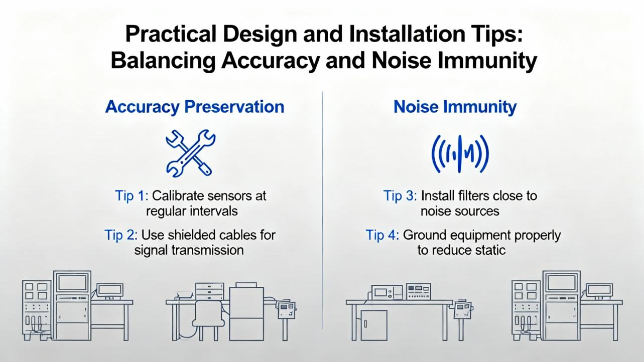
RealŌĆæworld performance starts with wiring. Use twistedŌĆæpair shielded cable for analog runs and terminate shields at one end to avoid ground loops unless your vendor specifies a different scheme. Physically separate highŌĆæpower conductors from lowŌĆælevel analog wiring and cross at right angles where necessary. Maintain singleŌĆæpoint grounding strategies around your I/O, paying attention to how isolation breaks return paths.
Choose differential inputs when sensors are distant or grounds differ. Educational references show that differential measurement cancels common ground noise, while singleŌĆæended wiring is more susceptible. Where you cannot avoid singleŌĆæended, keep runs short and inside cabinets where possible.
Match the moduleŌĆÖs range to the sensor so you use the full converter span. If your transmitter outputs 1ŌĆō5 V or 0ŌĆō5 V and your module only offers 0ŌĆō10 V, effective resolution is halved. If your module offers gain on the input path, use it judiciously to place your signal in the converterŌĆÖs sweet spot, but be mindful of headroom for expected overrange and transients.
Set sampling and filtering consistent with the process. As a default, aim for sample times five to ten times faster than the process time constant to keep the controller responsive without oversampling into noise. Take advantage of sigmaŌĆædelta digital filters and notches at 50/60 Hz when your plant power environment dominates interference. If you must multiplex many channels, remember that your perŌĆæchannel update rate falls as channel count rises. Avoid aliasing by adding antiŌĆæalias filters commensurate with the aggregated sampling scheme.
Design for faultŌĆætolerance. OpenŌĆæwire detection on 4ŌĆō20 mA is invaluable because 0 mA is a fault condition and needs to be flagged differently than a genuine 0% process value. Where you rely on analog multiplexers to increase channel density, remember the device behavior when power is lost. Some precision MUXes used in PLC applications do not guarantee poweredŌĆæoff highŌĆæimpedance. Add powerŌĆæfault handling or external isolation so field energy does not backŌĆædrive your module.
Finally, lean on vendorŌĆæproven EMC designs. If your plant has ever paid for a retest after failing an IEC 61000ŌĆæ4 burst or surge, you know the expense and delay. Reference designs that have been characterized for immunity and emissions dramatically reduce risk. Follow the exact component choices, ground splits, filter networks, and layout guidance where available.
If your priority is the best available accuracy and robust immunity in a compact module, consider a 24ŌĆæbit sigmaŌĆædelta front end with integrated precision passives, high input impedance, and builtŌĆæin openŌĆæwire diagnostics. The approach exemplified by the AD4111 is a strong benchmark. It runs from a single lowŌĆævoltage rail, tolerates realistic miswiring, and arrives with an EMCŌĆæproven board design that saves lab cycles. Use it when temperature or pressure loops must be tight, you want to avoid perŌĆæchannel calibrations, and your plant EMI history makes you cautious.
If your system already standardizes on a PLC family, select the analog input card within that ecosystem that specifies total error over temperature, configurable 50/60 Hz rejection, and isolation that matches your grounding scheme. For long runs across electrically busy areas, favor 4ŌĆō20 mA. When you need direct temperature inputs, use the vendorŌĆÖs RTD or thermocouple card with builtŌĆæin compensation and linearization; the wiring and scaling behavior are baked in and well supported.
If you need to increase channel density on a custom front end feeding a single highŌĆæquality ADC, multiplexers documented as suitable for industrial differential or singleŌĆæended inputs can deliver, provided you design in surge protection and handle powerŌĆæoff behavior. Review leakage and offŌĆæstate specifications because offŌĆæleakage contributes directly to error budgets at low signal levels.
If you are logging inside a panel or at the edge for analytics, compact voltageŌĆæonly or USB modules are perfectly adequate. They shine for short, clean runs where you control the wiring environment. They are not intended to replace PLCŌĆægrade EMC hardening or hazardousŌĆæarea requirements, so scope them appropriately.
Throughout, plan your HMI scaling and engineering units so that operators see meaningful values, not raw counts. Document calibration procedures and intervals. Confirm that controller firmware supports the diagnostics your module exposes so faults can be alarmed clearly rather than buried.

| Signal Type | Strengths for Noise Immunity | Accuracy Considerations | Typical Uses |
|---|---|---|---|
| 4ŌĆō20 mA current loop | Resists induced voltage noise over long runs; easy openŌĆæwire fault semantics at 0 mA | Input burden and loop compliance must match; shunt quality and temperature behavior add small error | PlantŌĆæwide transmitters for level, pressure, temperature, and flow |
| 0ŌĆō10 V or ┬▒10 V | Simple wiring and scaling; good inside panels with short runs | Sensitive to induced noise and ground offsets; input impedance must be high to avoid loading | Drives and positioners near the controller, panelŌĆælevel signals |
| Thermocouple | Wide temperature ranges; simple sensor construction | Millivolt levels require accurate coldŌĆæjunction compensation and linearization; routing discipline critical | HighŌĆætemperature measurements where RTDs cannot reach |
| RTD | High accuracy and stability over common ranges | Lead resistance must be managed with 3ŌĆæ or 4ŌĆæwire wiring; module linearization quality matters | Precision temperature loops across typical industrial ranges |
This table distills longŌĆæstanding guidance from industrial training and vendor documentation. The module and the signal type must work together; when they do, both accuracy and noise immunity benefit.
For process control, the ŌĆ£bestŌĆØ analog input module is not a single part number; it is the architecture that matches your signals, wiring reality, and control objectives. If you need uncompromising accuracy and resilience with minimal fuss, a modern 24ŌĆæbit sigmaŌĆædelta front end with high input impedance, openŌĆæwire detection, and a proven EMC design is hard to beat. If you are standardizing within a PLC platform, select cards by total accuracy over temperature, isolation style, and explicit 50/60 Hz rejection, then wire and ground them like you mean it. Use 4ŌĆō20 mA when runs are long or noisy. Sample fast enough to control, but not so fast you invite noise; filter with purpose, not habit. Finally, ask vendors for evidence: EMC results, total error budgets, and diagnostics that help your operators see faults, not just bad numbers.
Bit depth alone does not define loop accuracy. What matters is total error across your expected range and temperature, including gain and offset error and noise. A 16ŌĆæbit module can outperform a noisier 24ŌĆæbit device in practice. Start with the engineering range of your sensor, ensure your module uses the full span, and choose a design with strong line rejection and a wellŌĆædocumented total error over temperature. When in doubt, a 24ŌĆæbit sigmaŌĆædelta input stage with proper filtering and isolation gives you both resolution and noise immunity headroom.
Use 4ŌĆō20 mA for long or noisy runs and when ground differences are likely. The current loopŌĆÖs immunity to induced voltage makes it a safer choice across plant areas. Voltage is fine inside a cabinet or across short distances where wiring is controlled. Keep in mind that a 4ŌĆō20 mA loop encodes faults at 0 mA cleanly, and many PLC input cards will detect open wire and flag it, which simplifies diagnostics.
They improve robustness against ground offsets and interŌĆæchannel crosstalk when sensors reference different grounds. If all sensors share a local reference and wiring is short and clean, highŌĆæquality bus isolation may suffice. That said, for mixed grounds or when channels can experience different fault conditions, independent isolation is worth the added cost. Educational sources on analog I/O detail how isolation architecture influences interference and sampling integrity.
Sample five to ten times faster than your dominant process time constant as a starting point. This is consistent with standard process control practice and with data acquisition guidance that sampling at least ten times the highest frequency component maintains waveform fidelity. Then add filtering to suppress mains hum and broadband noise. Sampling faster without a plan inflates noise and processing without improving control.
Yes, with design care. Use industrialŌĆægrade analog multiplexers designed for your voltage and current ranges, add input protection per the vendorŌĆÖs reference designs, and size antiŌĆæalias filters for the reduced perŌĆæchannel sample rate. Be aware that some precision multiplexers do not guarantee highŌĆæimpedance behavior when unpowered; plan powerŌĆæfault handling so live field wiring cannot backŌĆædrive the module if a rail drops.
OpenŌĆæwire detection on current loops, explicit overrange and underrange flags, and builtŌĆæin linearization for RTD and thermocouple inputs shorten commissioning and speed troubleshooting. Modules that expose these diagnostics through the PLC data model make it easier to alarm faults and present useful messages on an HMI. Vendor documentation that includes lineŌĆæfrequency filter options and shield termination guidance reduces trialŌĆæandŌĆæerror during startup.
Analog Devices (Analog Dialogue and application notes on AD4111 and EMC); University of Michigan Chemical Engineering Encyclopedia on process control fundamentals; Texas Instruments E2E and TI Designs on industrial multiplexing devices and analog input module design needs; Control Design on analog input selection, resolution versus accuracy, isolation, and noise mitigation; RealPars on PLC analog inputs, 4ŌĆō20 mA and temperature inputs; Contec educational material on analog I/O, isolation, sampling, and quantization; Industrial Automation Co. overview of analog modules with PLC ecosystems; Maple Systems product overview for compact voltage input modules; LucidControl overview for USB analog input options.


Copyright Notice © 2026 mooreautomated.com All rights reserved,Moore Automated is not an authorized distributor or representative of the manufacturers featured on this website. Brand names and trademarks featured are the property of their respective owners.


Leave Your Comment