


MP 3009X
Get A Quote
Honeywell Experion PKS sites are increasingly full of smart sensors, valve islands, and stack lights hanging off IO-Link masters instead of traditional discrete cards. When everything is healthy, the C300 controller simply exposes clean process data and diagnostics. When something is wrong, you get IOLINK block soft failures, mysterious device timeouts, or IO-Link masters that flip in and out of error state while the process keeps running and operators lose trust in the automation.
This article walks through how IO-Link behaves in an Experion PKS environment, what the C300 IOLINK soft failures actually mean, and a practical, field-tested way to troubleshoot IO-Link problems without guesswork. The focus is on reliability and availability rather than lab-perfect theory, grounded in Honeywell documentation, IO-Link specifications, and vendor case studies.
IO-Link is an IEC 61131-9 standardized point-to-point serial link between an IO-Link master and a single device such as a sensor or actuator. According to the IO-Link Interface and System Specification, each master port can run as either a standard digital I/O (SIO) or a full IO-Link port. The physical layer is intentionally simple: a three-conductor unshielded cable with typical lengths up to about 65 ft per port, using common M5, M8, or M12 connectors and three defined communication speeds from a few kilobits per second up to a couple hundred kilobits per second.
On the controller side, the IO-Link master behaves like a remote I/O module. It aggregates cyclic process data and acyclic parameter and diagnostic data from devices and passes them to the control system. A technical article on commissioning IO-Link emphasizes that the real work for the PLC engineer is understanding how the master maps hundreds of bytes of process data and diagnostics into the controllerŌĆÖs I/O image, and then interpreting those bits and words correctly in control logic.
In an Experion PKS system, the C300 controllerŌĆÖs IOLINK function blocks provide the interface into this IO-Link world. The block supervises the IO-Link communication path and reports problems using soft failure indications rather than immediately treating every issue as a fatal module failure. Understanding those soft failures is the first step toward solving recurring IO-Link problems.
Before diving into errors, it helps to revisit what the C300 expects from IO-Link in normal operation.
The IO-Link technology description from vendors such as ifm clarifies that IO-Link cyclic data is a continuous, periodic exchange of digital measurement values and status between the master and devices. The content and format of this cyclic data are defined by each deviceŌĆÖs IO Device Description (IODD). Typically you have process data inputs carrying measurements and status bits, and process data outputs carrying commands or setpoints from the controller.
The IO-Link master and device also exchange acyclic data for parameters and diagnostics. The official IO-Link Interface Specification describes how the master uses index and subindex addressing to read and write parameters, and how it reports standardized diagnostic events such as line breaks, overcurrent, or undervoltage.
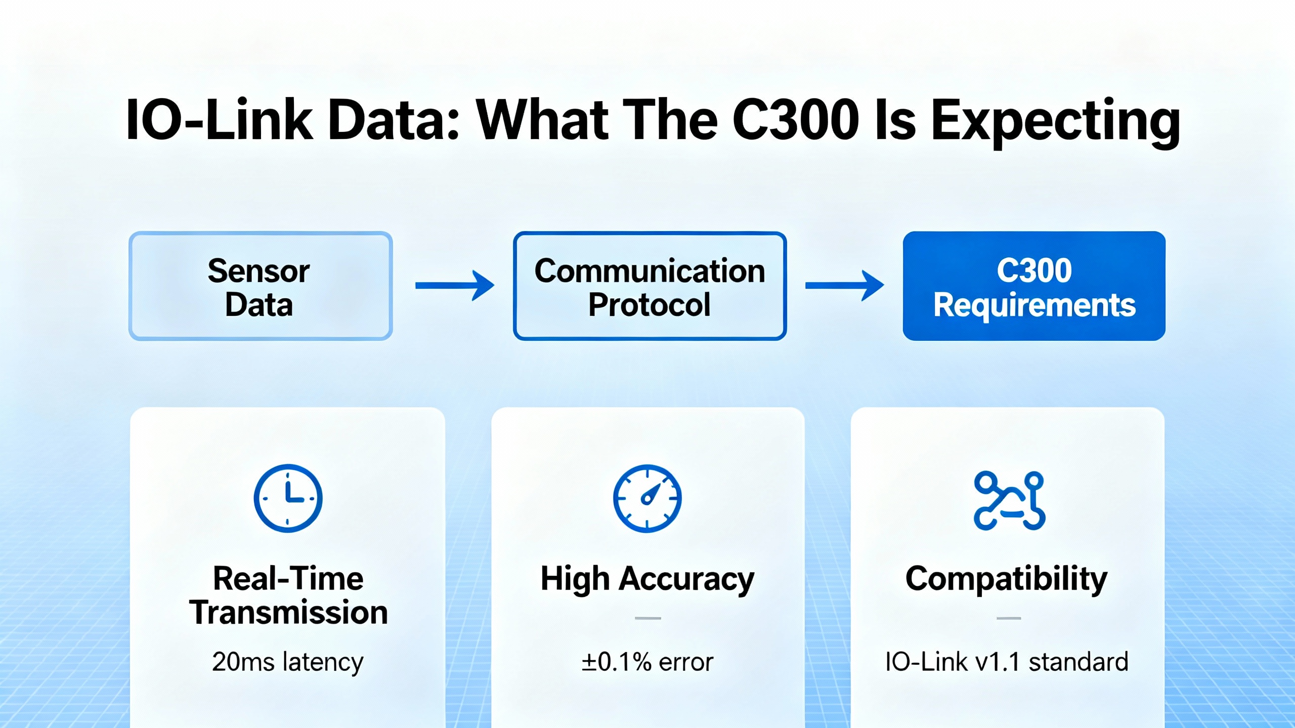
In Experion terms, the C300 expects:
Cyclic process data that arrives on time and with the correct size and layout as defined in the configuration files provided by the IO-Link master vendor, such as EDS, ESI, or GSD files described in the IO-Link system configuration guidance.
Parameters that are correctly provisioned so the device behaves as intended for trigger thresholds, logic, and output characteristics.
Diagnostics that are coherent so that the IOLINK blockŌĆÖs status and soft failures actually reflect real physical or configuration issues.
When any of these assumptions are broken, you will start to see IOLINK soft failures or erratic device behavior.
The Experion C300 Controller UserŌĆÖs Guide describes a set of IOLINK block soft failures. These are non-fatal indications that the IOLINK interface has detected a problem but the controller and the rest of the control strategy may still be operating. Each soft failure is documented with the condition and a recommended corrective action.
From the C300 manual excerpt, the following soft failures are particularly important for IO-Link engineers and technicians:
| Soft fail message | What it indicates in practice | Recommended action from Honeywell documentation |
|---|---|---|
| Device Index value is zero upon power up | A startup condition where the moduleŌĆÖs device index is not set correctly, showing up immediately after power is applied. Details in the excerpt are limited, but it flags a configuration or addressing issue at initialization. | Review the device index configuration for the module and verify it against the Experion hardware and control configuration manuals. Ensure that the module has a valid, nonzero device index before placing the controller in service. |
| Debug Flag Enabled | The C300 is running an engineering debug firmware image rather than the standard release image. This can change behavior and performance of blocks, including IOLINK. | If you are not intentionally running a special debug image under direction from Honeywell technical support, reload the controller with the standard C300 firmware that matches your Experion release. |
| Hardware Minimum Revision | The controller hardware passes power-on self-test and can technically run, but the hardware does not meet the minimum revision level required for the current system. | Replace the controller module with a unit that meets the required minimum hardware revision level for the Experion release in use. |
| Duplicate IOL Address | The system has detected a duplicate IO-Link address on the I/O network. In a C300, the IOLINK address is derived from the moduleŌĆÖs device index, with one partner expected to have an odd index and the other an even index. | Inspect the secondary IOLINK and I/O modules for their physical and configured addressing. Correct any duplicate or incorrect device index assignments so that partners follow the expected oddŌĆōeven scheme. |
These messages are soft failures, but they are operationally significant. If you ignore them, you can end up with symptoms like random device dropouts, IO-Link masters that appear to restart, or process data that flickers between valid and questionable values.
From a practical troubleshooting perspective, I treat any IOLINK soft failure as a structured hint about where in the end-to-end chain the problem lives: in controller firmware, hardware revision, device addressing, or startup configuration.
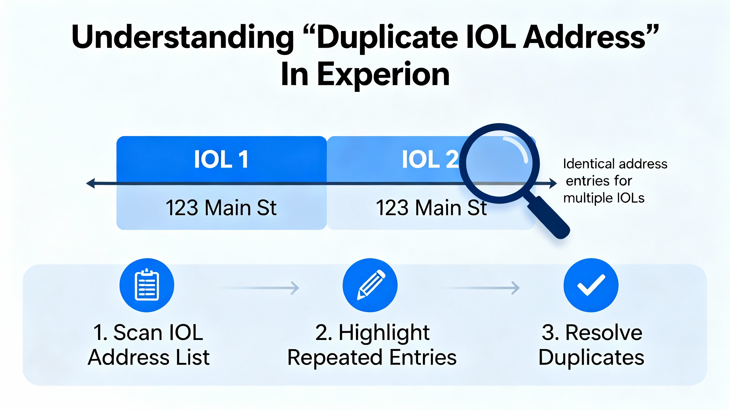
The Duplicate IOL Address soft fail is one of the most common IO-Link related messages you will see in an Experion C300 environment.
The C300 documentation states that the IO-Link address is derived from the moduleŌĆÖs device index, and that paired modules are expected to follow an odd and even pattern. The intention is that each partner on the IO-Link path has a unique derived address so that the controller can reliably map IO-Link communication to physical modules.
In the field, a Duplicate IOL Address usually points to one of three situations.
The first and most common situation is that a new I/O or IO-Link module has been added and its device index has been set to a value already used elsewhere, either because the engineering documentation was not updated or because the person on site followed a previous panelŌĆÖs convention without realizing this cabinet is different.
The second situation is that a pair of modules that should be configured as odd and even partners have both been assigned odd or both even device indices. Because the C300 expects one partner to be odd and the other even, this breaks the unique mapping of derived IO-Link addresses and triggers the soft fail.
The third situation is that a module has been replaced in a hurry, perhaps on a night shift, and the replacement moduleŌĆÖs physical address or configured device index was left at factory defaults instead of being aligned to the system design.
The remedy is always to trace the addressing chain rather than clearing the alarm and hoping it does not come back. In practical terms, that means reviewing how device index values are assigned in the configuration and, where applicable, checking the actual module address settings in the cabinet. Because the C300 derives the IO-Link address from the device index, every time you change indices you must verify that you have preserved the oddŌĆōeven partner relationship defined in the hardware manual.
After correcting addresses, perform a controlled restart of the affected I/O segment and verify on Experion that the Duplicate IOL Address soft failure clears and does not return during normal plant operation.
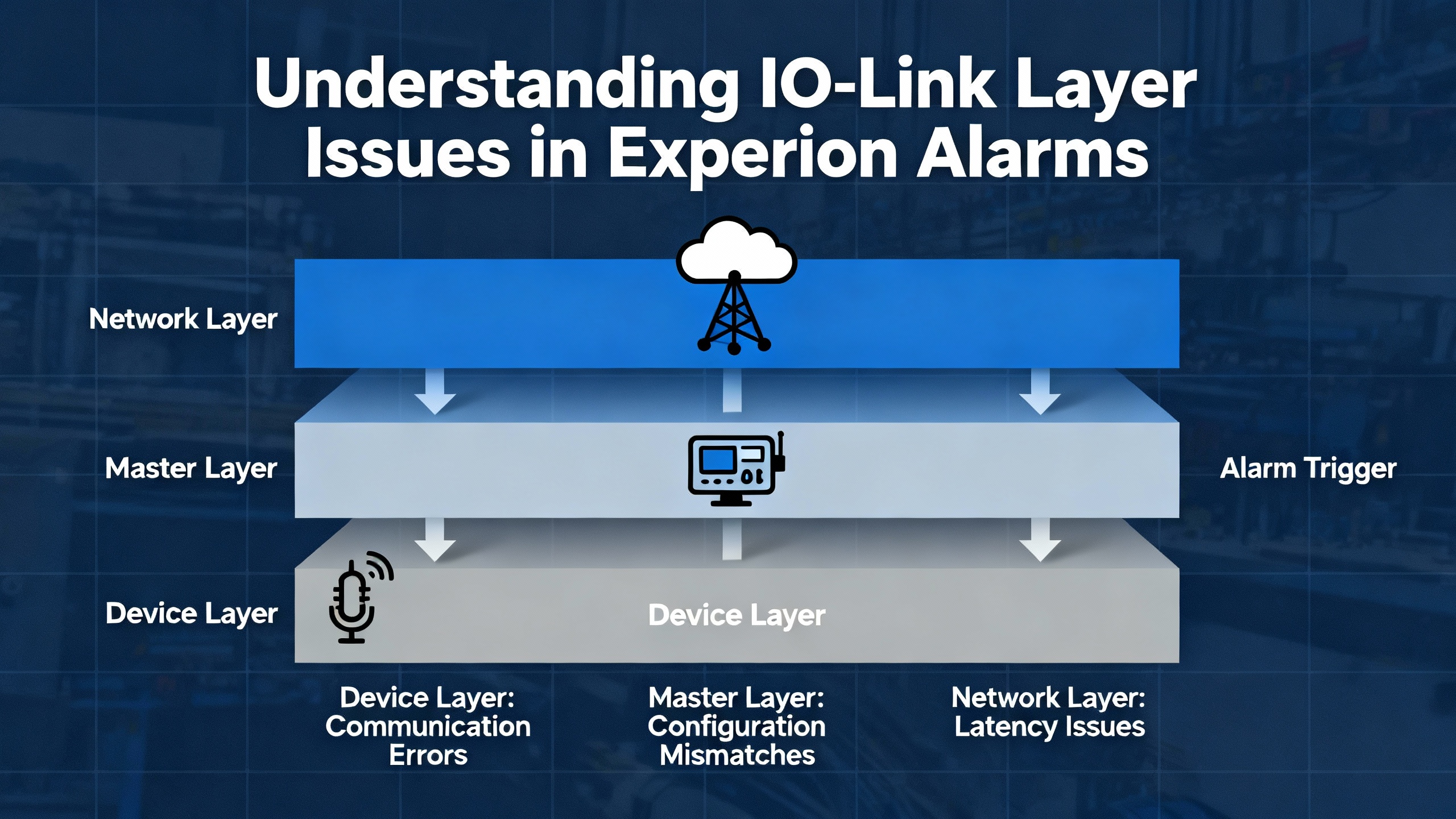
Not every IO-Link problem starts in the field wiring. Two of the soft failures from the Experion C300 documentation exist purely to catch controller-side issues that can cause intermittent or hard-to-explain IO-Link behavior: Debug Flag Enabled and Hardware Minimum Revision.
The Debug Flag Enabled soft failure tells you that the controller is running a special engineering debug firmware image rather than the standard production release. This is sometimes done under Honeywell technical support supervision to investigate a subtle system problem. In that mode, performance and behavior of blocks, including IOLINK, may differ from the formally released system, which can complicate IO-Link troubleshooting. The documentation is explicit: if you are not intentionally running a special image under Honeywell Service and Support Center direction, reload the C300 with the standard controller firmware for your Experion system release.
From a plant perspective, I encourage treating this as a housekeeping issue equivalent to having an unapproved control change in place. You should not invest time debugging IO-Link devices while the controller itself is running a nonstandard image unless that is an explicit part of a support case.
The Hardware Minimum Revision soft failure is a reminder that not all controller hardware is equal. The C300 manual notes that this condition means the hardware passes power-on self-test and is usable, but it does not meet the minimum hardware revision required for proper operation with the installed software. The recommended action is straightforward: replace the controller module with one that meets the required minimum revision.
In IO-Link heavy systems, marginal hardware can show up as communication timing issues, random soft failures, or intermittent restarts of communication-intensive blocks. If you see Hardware Minimum Revision in the same controller that also hosts IO-Link masters, treat hardware replacement as part of your IO-Link problem resolution plan rather than a separate IT project.
Finally, the Device Index value is zero upon power up soft failure references a startup condition where a moduleŌĆÖs device index has not been set correctly. While the provided excerpt does not include the full corrective text, it is clear that this is an addressing and configuration issue, not a wire or sensor problem. In practice, you should verify that each IO-Link related module has a valid device index configured according to the Experion C300 hardware manual and any site standards, especially after hardware replacement or cabinet rewiring.
Sometimes the C300 and I/O hardware are configured correctly, yet IO-Link devices still cycle through error states, or IO-Link masters report internal communication errors. In those cases, the root cause may lie inside the IO-Link masterŌĆÖs own handling of frames and buffers rather than in the DCS.
A useful case study appears in a B&R community discussion of their IO-Link card operating with LED strips. In that system, engineers traced a recurring error to an internal read buffer overflow inside the IO-Link card. The IO-Link library in the controller was behaving as designed; the card itself was entering an error state because acknowledgments from write cycles were not being pulled out of its internal buffer.
The IO-Link master was sending write commands to devices, and the card responded with echo frames that were meant to be read and acknowledged. Because the application did not explicitly read and acknowledge those echo frames, they accumulated in the cardŌĆÖs internal buffer until it overflowed. At that point, the card fell into an error state, and communication with connected IO-Link devices failed predictably after a fixed number of write cycles.
Engineers resolved this by implementing a small state machine around every IO-Link write. The pattern used states such as FLT_WRITE, FLT_WAIT_ECHO, and FLT_CHECK_ECHO. After issuing a write, the logic waited for the echo using a read function, captured the received frame into a buffer, and then called the write function again with a buffer length of zero and a specific sequence value to acknowledge the echo without sending new data. They also validated that the key header bytes and certain bits in the echo matched the sent frame. Only then did they accept the transaction and reset the command flag.
One interesting detail from that case is that the error appeared every 24 write cycles across all active channels, which worked out to 12 write cycles per channel given their pattern. That kind of predictability is a strong sign of an internal buffer limit or leak rather than noise or wiring.
The big lesson from this B&R example, which the vendor explicitly recommends, is that every IO-Link write in a multi-channel, high-frequency application should have a corresponding read and acknowledge step to clear the masterŌĆÖs internal buffers and to validate the echo. Ignoring echo handling is a good way to trigger obscure master-level errors that the DCS will only see as generic communication failures.
In a Honeywell Experion PKS project, you may not be writing raw state machines in the same way, but the principle stands. If you are integrating third-party IO-Link masters or device-level libraries under Experion, ensure that the integration layer honors the masterŌĆÖs requirements for reading and acknowledging frames. If you see repeatable IO-Link card resets or faults after a certain number of command cycles, consider buffer management and echo handling as a suspect, not just the wiring.
When an IO-Link problem hits a live plant, you rarely have the luxury of time. The process wants to keep running, and operators want alarms to clear. A structured flow makes it possible to resolve the problem safely without swapping hardware blindly.
Start at the Experion layer. When you see an IO-Link related alarm or a bad quality indication, open the diagnostic details for the affected C300 and look at the IOLINK block status. If a soft failure is indicated, note the exact soft fail message, such as Duplicate IOL Address or Debug Flag Enabled, and record the time it appeared. That message tells you whether to suspect controller firmware, hardware revision, device addressing, or startup configuration first.
Once you understand the soft fail, step down one level to the IO-Link master. Many Ethernet-based IO-Link masters described in the IO-Link system configuration article include a built-in web server accessible via IP address on the control network. From that web interface you can typically view port states, live I/O status, and device diagnostics. Some devices also allow adjustment of parameters online, which must be done cautiously on a running process. Compare the masterŌĆÖs view of each port and device with what the Experion IOLINK block believes is present. If the master shows a device missing, short circuit, or internal warning, address that physical or device-level issue before assuming a controller problem.
Next, verify addressing and device index alignment. For modules tied to the C300 IOLINK block, confirm, using engineering tools and the hardware documentation, how device indices are assigned and how those map to IO-Link addresses. Make sure that odd and even partner indices are correctly paired so that no two modules generate the same derived IO-Link address. If you have recently replaced modules or made cabinet changes, double-check that the new hardwareŌĆÖs indices match the configuration rather than factory defaults.
Then, focus on the device and its parameters. For IO-Link devices, parameterization is often richer and more complex than simple discrete inputs. The commissioning article on IO-Link stresses that many sensors and actuators require vendor-specific tools such as SICK SOPAS, Balluff Engineering Tool, or Banner configuration GUIs for deeper configuration than a PLC interface alone can provide. Confirm that the deviceŌĆÖs parameters, thresholds, timing, and logic functions match the intended design, and use the vendor tool to read back configuration when possible. A misconfigured threshold or output mode can look like intermittent communication if the device spends time in an unexpected internal state.
Finally, consider communication patterns. If your application sends frequent IO-Link write commands, especially to multicolor stack lights, LED strips, or valve manifolds, examine the logic that drives those writes. Use the B&R case as a pattern: ensure each write is followed by whatever read or acknowledgement pattern the master expects, and avoid sending writes from multiple tasks or controllers that might overlap and confuse the masterŌĆÖs internal state machine. If you can reproduce faults after a fixed number of commands, that is a strong hint to look at buffer handling and echo processing on the IO-Link master rather than the C300.
Throughout this process, resist the urge to delete historical data or clear archives to ŌĆ£free upŌĆØ a server when troubleshooting. Honeywell Experion PKS history archiving guidance points out that archives contain valuable process data and are stored uncompressed by default, which can consume disk space. The recommended approach is to enable Windows folder-level compression on archive folders or compress and offload older archives with standard tools, rather than deleting them. That historical data is often what you need to see whether an IO-Link problem has been present intermittently for months or only appeared after a recent change.
The best time to fix IO-Link errors is during design and commissioning rather than during a plant upset. Several practices from IO-Link specifications and vendor documentation make Experion PKS integrations more robust.
First, treat IO-Link configuration files as first-class artifacts in your control system. The IO-Link system specification and commissioning examples highlight the use of vendor-supplied configuration descriptions such as EDS for EtherNet/IP, ESI for EtherCAT, and GSD for PROFINET. These files define the size and structure of the process data and ensure that the C300 sees exactly what the IO-Link master is sending. Keep these files under version control, align them with tested firmware versions of the IO-Link master, and document any special interpretation of process bits or words.
Second, design IO-Link networks within spec rather than to the edge of the envelope. The IO-Link Interface Specification defines cable length limits, communication speeds, and port class constraints for a reason. In practice, that means keeping cable runs within the recommended lengths of roughly 65 ft per link, using appropriate IO-Link compliant power supplies, and choosing the correct port class for power-hungry actuators. Avoid doubling up loads beyond the intended capacity of an IO-Link port, even if it appears to work in the lab.
Third, select IO-Link masters and distributed I/O hardware that are appropriate for your environment. Bosch RexrothŌĆÖs S67E field I/O, for example, is an IO-Link based system designed for IP67 use in the field with screwable M12 connectors and up to eight IO-Link devices per master. For cabinet-level installations, IP20 rated modular I/O series are intended for DIN rail mounting. Matching device capability to the environment reduces nuisance faults from moisture, vibration, or temperature extremes, which the IO-Link master would otherwise report as intermittent device errors.
Fourth, think ahead about IO-Link Safety and IO-Link Wireless. The IO-Link Safety system description explains that safety-related IO-Link communication uses additional protocol measures like sequence counters and robust cyclic redundancy checks while still riding on the same three-wire physical layer. Properly implemented, IO-Link Safety can support safety functions up to SIL 3 or Performance Level e, but only when you use certified components and follow the manufacturerŌĆÖs safety manuals. Similarly, IO-Link Wireless is designed as a low-latency, highly reliable wireless extension of IO-Link for moving machinery where trailing cables and slip rings are problematic. It relies on time division mechanisms and tight supervision to guarantee determinism and extremely low packet error rates. Both technologies are powerful, but they introduce more configuration complexity, and in an Experion environment they should be planned and justified carefully rather than treated as simple drop-in replacements.
Finally, adopt a disciplined approach to IO-Link diagnostic use. IO-Link provides rich diagnostics about cable breaks, device identification, parameter mismatches, and more. Use that data deliberately by mapping key diagnostic bits into Experion points for alarm and maintenance displays rather than ignoring them. That way, when the IOLINK block reports a soft failure, your team already has supporting evidence from the IO-Link master and devices rather than facing a black box.
IO-Link itself is a device-level technology, but the path from Experion to IO-Link masters almost always crosses Ethernet. That path needs to be treated as part of your control system security posture.
A SecurityWeek article by Eduard Kovacs highlighted that vulnerabilities identified in Honeywell Experion PKS could enable manipulation of industrial processes. While the publicly visible summary does not provide all technical details, the core point is clear: weaknesses in control system software, configuration, or exposed interfaces can turn what should be a closed control loop into a reachable target.
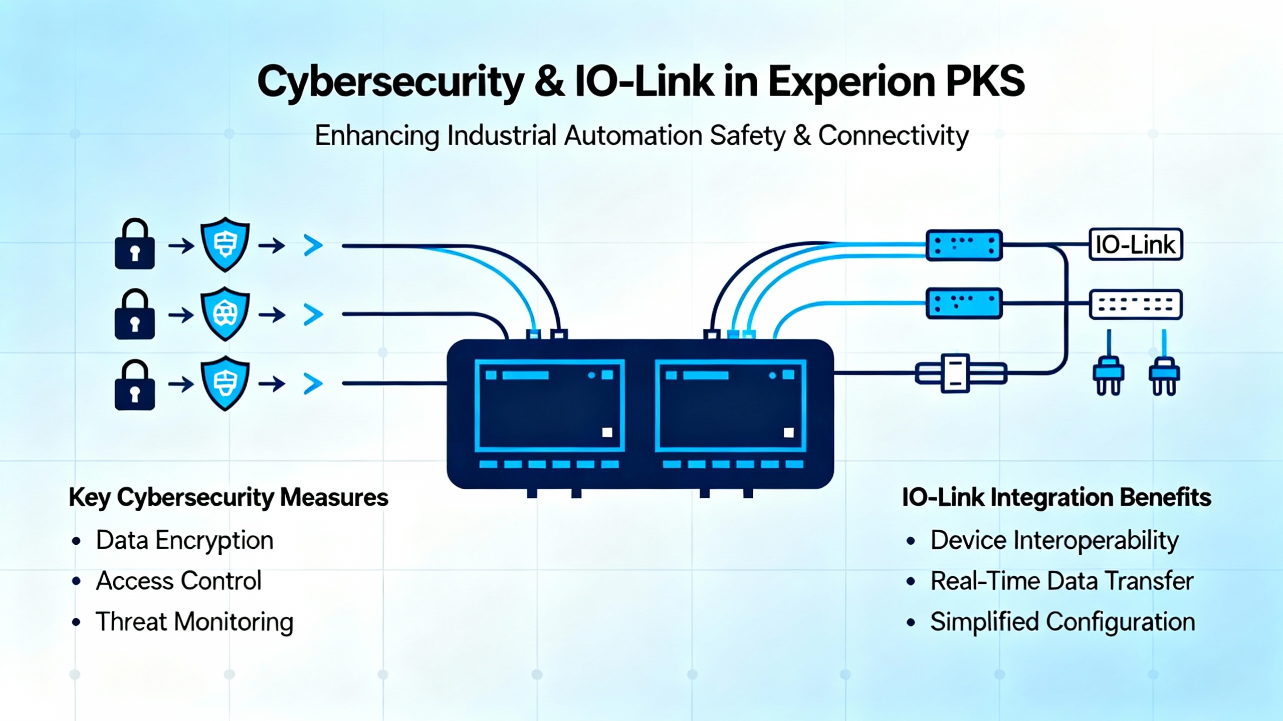
From an IO-Link standpoint, the main security risks are not in the IO-Link protocol itself, which is a point-to-point fieldbus, but in the masters and engineering tools used to configure them. Many IO-Link masters host web servers with diagnostic and configuration capabilities, sometimes including options to change device parameters online. If those web interfaces are reachable from corporate networks or the internet, or if credentials are weak, an attacker could alter device behavior or silently disable diagnostics.
In an Experion PKS project, practical security measures include keeping IO-Link masters inside well-segmented control networks, enforcing strong authentication on any web interfaces or configuration tools, and applying vendor patches and firmware updates promptly when security advisories are issued. Limit remote engineering access to Experion and IO-Link tooling to controlled maintenance windows, and monitor for unusual configuration changes, especially in IO-Link master parameters that affect process data or safety behavior.
OT and ICS security case studies, including those where companies have used centralized platforms to unify security across global operations, show that coordinated management of industrial assets pays off within a year when done correctly. IO-Link masters, device descriptions, and associated engineering stations should be part of that managed asset set rather than handled as ad hoc field devices.
IO-Link can transform an Experion PKS installation from a hardwired, opaque field into a smart, diagnosable infrastructure. The tradeoff is that you inherit a more complex communication stack, and problems can arise from controller firmware, hardware revision, device addressing, IO-Link master behavior, or device parameterization.
When I am on site with a plant that is fighting IO-Link issues on Experion, I focus on three principles. First, believe what the IOLINK soft failures are telling you and follow the Honeywell guidance on firmware, hardware, and addressing before you start swapping sensors. Second, treat IO-Link masters and devices with the same engineering rigor you apply to controllers by using proper configuration files, vendor tools, and buffer-safe communication patterns like the read-and-acknowledge approach proven in real IO-Link implementations. Third, fold IO-Link into your cybersecurity and lifecycle management practices, because a stable, secure infrastructure pays dividends every time you have to make a change or recover from a fault.
Handled that way, IO-Link errors in Honeywell Experion PKS become manageable engineering problems instead of recurring mysteries that erode operator confidence.


Copyright Notice © 2026 mooreautomated.com All rights reserved,Moore Automated is not an authorized distributor or representative of the manufacturers featured on this website. Brand names and trademarks featured are the property of their respective owners.


Leave Your Comment