


MP 3009X
Get A Quote
When a Rockwell drive trips, your line is down, and the counter on lost production starts immediately. IŌĆÖve been on enough factory floors to know that the difference between a twentyŌĆæminute hiccup and a multiŌĆæhour shutdown often comes down to how quickly and correctly you interpret the fault code, capture the conditions that caused it, and apply the right fix. This guide distills fieldŌĆætested practices for AllenŌĆæBradley PowerFlex drives and Rockwell servo platforms, references proven techniques from the broader motion control community, and adds practical advice from handsŌĆæon troubleshooting. The goal is simple: read it, walk back to your HMI or panel, and get the machine safely running again with confidence that the root cause was addressed.
PowerFlex platforms distinguish between alarms and faults, and the difference matters. Alarms warn about abnormal conditions without stopping the motor, while faults indicate unsafe or damaging conditions and force the drive to trip. Rockwell documentation for the PowerFlex 750ŌĆæSeries clarifies that faults are designed to protect the power stage, the motor, and your process. In practice, treat alarms as your early warning system and faults as the drive drawing a hard boundary for safety and equipment protection. The pattern I coach on site is to always record the exact text or code, any subcode if present, and the ŌĆ£faultedŌĆæatŌĆØ values like DC bus voltage, output current, output frequency, and temperature before cycling power or clearing anything. That snapshot is often your fastest path to the root cause.
Every good recovery begins with disciplined data capture. PowerFlex drives record a fault log and display the current condition on the keypad (HIM); configuration tools expose the same data in more detail. Before touching reset, write down the code and time, note process context like whether you were accelerating a heavy load or decelerating from high speed, and capture line conditions if possible. Service notes from experienced repair centers emphasize that resolving the code without fixing the cause is a recipe for recurring trips and longer future downtime. From the plant floor, the most reliable sequence is lockout and tagout, confirm the DC bus has discharged, document the event, then start with safe, reversible checks such as tightening terminals and reseating connectors.
Drive systems can store dangerous energy. Lockout and tagout, confirm the DC bus has fully discharged, and follow PPE requirements before any inspection or repair. This is not just a best practice; it underwrites every success story you will ever have in troubleshooting. Field guidance from industrial drive experts repeatedly notes that many ŌĆ£mysteryŌĆØ faults trace to simple, safeŌĆætoŌĆæcheck issues like loose terminations, overheated enclosures, or contaminated connectors. If burned smells or visible component damage are present, stop and escalate.

The PowerFlex 525 is a workhorse that reports a consistent set of faults with actionable meanings. Below is a concise table that maps what the code means to the most likely causes and what actually clears it in the field. The entries are summarized from repair specialists with direct PowerFlex experience and align with standard Rockwell practices.
| Code | Meaning | Likely Causes | Field Fixes |
|---|---|---|---|
| F003 | Power Loss | Incoming AC line lost or singleŌĆæphase condition | Monitor line stability, check fuses and feeders, reduce load if marginal power is unavoidable |
| F004 | Undervoltage | DC bus below minimum due to sags or interruptions | Stabilize incoming supply, investigate shared feeds with large loads that cause dips |
| F005 | Overvoltage | DC bus above limit from regeneration or surges | Lengthen deceleration ramps, add or validate a dynamic braking resistor, inspect supply for transients |
| F006 | Motor Stalled | Motor fails to reach or maintain commanded speed | Increase acceleration time, reduce mechanical load, inspect for binding, verify alignment |
| F007 | Motor Overload | Motor current above rating over time | Reduce load, confirm nameplate parameters and overload settings, check torque boost settings |
| F015 | Load Loss | Output torque fell below threshold too long | Inspect couplings and belts, correct unloaded or brokenŌĆælink conditions, tune loadŌĆæloss thresholds appropriately |
| F064 | Drive Overload | Drive rating exceeded | Extend accel time, reduce demand, evaluate if the drive is undersized for the application |
| F008 | Heatsink Overtemp | Power stage overheating | Clean fins and filters, confirm fan operation, improve airflow and enclosure ventilation |
| F009 | Control Module Overtemp | Electronics overheating | Improve airflow paths, clear obstructions, verify enclosure fans and ambient limits |
| F012 | Hardware Overcurrent | Instantaneous overcurrent threshold exceeded | Check motor and cable for shorts, reduce load spikes, verify programming that increases current demand |
| F013 | Ground Fault | Current detected to ground at the output | Megger test motor and cabling, correct insulation breakdown, reŌĆæterminate as required |
| F038ŌĆōF043 | Phase Faults | PhaseŌĆætoŌĆæphase or phaseŌĆætoŌĆæground faults | Inspect motor windings and cable insulation; replace damaged components if faults persist |
| F071/F072/F073/F081ŌĆōF083 | Network Loss | DSI or option or embedded Ethernet communications lost | Verify IP and comms settings, reseat modules, confirm cabling and switch health, configure loss actions appropriately |
| F002 | Auxiliary Input Trip | External trip input went active | Validate remote trip wiring and logic; confirm the trip is intentional and functioning as designed |
| F059 | Safety Open | Safety inputs inactive | Check safety terminals and jumpers when safety is not used; verify configuration |
| F091 | Encoder Loss | Feedback channel missing or unstable | Confirm wiring and power to the encoder, correct channel wiring, replace encoder if failed |
| F048 | Parameters Defaulted | Parameter store reset | Reload validated parameters from backup and retune where needed |
| F070 | Power Unit Failure | Power stage fault | Check ambient and cooling, cycle power, and replace the drive if the condition persists |
| F100/F101 | Parameter Storage Error | Storage or checksum error | Reset to defaults, reload knownŌĆægood parameters, and confirm stable operation |
| F105ŌĆōF109 | Module Mismatch | Control and power module mismatch or connection fault | Verify correct module pairing, reseat or replace as needed |
| F114 | Microprocessor Failure | Internal CPU fault | Cycle power and replace the control module if unresolved |
| F122 | I/O Board Failure | Control hardware fault | Replace the affected module or the drive if persistent |
| F125/F127 | Flash Update Required | Firmware corrupt or mismatched | Perform a correct firmware update per Rockwell procedure |
| F126 | NonŌĆæRecoverable Error | Critical internal error, autoŌĆæreset executed | Power cycle, replace the drive if the error recurs |
In practical terms, voltageŌĆærelated faults often correlate with production timing: undervoltage during line dips and shared feeders, overvoltage when decelerating highŌĆæinertia loads too aggressively, and drive or motor fault patterns that trace to damaged windings or old cables. If you see a recurring pattern, lengthen ramps, add a properly sized braking resistor or line reactor, and verify that parameter settings match the motor and the application. When parameter storage or module mismatch codes appear, lean on your backups. A knownŌĆægood parameter set and consistent firmware save hours.
Rockwell motion platforms and servo drives report FLTSxx conditions that point to specific subsystems. The following entries reflect a representative slice of common FLTS codes and their fieldŌĆæproven resolutions. Treat them as a quick reference to aim your first checks.
| Code | Meaning | Likely Causes | Field Fixes |
|---|---|---|---|
| FLTS10 | Inverter Overcurrent | Shorted motor cable, winding faults, or aggressive current demand | Inspect for shorts, verify motor winding integrity and cable gauge, reduce acceleration demand |
| FLTS11 | Inverter Overtemperature | Power stage beyond thermal limit | Reduce speed or duty cycle, lower ambient, improve airflow and heatsinking |
| FLTS13 | Inverter Thermal Overload | Transistor thermal model exceeded capacity | Reduce duty cycle and revisit motion profile timing |
| FLTS16 | Ground Current | Excessive current to ground | Check power wiring and insulation, replace the motor if the fault persists |
| FLTS23 | AC Phase Loss | Input phase missing while enabled | Confirm incoming AC voltage on all phases and remediate upstream issues |
| FLTS25 | PreŌĆæCharge Failure | DC bus did not reach target during precharge | Verify line power and input wiring, replace the drive if the condition repeats |
| FLTS29 | Bus Overload (Shunt) | Dynamic brake thermal model exceeded | Reduce duty cycle, add an external shunt, or add bus capacitance per design rules |
| FLTS34 | Bus Undervoltage (User) | DC bus below user limit | Stabilize incoming AC, address sags or droops, consider a UPS, or adjust the user threshold responsibly |
| FLTS35 | Bus Overvoltage | DC bus above factory limit | Extend deceleration time, validate braking resistor and chopper, and replace the drive if the shunt is open |
| FLTS37 | Bus Power Loss | DC bus below threshold beyond allowed time | Confirm line integrity and install holdŌĆæup measures if needed |
| FLTS41 | Feedback Signal Noise | Illegal A/B transitions or excessive noise | Inspect feedback cabling and shielding, secure connectors and grounds, reduce shock and vibration, replace motor if required |
| FLTS45 | Feedback Communication Fault | Consecutive missed or corrupted packets | Verify feedback device power, cable integrity, shielding, and motor frame ground |
| FLTS50/51 | Hardware Overtravel ┬▒ | Axis exceeded limit switch | Check limit wiring, review motion profiles, and validate axis configuration |
The pattern within FLTS codes is instructive. If the code references the DC bus, focus upstream on the supply and braking path. If it references feedback, suspect cables, violent motion, or grounding before blaming the drive. If it references overtravel, the axis is doing what it was told and your fix lies in wiring and motion limits, not electronics.
Drives are often innocent bystanders to network or safetyŌĆæcircuit issues. Communication loss codes, whether on DSI or EtherNet/IP, respond remarkably well to the basics: reseat option cards, validate IP settings, replace questionable patch cords, and check the health of the network infrastructure. Safety open conditions appear when safety inputs are not satisfied; treat this as a wiring or configuration matter and verify jumpers only when the safety function is intentionally bypassed per your risk assessment. Encoder and feedback loss errors often trace to pinched cable jackets, failing connectors, or power to the feedback device dipping under load. Prioritize careful inspection and remember that a shield is only as good as the ground you give it.
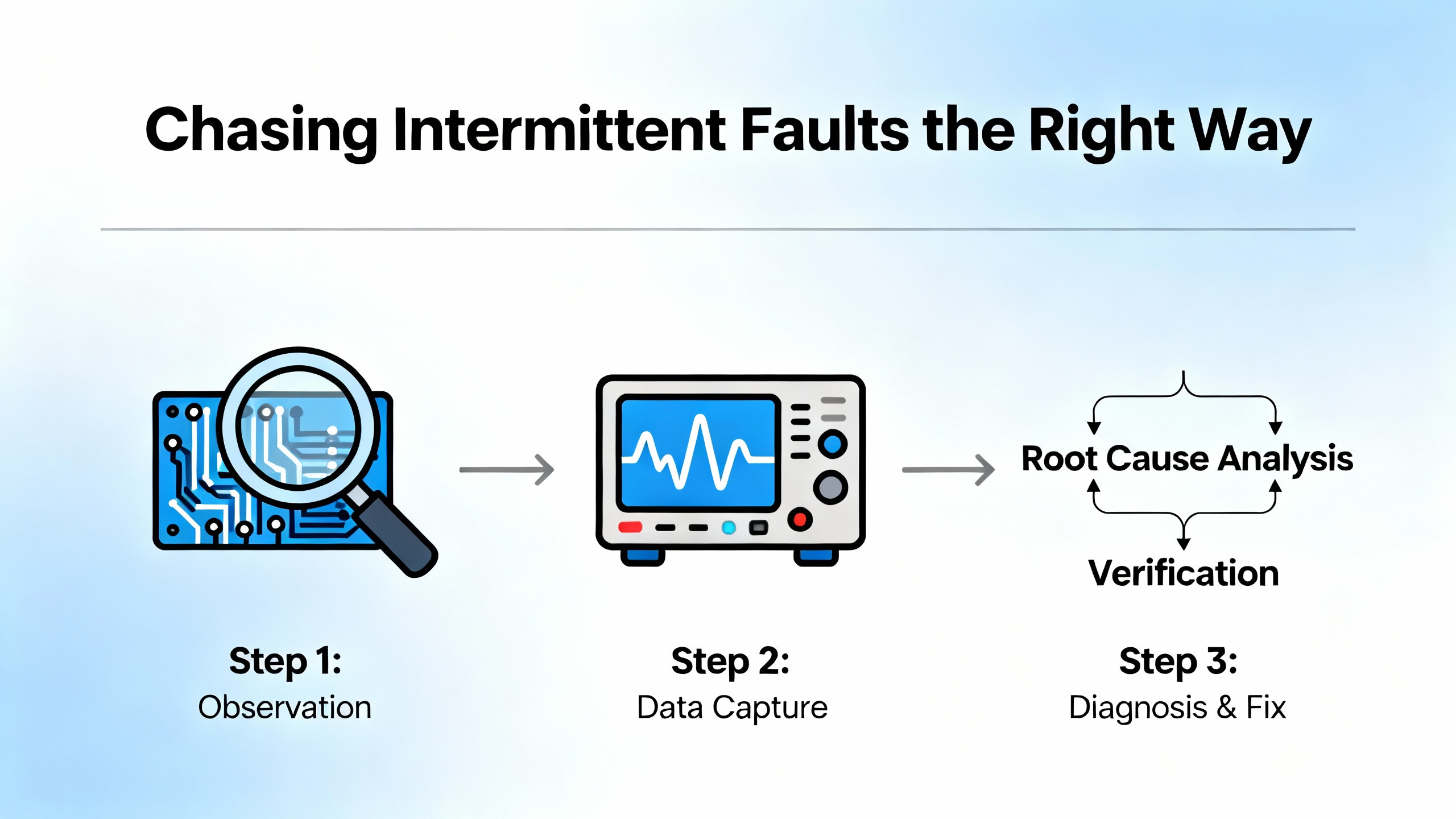
Intermittent faults are the ones that make people say they hate drives, when the real culprit is a messy process or a small wiring defect. Motion control practitioners emphasize a disciplined approach. Start with inductive reasoning to list plausible causes of the specific code, then apply deductive tests to eliminate them. Document exactly what happened and when, ask what changed recently in software, hardware, or process, and replicate the fault under controlled conditions.
TriggerŌĆæbased data capture is your best ally. Most modern drives or their tools include a scope function that can be set to trigger on the next occurrence of a given fault. Capturing a short window of key channels just before and after the eventŌĆösuch as supply voltage, output current, and speedŌĆöanswers the critical question of cause and effect. Practitioners describe solving undervoltage faults by correlating line dips to high acceleration, and a particularly memorable case of repeated resets that traced to an uninitialized memory variable that reliably caused illegalŌĆæaddress resets after a unitŌĆæspecific time interval. In mechanical domains, a recurring encoder fault that initially reset itself and later hardened into a permanent failure was traced to axial loading from a tight motorŌĆæencoder stackup. The redesign that relieved axial load eliminated the issue completely. These are not drive problems in the narrow sense; they are system problems you can only see by stepping back and letting data, not guesswork, point the way.
Stress testing is the closer for many heisenbugs. Vary line power slightly, induce mechanical and thermal stress thoughtfully with a heat gun or freeze spray where safe, and examine solder joints and connectors under bright light for the telltale wink of a cold joint. If noise or RF susceptibility is suspected, injecting controlled RF energy near boards during a safe benchŌĆætest can quickly clear or confirm your hypothesis. The theme is method over magic: make it fail faster, capture the evidence, and fix the cause you can prove.
Drives fault to protect themselves, and controllers fault for similar reasons. In Logix platforms, a ProgramŌĆælevel fault routine can capture fault data, set a flag for your HMI, and even attempt a conditional clear so you can execute an orderly shutdown. Practitioners commonly use a GSV to store structured fault information in a UDT, set a fault flag that normal logic can surface to operations, and then clear with an SSV when conditions permit. The important nuance is scope. A Program fault routine only runs when the processor is scanning that Program, and it will not execute for nonŌĆælogic faults like a required I/O module dropping. That is why projects that span multiple Programs often include a Controller Fault Handler. The CFH is the last resort that executes on systemŌĆælevel issues and I/O faults, where you can apply the same three steps: flag, capture, and carefully consider clearing.
The philosophy that separates safe plants from risky ones is this: use routines to orchestrate safe, deterministic states, not to hide problems. If you can clear a nuisance comms fault and keep running while you trend the network, do it with intention. If a powerŌĆæstage error appears or a module reports a hardware failure, favor a controlled stop and human eyes on the equipment before attempting restarts. Rockwell error catalogs for I/O modules and messaging also reinforce that ŌĆ£extended error codesŌĆØ carry the detail; make inspection of the extended status part of your normal response.
Preventing trips is not glamorous work. It is panel housekeeping, environment control, and parameter discipline. Keep heatsinks and filters clean and verify fans are moving air; dust and heat are silent killers that show up as thermal faults long before they become obvious. Protect power quality with surge protection, validate grounds and shielding, and route power and control conductors appropriately. Match drive parameters to the motor nameplate, select realistic acceleration and deceleration times for the inertia at hand, and configure current and torque limits that protect the hardware while meeting process needs.
For current and ground faults, perform insulation testing to catch moisture ingress and cable damage early. For brakingŌĆærelated issues, pair deceleration needs to the correct dynamic braking resistor and chopper hardware. For communication and encoder problems, reseat or replace suspect connectors and confirm that the feedback device power is solid at the device under load. Maintain current firmware where recommended, keep parameter backups for quick recovery, and log configuration changes alongside fault histories so future you can skip the detective work.

Some drive faults are invitations to repair; others are warnings to replace now. Repeated power unit failures, microprocessor faults, and nonŌĆærecoverable errors point to damaged hardware where chasing gremlins wastes time and money. In those cases, replacing the drive is usually the fastest path back to production. Conversely, when a control board is stable but the system is tripping on comms or thermal issues, a measured repair that cleans, cools, and corrects wiring pays off. Experienced repair centers report that returning to a knownŌĆægood parameter set, cleaning airflow paths, and reseating modules resolve a surprising share of fault patterns without parts replacement. Abuse that wisdom judiciously: when the power section says it is hurt, listen.
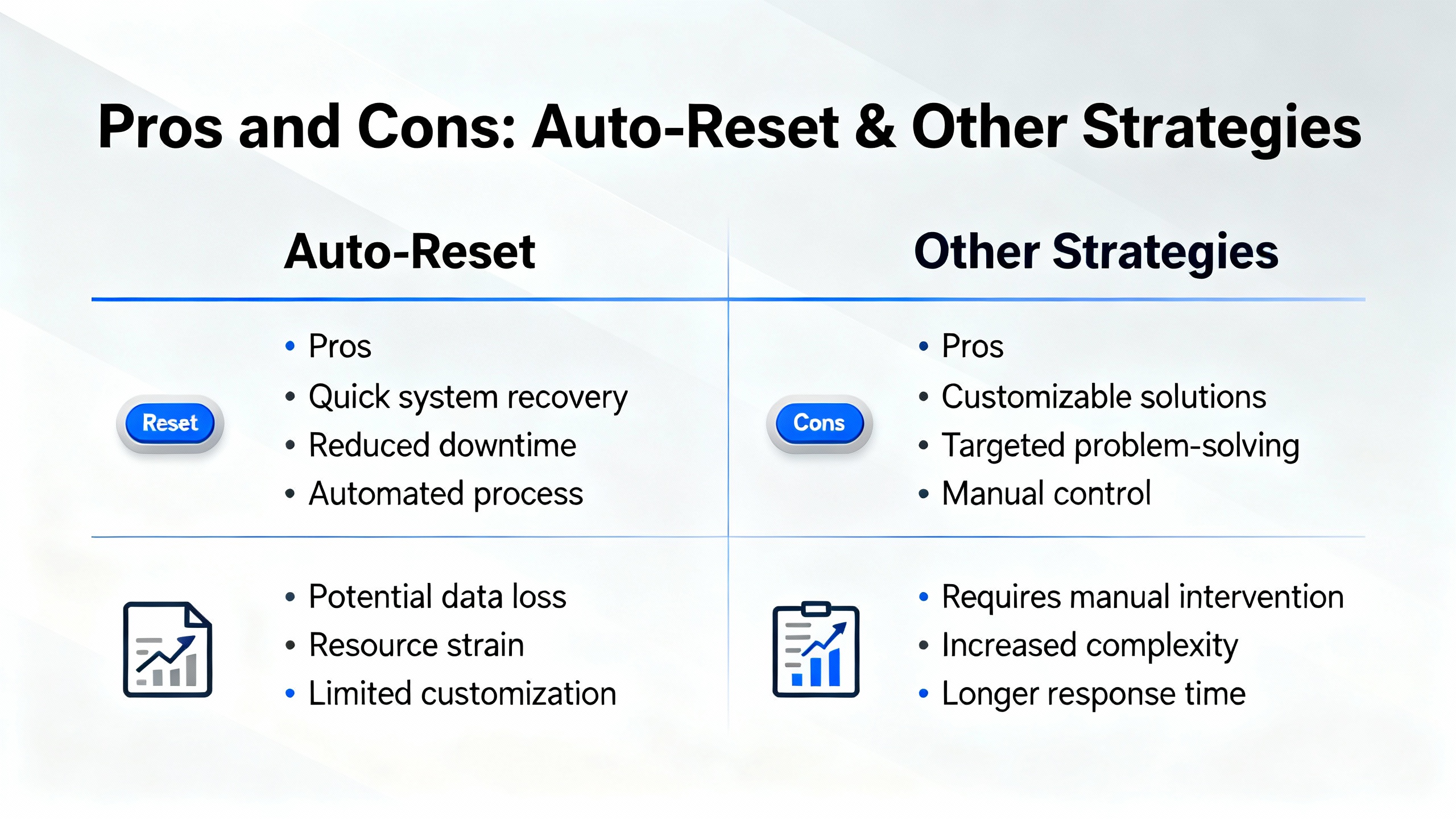
Automatic fault resets can reduce nuisance downtime in benign conditions like brief network hiccups or line sags. The advantage is speed, particularly when you pair autoŌĆæreset with robust logging so you do not miss the initial symptom. The downside is masking real problems until they become worse and harder to diagnose. Manual resets force an operator to acknowledge the condition and can be paired with a controller routine that sets interlocks for a controlled restart. The most reliable pattern combines conditional clearing with limits on retries, and a clear rule that any powerŌĆæstage or safety fault calls for human intervention. That balance keeps nuisance events from dominating your shift without training people to ignore persistent, important signals.
The best first step is always documentation. Record the code and the conditions, then move to the checks most correlated to your fault category. For overvoltages, lengthen decel and verify braking; for undervoltages, stabilize the supply and check shared feeders; for overcurrents and stalls, lighten the load and lengthen accelerations; for ground faults, megger the motor and cable; for thermal issues, clean and cool; for network and encoder problems, verify wiring and power and reseat everything that plugs into something. When parameters default or storage faults appear, restore from backup and verify firmware integrity. When hardware failures report themselves repeatedly, stop chasing and plan the replacement.
What is the safest way to clear a drive fault and restart production without hiding risk? The safest approach is to capture the code and context, perform lockout and tagout, correct the root cause you can prove, then clear the fault and use a controlled start sequence. If you use autoŌĆæreset for nuisance events, limit retries and log each event so patterns are visible.
How do I know if a ground fault is in the motor or the cable? An insulation resistance test with a megohmmeter separates the two quickly. Disconnect at the motor and at the drive, test segments independently, and look for any phaseŌĆætoŌĆæground leakage. Replace or reŌĆæterminate the segment that fails the test.
Why does my drive overvoltage only on fast stops with heavy loads? Regenerative deceleration pushes energy back into the DC bus. If the bus cannot absorb it, the drive will trip on overvoltage. The fieldŌĆæproven fixes are to lengthen deceleration times or to add and validate a properly sized dynamic braking resistor and chopper.
The patterns and fixes in this guide align with Rockwell Automation product documentation and draw on frontline briefs from Industrial Automation Co., practitioner guidance shared on PLCtalk, and motion control troubleshooting insights published by Automate. VendorŌĆæagnostic maintenance and triage practices summarized by Emotron and Zero Instrument further reinforce the basics: capture the code, correct the cause, and prevent replays through disciplined configuration and housekeeping.
I write this as someone who has been the person with a meter in one hand and a radio in the other on a noisy plant floor. Drives are honest. When they tell you what hurts, listen, verify, and fix the real problem. Do that consistently and faults turn from fire drills into guardrails that keep your operation running safely and predictably.


Copyright Notice © 2026 mooreautomated.com All rights reserved,Moore Automated is not an authorized distributor or representative of the manufacturers featured on this website. Brand names and trademarks featured are the property of their respective owners.


Leave Your Comment