


MP 3009X
Get A Quote
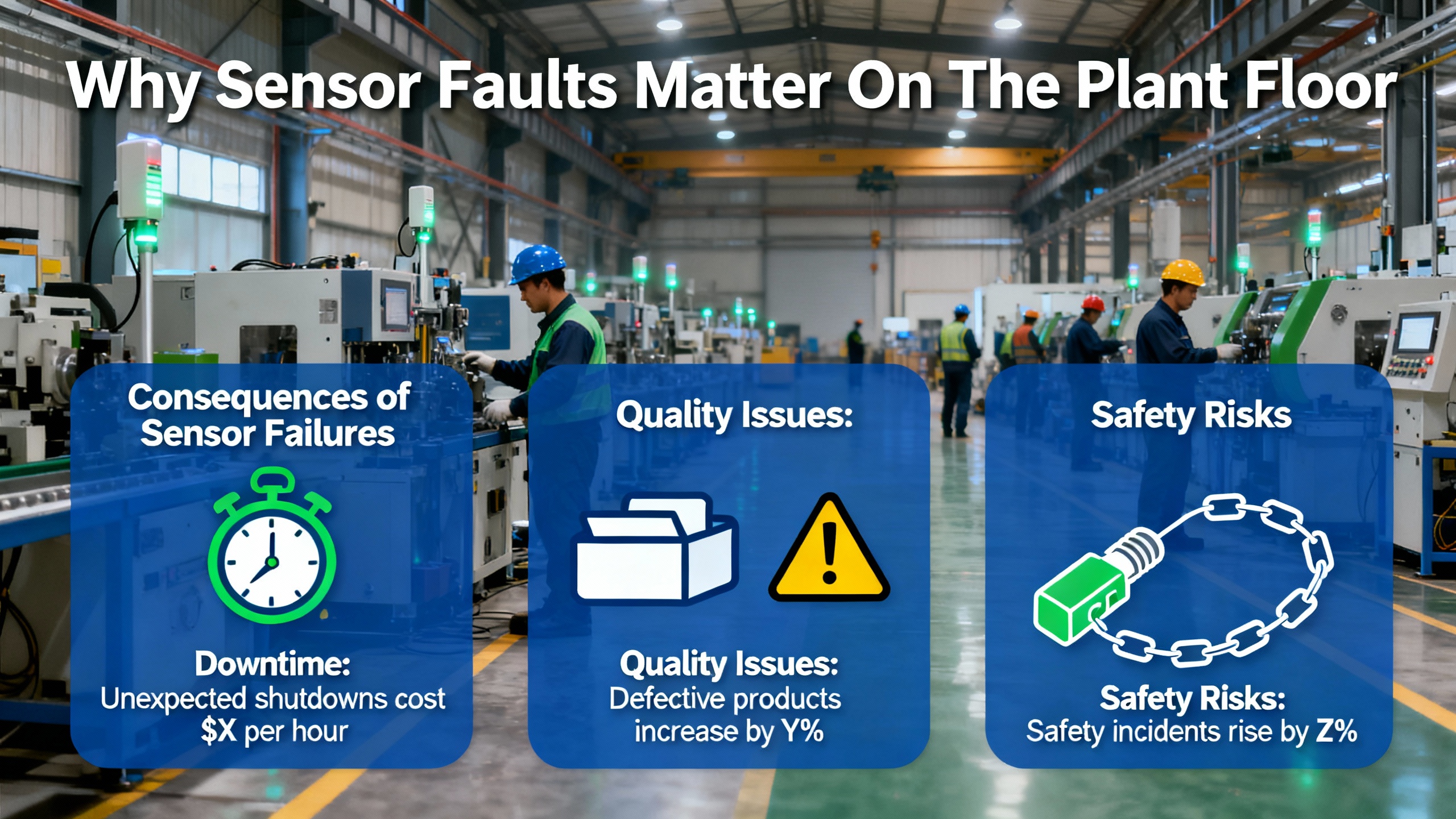
In a modern plant, Pepperl+Fuchs sensors sit right on the front line. Whether they are detecting a part on a conveyor, confirming a valve position, or feeding an analog process value into a PLC, they are the eyes and ears of your automation system. When a sensor lies, drifts, or dies, the PLC logic and HMI screens still look perfectly rational, but the decisions are wrong. That is how you end up with overŌĆæfills, dry runs, jammed conveyors, hidden safety risks, and a production manager asking why a simple proximity switch just cost thousands of dollars in downtime.
Instrumentation specialists often describe the field devices as the ŌĆ£nervous systemŌĆØ of a plant. A Glomacs article on instrumentation failures emphasizes that inaccurate or failed sensors do not just hurt efficiency; they can make a process unsafe and push you out of regulatory compliance. In my own work commissioning and troubleshooting PLC lines, most nasty production incidents had a simple root cause in a single sensor circuit that everyone ŌĆ£knew was fine.ŌĆØ
The good news is that sensor faults are rarely mysterious. They follow patterns. If you bring a disciplined troubleshooting method, understand the usual failure modes, and combine that with the builtŌĆæin diagnostics of your PLC and conditionŌĆæmonitoring tools, you can usually get from symptom to root cause quickly and safely.
Articles on field instruments and sensors from industrial sources like Jiwei Automations, Glomacs, Metrol, and WF Sensors all converge on the same families of problems. Whether the label on the housing says Pepperl+Fuchs or any other reputable brand, the underlying physics and failure mechanisms are the same.
Common failure patterns include distorted or missing signals. JiweiŌĆÖs review of field instrument faults highlights cases where the sensor output is wrong or absent due to damaged sensing elements, cable problems, or transmitter electronics. In practice that shows up as a discrete input that never turns on, an analog value stuck at a fixed number, or a reading that jumps randomly.
Inaccurate readings are another major category. Over time, process sensors drift away from their original calibration. Environmental factors, such as temperature swings, humidity, vibration, and contamination, can push readings off by just enough to ruin tight control loops. Glomacs points out that drift and calibration error in pressure, flow, and temperature sensors are a leading cause of inefficient and unsafe operation.
You also see nuisance fault alarms rather than clear hard failures. Jiwei notes that bad configuration and unstable power can trigger constant alarms even when the process is fine. Poorly set thresholds, EMI, or a noisy signal can convince the control system that a sensor is failing when the problem really lives elsewhere.
Mechanical abuse is another frequent culprit. MetrolŌĆÖs failure analysis of position sensors shows that violent mechanical handling, angled impacts on straightŌĆæacting switches, and lowŌĆærigidity mounting jigs can all damage internal contacts and destroy repeatability. In the field I regularly see sensors mounted on thin brackets that flex every cycle; the jig moves more than the sensor repeatability spec, so the ŌĆ£faultŌĆØ is structural, not electronic.
Cable damage rounds out the short list. Cables bent tighter than their design radius, crushed under covers, or eaten by chips and coolant will eventually crack the conductors or insulation. Metrol notes that this leads to core breakage and coolant ingress, while WF Sensors emphasizes that poor wiring, loose connectors, and insulation breakdown show up as intermittent faults, zero drift, and outright failures.
If you add up those categories, you get a simple reality: most Pepperl+Fuchs sensor problems are not exotic. They are power, wiring, mounting, environment, or configuration issues that repeat across assets and across sites.
Before talking about fault detection and clever diagnostics, it is worth repeating the most important point from the DigiKey TechForum guide on troubleshooting industrial control equipment: you are responsible for your own safety.
Industrial panels and machines can expose you to lethal voltages, crushing forces, pressurized fluids, and chemicals. The DigiKey article walks through hazards that range from electric shock and arc flash to hydraulic injection injuries. It insists on Lock Out Tag Out, compliance with OSHA and local regulations, appropriate PPE, removal of conductive jewelry, and working with a partner when possible.
In practice, proper sensor troubleshooting starts with safe isolation and a cool head. Take the time to understand the machineŌĆÖs operating sequence and hazards before you ever put a meter on a terminal block. The same guide also stresses that the best troubleshooters know the equipment cycles intimately. If you do not know what ŌĆ£goodŌĆØ looks like, you will misinterpret what you see on LEDs and HMIs, and you will be tempted to poke randomly rather than work a structured procedure.
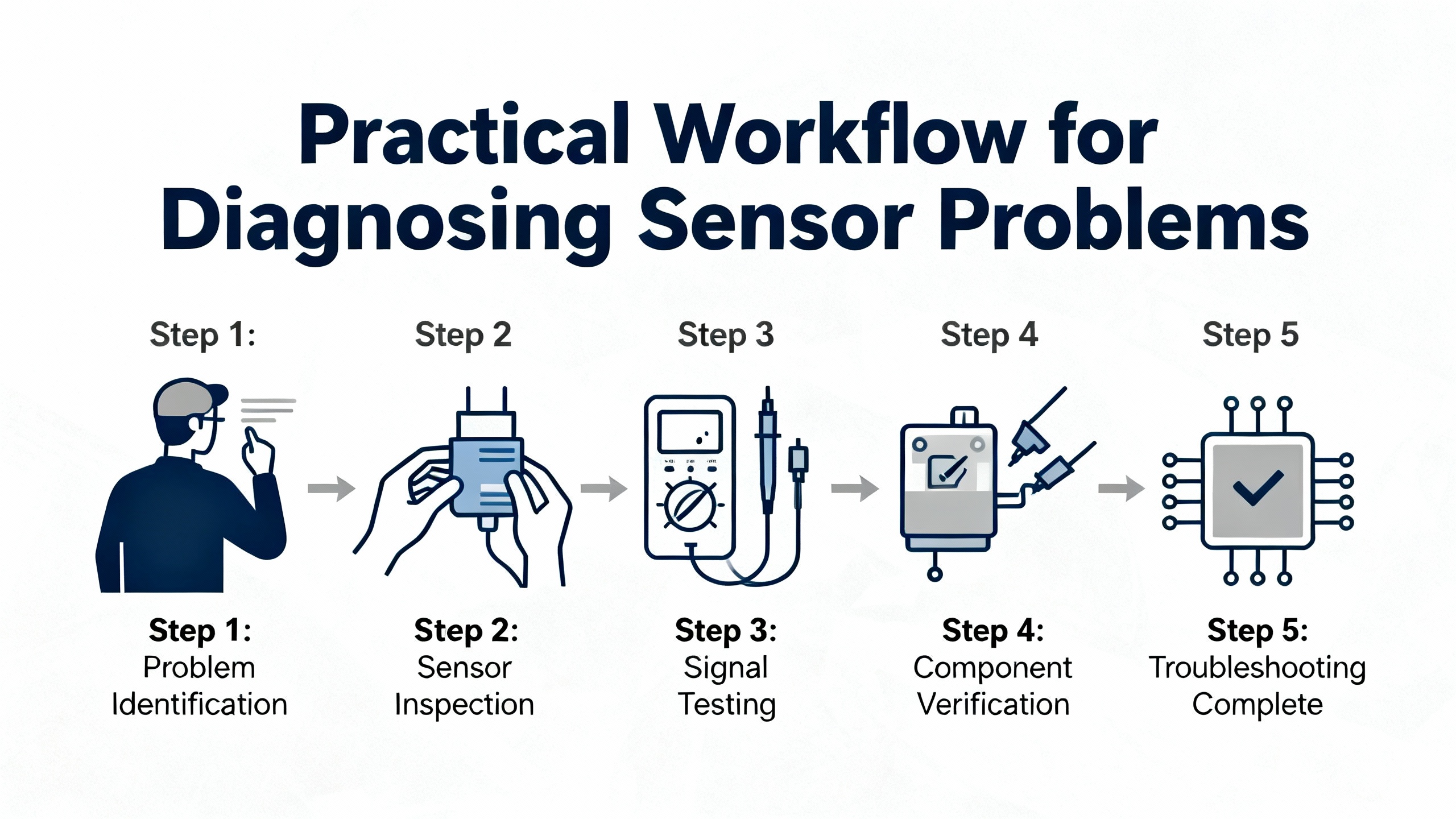
A proven approach is to adapt the Navy 6ŌĆæstep troubleshooting procedure, as summarized in the DigiKey TechForum article, specifically to sensors.
Start by recognizing and describing the symptom clearly. Is the sensor apparently dead, intermittently dropping out, reading too high or too low, or spamming alarms? Capture what the operators see, when it happens in the cycle, and what changed recently in the machine or process.
Then elaborate the symptom rather than chasing the first clue. Run the machine, or simulate the cycle, up to the point of failure if it is safe to do so. Confirm whether one sensor or several show abnormal behavior. Use the HMI, PLC diagnostics, and any builtŌĆæin alarm logs to refine the picture. Jiwei and Glomacs both recommend combining operator observations with trend data, because some faults are temperatureŌĆædependent or intermittent.
Next, list the plausible blocks that could produce the observed behavior. For a Pepperl+Fuchs discrete sensor feeding a PLC input, the trouble could be in the sensor itself, the cable, the junction box, the 24 VDC power supply, the PLC input module, or even a mechanical misalignment between target and sensing face. WF Sensors recommends verifying the physical, electrical, and mechanical environment at this stage, rather than cutting straight to the oscilloscope.
After that, localize the fault to one block and then to one component using tests. The DigiKey guide describes a ŌĆ£divide and conquerŌĆØ or halfŌĆæstep voltage check method, especially for 24 VDC control circuits. Measure at the supply, measure at the far end, and progressively narrow the segment where voltage or signal behavior changes.
Once you have the failing element isolated, perform a proper failure analysis. Do not just replace the sensor and walk away. Ask why it failed. Was it repeatedly overloaded? Is the cable path being crushed? Did someone select a sensor with the wrong range for the application? WF Sensors and Glomacs both emphasize that rootŌĆæcause thinking is what prevents recurring incidents.
Finally, document the problem, diagnosis, and fix. A LinkedIn guide on automation sensor troubleshooting stresses that writing down each issue, including dates, status labels on the device, and the corrective actions taken, allows you to see patterns over time. YSIŌĆÖs webinar on online sensors makes the same point for waterŌĆæquality instrumentation: a preventative maintenance program lives or dies on the quality of the records.
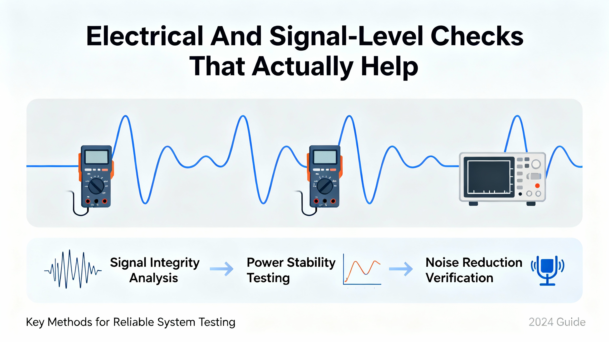
Once the machine is safe and you have a hypothesis, you do need to get quantitative. Several sources, including CBM ConnectŌĆÖs piece on vibration sensor validation and WF SensorsŌĆÖ troubleshooting guide, outline practical techniques that apply well to Pepperl+Fuchs sensors.
First, verify basic power and grounding. JiweiŌĆÖs fieldŌĆæinstrument article recommends starting with the power supply, confirming that the voltage is in the normal range and stable. Many nuisance alarms and intermittent faults trace back to sagging or noisy DC supplies rather than failed sensors. In a PLC cabinet, it is common for multiple sensors and actuators to share a 24 VDC bus; if a single short or overload drags that bus down, several devices will misbehave.
Next, check continuity and insulation in the cable run. WF Sensors recommends using a multimeter to confirm that conductors are neither open nor shorted to each other or to shield, and that resistance values fall within expected ranges. MetrolŌĆÖs failure investigations using XŌĆærays show that pulling or sharply bending cables can break internal solder joints or insulation even when the outer sheath looks fine.
For vibration and other conditionŌĆæmonitoring sensors, CBM Connect highlights the value of looking at the bias output voltage. Many accelerometers export a DC bias level when powered. An ŌĆ£open biasŌĆØ fault shows up as the bias sitting at or near the supply voltage, which suggests a broken or disconnected sensor amplifier. A ŌĆ£short biasŌĆØ fault gives a bias near zero, often due to a cabling short or power failure. Values in between but out of spec typically indicate sensor damage from temperature, mechanical shock, improper powering, or electrostatic discharge. Trending this bias in an online system is a powerful way to detect developing problems in cabling or sensors.
TimeŌĆæwaveform and spectrum analysis are also useful. CBM Connect notes that clipped or flattened waveforms point toward overload or poor connections, while a spectrum with a huge lowŌĆæfrequency ŌĆ£ski slopeŌĆØ often indicates distortion or noise. While those examples come from vibration monitoring, the same mindset applies when you look at analog outputs from other Pepperl+Fuchs sensors: avoid trusting a single number without checking whether the signal shape and noise level make sense.
When there is no easy reference sensor nearby, a dataŌĆæscience oriented approach from a Data Science Stack Exchange discussion can help. The suggestion there is to build a simple model that forecasts a sensorŌĆÖs normal behavior over time based on its own history, then treat the residual, meaning the difference between predicted and actual readings, as an anomaly indicator. For many industrial sensors, a straightforward ARIMAŌĆætype forecasting model combined with engineered features like shortŌĆæterm lags and daily cycles is enough to spot unusual behavior without overcomplicating the solution.
Not every ŌĆ£sensorŌĆØ problem is in the electronics. A large share of real failures and false alarms are mechanical, mounting, or environmental, and they often repeat in the same ways across different lines.
MetrolŌĆÖs application notes on position sensors highlight how improper contact direction can destroy accuracy. If you treat a straightŌĆæacting touch switch like a sliding probe by hitting it at an angle, you apply oblique forces that rub and bend the internal shaft. That leads to poor motion, erratic repeatability, and premature failure. The takeaway for Pepperl+Fuchs mechanical or contactŌĆæstyle sensors is to align the approach direction with the design intent and to adjust fixtures so that the plunger is pressed squarely.
Mounting rigidity matters as much as sensor repeatability. Metrol found that jigs that flex under even modest contact forces cause the actuation point to wander. In my experience, a small inductive sensor on a flimsy tab will never produce stable position data, no matter how good its spec sheet is. Ensuring that brackets and mounts are stiff and properly supported is often the cheapest and fastest ŌĆ£accuracy upgradeŌĆØ you can make.
Cable handling is another source of hidden faults. Metrol notes that when cables are routinely bent tighter than their specified minimum radius, pulled during installation, or exposed to chips, the inevitable result is sheath damage, core breakage, and coolant ingress. Respecting bendŌĆæradius specifications, providing strain relief, and using protective coverings in chipŌĆæprone areas dramatically reduces returns. When space is tight around a Pepperl+Fuchs sensor, using a rightŌĆæangle cable option where available and routing it to avoid repeated flexing will extend its life.
Environmental conditions cannot be ignored. SensorTech and DubaiŌĆæSensor emphasize that exposure to extremes of temperature, humidity, and corrosive atmospheres accelerates degradation and drift. For pressure, pH, and conductivity sensors, fouling and chemical attack can rapidly change the measurement characteristics. In those applications, both sources recommend selecting sensors with appropriate protection ratings and materials, and then cleaning them with manufacturerŌĆæapproved procedures, such as mild solvents and nonŌĆæabrasive wipes.
WatertechŌĆÖs guidance on waterŌĆæquality sensors reinforces several simple, actionable signs that cleaning is due: slower response, inconsistent readings, increasing calibration frequency, and visible buildup. Those same cues apply directly to many Pepperl+Fuchs process sensors. If each calibration requires a larger and larger correction, you are most likely dealing with fouling or aging, not a sudden calibration accident.
At the plant system level, there is a growing push to use more structured Fault Detection and Diagnosis instead of relying entirely on technicians noticing something is wrong. A LinkedIn discussion on industrial control systems defines FDD as a staged process: you detect that a fault exists, isolate where it is, identify its nature, and then take recovery actions. A recent MDPI review on Industry 4.0 fault detection notes that this discipline, once rooted mostly in modelŌĆæbased control theory, now increasingly relies on dataŌĆædriven machine learning.
In discrete manufacturing, where Pepperl+Fuchs sensors are heavily used on machine tools, assembly lines, and materialŌĆæhandling systems, this is particularly challenging. The MDPI paper points out that discrete machines have fast, cyclic behavior with lots of transient states, making realŌĆætime FDD harder than in smooth continuous processes. At the same time, the review concludes that combining dataŌĆædriven methods with physical understanding of the machine yields the most robust results.
A complementary paper in Sensors highlights a practical, modelŌĆæbased strategy where multiple fault models are maintained. The process behavior is compared to the outputs of these models, and the absolute error is monitored. When the error exceeds historically derived thresholds, a binary code is generated that indicates which fault model matches the current behavior. This sort of errorŌĆæbased detection maps well onto multiŌĆæsensor systems where Pepperl+Fuchs devices feed into a PLC or DCS.
MeegleŌĆÖs overview on manufacturing fault detection technologies describes how IoT connectivity, AI, and bigŌĆædata analytics come together. IoT gateways pull data from sensors across the line, AI algorithms scan those streams for patterns pointing to upcoming failure, and analytics platforms help trace root causes. A 2025 strategic playbook on sensor selection for maintenance leaders argues that sensors should be chosen and placed based on quantified maintenance goals, asset criticality, and the potential to detect faults early on the soŌĆæcalled PŌĆæF curve, the window between the first detectable potential failure and functional failure.
All of this means that Pepperl+Fuchs sensors are not just on/off devices anymore; they are data sources for predictive maintenance. When you design lines, plan retrofits, or troubleshoot recurring failures, it is worth asking not only ŌĆ£How do I make this sensor work again?ŌĆØ but also ŌĆ£What data could this sensor and its neighbors provide to help us see the next problem before it stops production?ŌĆØ
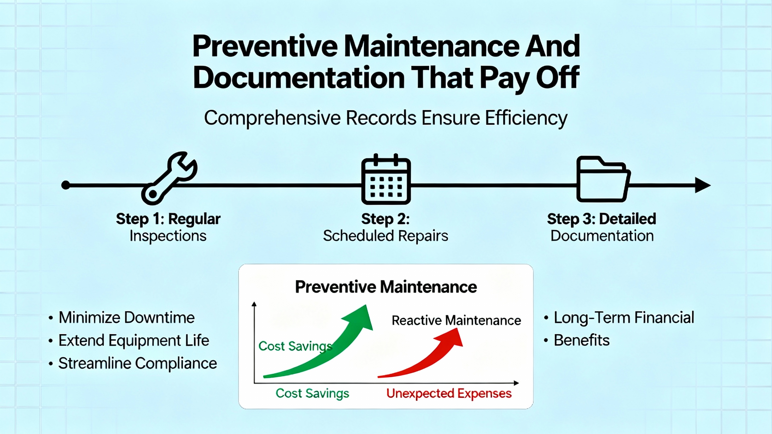
Corrective troubleshooting is only half the job. Virtually every maintenanceŌĆæoriented article in the research notes, from DubaiŌĆæSensorŌĆÖs pressure sensor guide to Turtle ToughŌĆÖs pH sensor documentation, stresses that regular cleaning, inspection, calibration, and documentation are critical to reliability and life cycle cost.
The basic maintenance pattern is consistent. You start with visual inspection for damage, corrosion, leaks, and loose connections. You clean sensing surfaces with compatible agents. You verify calibration against known references at a frequency driven by how fast drift develops under your specific process conditions. DubaiŌĆæSensor explicitly ties maintenance to safety and compliance, arguing that properly maintained sensors keep systems within safe operating limits and avoid regulatory trouble.
Turtle Tough takes this further by describing how to build a drift profile. You periodically compare sensor readings to accurate reference samples and record how quickly they diverge. Once you know how much drift your process can tolerate, you set the calibration interval to stay inside that band. That approach makes far more sense than blindly adopting a generic, fixed calibration schedule for every sensor on a line.
YSIŌĆÖs webinar on online sensor maintenance reframes all of this as a preventative maintenance program. It is not enough to know how to care for each device; you must systematize the tasks, schedule them, assign responsibility, and track completion. YSI demonstrates digital tools that capture maintenance actions, schedule upcoming work, and tie performance trends back to individual sensors. The same philosophy applies if you are managing a large population of Pepperl+Fuchs proximity or analog sensors. Without a disciplined PM program, you will keep fighting the same fires.
Finally, documentation closes the loop. The LinkedIn guidance on troubleshooting automation sensors proposes treating each fault as a data point: log what happened, how you diagnosed it, and what fix worked. Combine that with CMMS or similar systems, as described in ZoidiiŌĆÖs discussion of equipment troubleshooting techniques, and you gain the ability to spot repeat offenders, refine design standards, and justify targeted upgrades in sensors, cabling, or protection methods.
The following table consolidates several of the practical points from Metrol, CBM Connect, Jiwei, WF Sensors, and others into a compact reference you can adapt for Pepperl+Fuchs sensors in your own plant.
| Symptom | Likely Cause Cluster | Practical Field Checks |
|---|---|---|
| Sensor LED off, no output change | No power, overcurrent damage, open cable, failed electronics | Measure supply voltage, check BOV where applicable, verify continuity end to end |
| Intermittent switching or noisy readings | Loose connector, cable damage, EMI, lowŌĆærigidity mounting | WiggleŌĆætest wiring, inspect cable path, check shielding and grounding, flex jig by hand |
| Reading drifts slowly over days or weeks | Calibration drift, contamination, sensor aging | Compare to reference instrument, inspect and clean sensing face, review drift history |
| Frequent false alarms with no real fault | Thresholds too tight, unstable power, process noise | Review alarm settings, log supply stability, analyze trend data for actual anomalies |
| Sensor survives but accuracy deteriorates | Oblique mechanical loading, jig deflection, repeated shocks | Check alignment of contact direction, stiffen or redesign brackets, inspect for dents |
| Several sensors fault at once | Common 24 VDC issue, shared cable tray damage, grounding error | Check DC supply health, inspect shared cable routes, review recent modifications |
Use this table as a starting point, then customize it based on the Pepperl+Fuchs technologies and sensor families you deploy in your facility.
Start by reproducing the symptom with the machine in a controlled condition. If a sensor input on the PLC indicates a problem but the physical process looks normal, check thresholds, scaling, and logic. Jiwei and Glomacs both warn that poorly chosen alarm limits and configuration errors can cause constant alarm behavior. Confirm power and wiring first, then validate configuration against the datasheet and application requirements before replacing hardware.
If cleaning and recalibration do not bring the reading back within your process accuracy requirement, or if the bias or output signal remains unstable, the sensor is no longer fit for service. Jiwei, DubaiŌĆæSensor, and Turtle Tough all recommend prompt replacement when drift or damage exceeds acceptable limits, especially for critical pressure or chemicalŌĆæmeasurement sensors. For inexpensive discrete sensors, if you see recurring faults from the same device after you have corrected installation issues, replacement is usually the most costŌĆæeffective choice.
Metrol and WF Sensors both emphasize respecting bend radius, avoiding tension, and protecting cables from mechanical damage. In practical terms, give yourself generous cable length, route cables where they will not be crushed or repeatedly flexed, use rightŌĆæangle connectors where space is limited, and specify protective coverings or conduits in harsh environments. Periodic visual inspection and continuity checks during shutdowns will catch many developing issues before they turn into hard faults.
In the field, Pepperl+Fuchs sensors are dependable workhorses, but they can only be as reliable as the power, mechanics, environment, and maintenance program you wrap around them. If you treat sensor troubleshooting as a disciplined process rather than a guessing game, back it with solid documentation and preventative maintenance, and use your data to refine where and how you deploy sensors, you will spend far more time improving throughput and far less time chasing ŌĆ£mysteryŌĆØ faults on the line.


Copyright Notice © 2026 mooreautomated.com All rights reserved,Moore Automated is not an authorized distributor or representative of the manufacturers featured on this website. Brand names and trademarks featured are the property of their respective owners.


Leave Your Comment