


MP 3009X
Get A Quote
Motion control is where precision meets production pressure. When a Rockwell Automation axis trips or a motion instruction refuses to complete, a line full of good parts can turn into downtime within seconds. IŌĆÖve stood at HMIs with operators waiting, drives warm, products queuing, and the clock translating minutes into dollars. This playbook compresses what works on the plant floor: a disciplined troubleshooting method, deep familiarity with Rockwell diagnostics, and practical fixes for the mechanical, electrical, and software interactions that cause motion to fault. It blends onŌĆæsite experience with proven guidance from Rockwell documentation, Control Engineering, DigiKey TechForum, Automate, PMD Corp, ACS Industrial, JHFoster, Industrial Automation Co, EC&M, ICA, HySpeco, and other reputable industry sources.
A motion controller error is not a single thing; it is a symptom expressed through several layers of diagnostics. Drives report electrical events such as undervoltage, overcurrent, or thermal trips. Controllers and function blocks surface control-layer problems such as control error, unexpected state transitions, or invalid command parameters. Applications contribute their own interlocks and limits that can look like motion faults even though motion hardware is behaving as commanded. In Rockwell environments this often surfaces as a Studio 5000 axis fault, a rung that never reasserts a motion instruction, a ControlLogix motion routine stuck in an intermediate state, or a Micro800 function block reporting a nonzero error ID. Rockwell documentation for Studio 5000 Logix Designer on motion faults and Rockwell knowledgebase articles for Connected Components Workbench error IDs are the primary references for decoding these conditions. Understanding which layer raised the complaint determines whether you reach for a torque wrench, a scope trace, or a laptop first.
Troubleshooting begins with safety and ends with documentation. DigiKey TechForumŌĆÖs guidance on lockout/tagout, OSHA compliance, PPE, and working with a partner is not academic; motion hardware can hurt people when complacency creeps in. For fast signals, take care not to overŌĆæinterpret indicator LEDs on a PLC or module; they are useful for slow signals but can miss pulses entirely. Before touching a parameter, organize your evidence. Ask operators for precise times, positions, and precursor actions. JHFoster recommends correlating those timestamps with controller logs and historians, then adding shortŌĆæterm data loggers or even video and audio capture for intermittents. MidŌĆæAtlantic Controls emphasizes physically verifying equipment because screens can normalize away small lies; loose connectors, a cracked ferrule, or a miswired sensor will not show up in a trend unless someone looks. Maintain a live service log. If your site lacks SOPs or checklists, write them. You will thank yourself on the next shift change.

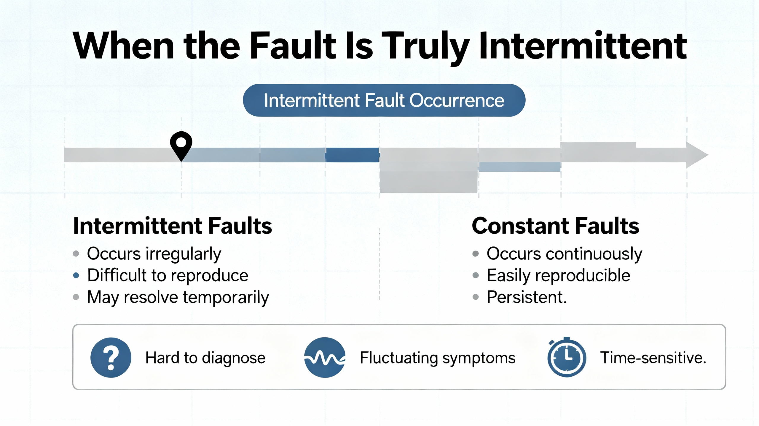
The NavyŌĆÖs sixŌĆæstep method from DigiKey TechForumŌĆÖs NEETS material translates cleanly to industrial motion. Recognize the symptom precisely. Elaborate it with context and boundaries. List likely faulty functions rather than diving into the nearest cabinet. Localize to a specific block by tests planned to disprove hypotheses. Trace the problem to the circuit or configuration. Then perform failure analysis, including the cause that broke it and the record that prevents a repeat. AutomateŌĆÖs excellent advice on intermittent fault isolation is crucial here: ask what changed, differentiate software from hardware by repeatability and environment sensitivity, and pick instrumentation that captures the moment of failure. Avoid the ŌĆ£no problem foundŌĆØ trap that accompanies swapŌĆæandŌĆæhope repairs. The work you put into repeatability and evidence pays itself back during the next outage.
Rockwell motion diagnostics are rich if you read the bits as the controller intended. A common snag is misunderstanding instruction state bits on position moves. Community experience documented on mrplc.com explains that the Motion Axis Move (MAM) instructionŌĆÖs .PC and .DN bits do not clear identically. The .DN bit clears in the instructionŌĆÖs preŌĆæscan before the next execution, but the .PC bit can remain set until the rung makes a clean falseŌĆætoŌĆætrue transition. Engineers who latch state machines solely on .PC risk cycles that never reŌĆæarm because the program never went false. One reliable pattern is to pair .EN with .PC or use .PC with NOT .IP to infer completion, and to enforce a rungŌĆæfalse period between cycles. RockwellŌĆÖs Studio 5000 help clarifies bit semantics; read it alongside your logic.
| Bit | Meaning in practice | Clears when you do the right thing |
|---|---|---|
| .EN | Instruction enabled while rung is true | When the rung goes false and the instruction deŌĆæenergizes |
| .IP | In progress; axis moving or executing the profile | When motion completes or is aborted |
| .DN | Done; completion detected this execution | During the instructionŌĆÖs preŌĆæscan before the next execution |
| .PC | Program complete; often persists across scans | After the rung transitions from false to true and the instruction is reŌĆæarmed |
On Micro800 platforms, CCW motion function blocks raise error IDs that map to specific conditions. The official Rockwell support mapping for these IDs is the authority; use it to move from an opaque number to a precise fix. For Studio 5000 axis faults, the builtŌĆæin motion faults pages document categories and recovery actions. When in doubt, favor the vendor help first, then your own ladder or Structured Text second.
When production pressure closes in, a repeatable sequence cuts resolution time. JHFoster outlines an order that aligns with field results. Start with hardware. Verify power distribution, fuses and starters, rails and screws, belts, chains and gears, and notched shaft keys or shear pins. Cables fail more often than drives and often fail only under motion; flexŌĆæcycle fatigue breaks copper strands invisibly. Swap motor power and encoder cables with knownŌĆægood sets and test again. If the symptom disappears, replace the cable and throw away the old one. Only after cable checks turn up clean should you suspect the feedback device. Encoders and resolvers can lose home or crash out of alignment; recalibrate home, then test with a knownŌĆægood encoder. After feedback passes, look at the motor for bearings, brake issues, or crash damage. Only then should you turn to software, firmware, and the drive. Unless you just changed a program or a revision, the controller is rarely the first thing to fail. In any crash, assume secondary damage; treat couplings and keys as suspects until proven good.
Many soŌĆæcalled motion errors are actually control limit cycles. An instructive case from the Automation & Control Engineering Forum describes a servo axis that hunts around the setpoint within a small deadband because the driveŌĆÖs finite minimum velocity and a drive dead zone prevent small commands from moving the axis. The integral term ramps up, the axis breaks static friction, overshoots, and repeats. A lookup table reduced period but did not remove the cycle. PMD CorpŌĆÖs engineering notes add that high derivative gain amplifies noise and that separate parameter sets for moving versus holding states can keep a servo quiet at hold. Translating this into practical fixes yields a pattern you can apply on Rockwell motion:
These remedies are not theoretical. They explain why a small integrator hold at zero and a tiny controlled dither will quiet an axis that otherwise bounces forever between plus and minus one count, and why lowering derivative in a noisy system often makes the system both quieter and more robust.
Kinetix drives are high performance, but they are only as good as the assumptions that feed them. Industrial Automation Co highlights six mistake families that create downtime and erratic motion. If your axis faults when a product changes weight, your model probably ignored dynamic load. Run a dynamic load analysis with a tool such as RockwellŌĆÖs Motion Analyzer and reŌĆæsize torque and inertia parameters to match real operation. If your cabinet runs hot, expect thermal derates or sudden shutdowns; spacing, forced ventilation, heat sinks, and monitoring builtŌĆæin thermal sensors should be a design feature rather than an afterthought. Feedback is fundamental; miswired or mismatched encoders produce jitter, position loss, and desynchronization. Calibrate, match devices, and verify alignment with autoŌĆætuning. Skipping firmware updates invites incompatibilities and closes the door on diagnostic improvements; Rockwell revision tools exist to help you plan those upgrades and validate them in a controlled window before rollout. On multiŌĆæaxis systems, EtherNet/IP latency can desynchronize coordinated motion; choose lowŌĆælatency industrial switches, isolate the motion network, and use Integrated Motion over EtherNet/IP to maintain realŌĆætime behavior. Wiring and grounding are not paperwork details. Separate communication conductors from motor power cables to reduce electrical noise, follow manufacturer routing guidelines, and audit grounds for highŌĆæfrequency stability.
Several manufacturers emphasize the operating environment because it quietly degrades motion long before faults appear. ACS Industrial recommends shielding against electrical noise, adding noise filters, and physically isolating sensitive components. Temperature is not a suggestion; keep it stable with insulation, heating, or cooling to prevent controller drift. Contaminants in the air end up in bearings and guides; enclosures and filtration reduce unplanned downtime. Calibration and alignment schedules preserve multiŌĆæaxis coordination. Preventive maintenance guidance from ICA, HySpeco, and Process Industry Forum converges on the same habits: inspect and clean regularly, torque electrical terminations, lubricate per manufacturer schedules, calibrate sensors and control loops, apply software updates and security patches, replace wear items on a schedule, and keep both offline and offsite backups so configuration and data survive the worst day. EC&M reminds us that motor control centers live hard lives as power hubs; thermal and electrical stresses loosen terminations and age insulation. Follow manufacturer maintenance intervals, keep oneŌĆælines and settings current, and stock critical spares to reduce recovery time. These practices do more than keep lights green; they eliminate the root causes of chattering encoders, intermittent undervoltage trips, and flaky I/O that motion routines inherit as ŌĆ£errors.ŌĆØ

The following table is a fieldŌĆætested way to map symptoms to likely causes and the next action. It compresses the guidance above into a form you can work through at an HMI or with a laptop on your cart.
| Symptom in the cell | Likely cause to test first | Action that most often clears it |
|---|---|---|
| Axis hunts near setpoint in tiny steps or counts | Static friction, amplifier dead zone, integrator windup | Reduce integral gain near zero, add integral deadband or conditional integration, introduce small dither, consider creep mode into hold; reŌĆætune P and D as needed |
| Motion faults intermittently with control or following errors after long cycles | FlexŌĆæfatigued power or encoder cable, loose connector | Swap with knownŌĆægood cables, reseat connectors, replace if symptom disappears; reŌĆætest under motion to confirm |
| MultiŌĆæaxis sync slips at higher throughput or during line disturbances | EtherNet/IP latency, shared network congestion | Use lowŌĆælatency industrial switches, isolate motion network segments, enable Integrated Motion over EtherNet/IP, verify switch specs and topology |
| Drive overtemperature or unexpected thermal shutdowns | Poor cabinet airflow or spacing, high ambient | Improve airflow and spacing, add forced ventilation or heat sinks, monitor thermal sensors, revisit enclosure design |
| State machine never reŌĆæarms after a successful move | MAM .PC remained set because rung never went false | Force a rungŌĆæfalse period between cycles, pair .EN with .PC or use .PC with NOT .IP, reŌĆæarm with a clean falseŌĆætoŌĆætrue transition |
| Random trips with ŌĆ£no problem foundŌĆØ after part swaps | External influences, ground loops, power sag or spikes | Instrument with triggers, capture supply voltage, motor current, and speed traces, correlate with neighbor equipment events; add isolation or filtering where indicated |
Intermittent faults are where good engineering pays the bills. AutomateŌĆÖs troubleshooting guidance recommends a twoŌĆæstaged mindŌĆæset. Use inductive reasoning to enumerate plausible causes, then deductive tests to crush them one by one. Instrumentation is not optional. BuiltŌĆæin or software oscilloscopes with pre/post triggers can log a halfŌĆæsecond of supply voltage, motor current, and speed at the very moment the controller raised an undervoltage, overcurrent, or control error. Stress the system by varying power, flexing cabling, and gently warming or cooling suspect boards. Inject a little radio energy using a handheld transmitter near boards to expose marginal shielding. If a software hypothesis exists, revert to a knownŌĆægood version and bisect. Hardware faults tend to be environmental and repeat with vibration or heat; software faults repeat on a specific predictable sequence and vanish if you change that sequence. Watch for aliasing and coupling; ghost waveforms that stretch across systems often point to sampling or layout rather than a mysterious new physics. Shared power supplies and neighboring equipment on a common bus are famous for injecting solenoid kickback into sensitive electronics; an isolation transformer or better catch diodes can make a ŌĆ£hauntedŌĆØ axis behave again.
Drives and controllers do not wake up one morning and decide to change personality. The risk you own is in unmanaged changes. Industrial Automation Co points out that skipping firmware and ignoring diagnostics produce preventable compatibility headaches and missed early warnings. Plan revision updates with vendor tools, document your tested combinations of controller, drive, network switches, and firmware, and roll out in a controlled window. EtherNet/IP foundations matter. For integrated motion, treat network design as part of control design. Keep motion traffic off generic plant switches, use devices that advertise and meet lowŌĆælatency performance, and isolate noisy workcells from precision motion where practical. These choices pay back when a multiŌĆæaxis pickŌĆæandŌĆæplace stops tripping at random after the packaging line next door starts a highŌĆæpower solenoid.
The fastest troubleshooting on the worst day starts with habits on good days. ICA emphasizes a comprehensive maintenance schedule, staff training, and clean documentation; HySpeco adds practical steps like tightening electrical connections, scheduled calibration, and clear spares strategies; Process Industry Forum lists the handsŌĆæon details from valve internals to strainer screens and cap gaskets that keep loops honest. EC&MŌĆÖs overview of MCC practices is a reminder that motion control sits on top of power hardware that deserves the same rigor. MidŌĆæAtlantic Controls advocates checklists and thorough records so technicians can plan access for hardŌĆætoŌĆæreach devices rather than improvising on a lift at 2:00 AM. All of this frames your Rockwell troubleshooting: when your documentation is current, your backups are recent, your spares are on the shelf, and your SOPs are trained, ŌĆ£fault clearedŌĆØ is measured in minutes, not hours.

After you find and fix the root cause, prove it. Run the process through the exact sequence that failed. Trend key signals at the controller and, if available, in a historian for a few hours. Revisit the operators and confirm the symptom is gone. Write the service entry with the evidence, the hypothesis you disproved, the final cause, and what would have prevented it. Update SOPs, logic comments, and training materials. If you leaned on a vendor knowledgebase or vendor documentation for a code or a bit behavior, cite it in your notes so the next engineer sees the path you took. Back up the program to both your engineering repository and your offsite backup. Close the loop by scheduling any followŌĆæon work you deferred to get running, such as adding a small dither, separating a cable bundle, replacing a connector across the line, or bringing in a higherŌĆæefficiency motor to lower heat in a tight cabinet as suggested by RS industry guidance on lifecycle energy costs.
What is the practical difference between .PC and .DN on a Rockwell MAM instruction? The .DN bit signals completion on the current execution and clears during the instructionŌĆÖs preŌĆæscan prior to the next execution. The .PC bit reflects programŌĆælevel completion and tends to remain true until the rung goes false and then transitions true again. State machines should either combine .EN with .PC or assert a rungŌĆæfalse period between cycles so completion is not latched forever.
Should I disable the integrator near zero to stop hunting? Yes, but deliberately. A small integral deadband or conditional integration near zero prevents windup when the actuator sits in a dead zone or static friction holds it. Pair this with a tiny dither or a controlled creep speed into hold, then retune P and D so you do not amplify noise. This approach is consistent with control theory and industry recommendations shared by PMD Corp and forum case studies.
How do I decide if my multiŌĆæaxis sync problem is network related? If the issue appears only at higher throughputs or when unrelated equipment on a shared network runs, suspect EtherNet/IP latency. Isolate the motion segment, use lowŌĆælatency industrial switches, verify integrated motion configurations, and retest. If the symptom disappears or shifts with topology, treat network design as part of the fix rather than as a variable to work around.
What evidence should I capture before calling Rockwell support? Grab the controller project, axis fault history, drive diagnostics, and a short oscilloscope trace with pre/post triggers of supply voltage, motor current, and speed near the event as suggested by Automate. Add a service log entry with exact timestamps, operator observations, and any recent changes in process, hardware, or software.
On a busy line, you do not need folklore; you need a method you can run at 3:00 PM on a Tuesday or 3:00 AM on a holiday weekend. Read the bits the way Rockwell designed them, start with hardware you can touch, instrument what you cannot see, and tune with intent rather than hope. Treat power, networks, and the environment as part of motion, because they are. Do this consistently and motion controller errors become teachable moments, not productionŌĆæstoppers. As an onŌĆæsite problem solver, thatŌĆÖs the standard I hold myself toŌĆöand the standard your line deserves.


Copyright Notice © 2026 mooreautomated.com All rights reserved,Moore Automated is not an authorized distributor or representative of the manufacturers featured on this website. Brand names and trademarks featured are the property of their respective owners.


Leave Your Comment