


MP 3009X
Get A Quote
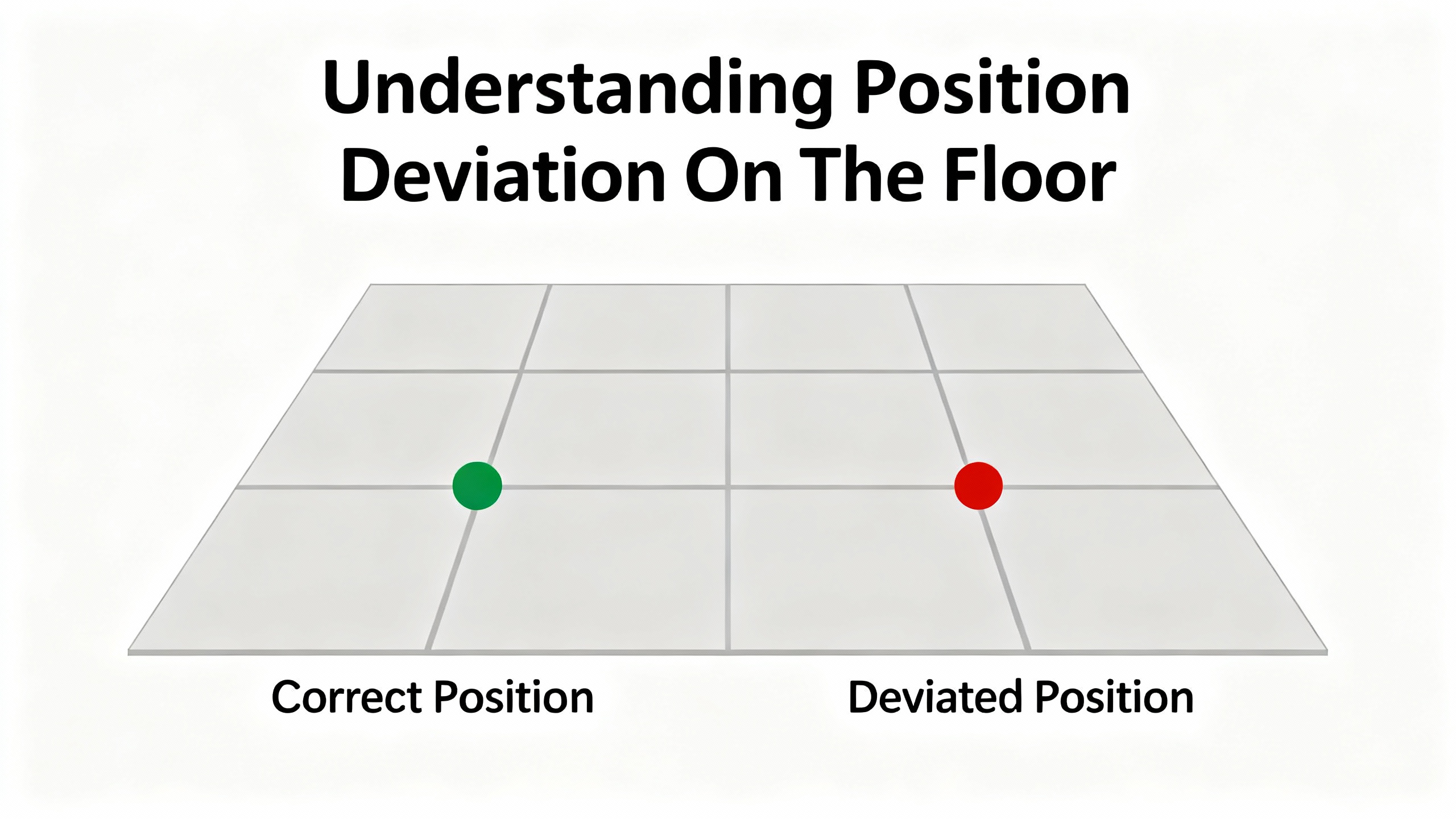
Position deviation alarms on a Yaskawa servo drive are one of those faults that look ŌĆ£mysteriousŌĆØ from the HMI, but on the plant floor they are very physical: a pick head landing off target, a seal jaw clipping a product, or a robot joint that no longer lines up with its fixture. In practical terms, a position deviation error means the drive does not believe the motor is where the controller says it should be, and the deviation has crossed a trip threshold.
From years of commissioning and fixing Yaskawa-based lines in packaging, CNC, and assembly, I have learned that these errors are rarely ŌĆ£just tuning.ŌĆØ They sit at the intersection of feedback integrity, signal quality, mechanics, and drive configuration. The good news is that Yaskawa drives are very transparent if you know how to read their alarms and data, and the same root causes show up again and again.
This article walks through how Yaskawa drives think about position deviation, what common symptoms really mean, and a systematic way to troubleshoot and prevent these errors, drawing on published fault-code guides, industrial repair houses, and real-world field experience.
Servo drives in general regulate torque, speed, and position in a closed loop using feedback devices such as encoders or resolvers. Sources such as BIN95 and InRobots describe the drive as a controller that takes position commands from a PLC or motion controller, compares them against actual position from the encoder, and then drives the motor to reduce the error.
Roc Industrial, which specializes in Yaskawa repair, defines position error as the driveŌĆÖs inability to maintain the commanded position because of feedback, tuning, or parameter issues. In Yaskawa terminology this shows up under several alarm families often labeled as ŌĆ£position error,ŌĆØ ŌĆ£excessive position deviation,ŌĆØ ŌĆ£out-of-control detection,ŌĆØ or ŌĆ£overtravel due to deviation.ŌĆØ
Yaskawa fault-code compilations summarized by VIYORK show that:
Position and motion deviation alarms such as A.d00ŌĆōA.d02, A.d30, A.900ŌĆōA.901, and A.9A0 are triggered when the difference between the commanded and actual position exceeds an allowable range or leads to overtravel.
Related alarms like A.C10 indicate out-of-control detection, and A.510 reports overspeed, often appearing alongside deviation problems when the drive cannot track the commanded motion.
The exact behavior depends on the series and parameters, but the principle is the same: the drive constantly calculates position error, allows a certain following error band during motion, and trips when that error grows too large for too long. This protects the mechanics and product from uncontrolled motion.
To make this concrete, it is useful to frame the key concepts in plain terms.
| Term | In practice on the machine |
|---|---|
| Commanded position | Where the PLC or motion controller expects the axis to be, based on its own position calculation. |
| Actual position | Where the encoder or resolver says the motor (or load) really is, as measured by the servo drive. |
| Position deviation/error | The difference between commanded and actual positions inside the drive. |
| Following error band | The window of acceptable deviation during motion before the drive raises a warning or alarm. |
| Position deviation alarm | A drive trip because deviation exceeded a threshold, either dynamically or at standstill. |
A healthy system keeps deviation small and bounded. A drifting or noisy system lets that error accumulate until YaskawaŌĆÖs protection logic steps in.
Yaskawa error lists collected and summarized by VIYORK show that deviation-related issues are not represented by a single code but by families of alarms. While you must always check the manual for your specific model, the pattern is consistent.
Position deviation alarms A.d00ŌĆōA.d02 and A.d30 point to excessive position error, often linked with speed limits or motion constraints.
Codes A.900ŌĆōA.901 and A.9A0 are associated with overtravel and position deviations that push the axis beyond its allowed range or limit settings.
Alarm A.C10 is an out-of-control detection signal, reported when the drive detects that the servo loop is no longer controlling position adequately.
Overspeed error A.510 indicates that the motor is turning faster than the configured maximum speed, which can show up when feedback polarity or scaling is wrong and can coexist with deviation alarms.
Alongside these, Yaskawa drives also raise encoder and temperature alarms (for example, encoder faults and overheating coded in the A.810ŌĆōA.891 and A.861 ranges) that often sit ŌĆ£upstreamŌĆØ of position deviations. An encoder that intermittently fails will not always give you a neat ŌĆ£encoder error only.ŌĆØ Instead, you see position deviation alarms, oscillation, or overspeed, and only occasionally a dedicated encoder alarm.
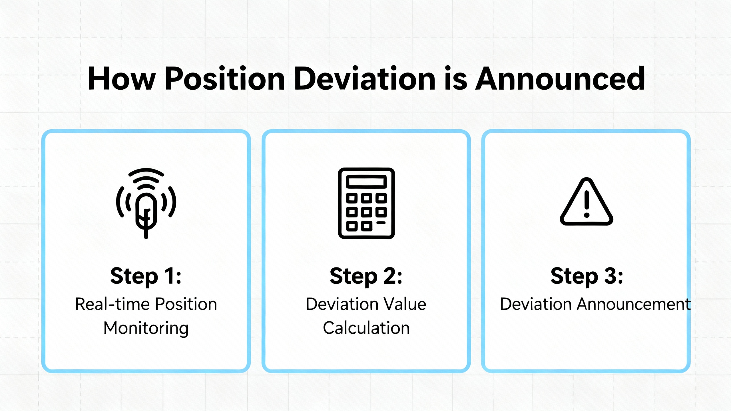
The first pragmatic move on site is simple: write down the exact Yaskawa alarm codes and any axis-common warnings, and check how often they appear in the driveŌĆÖs history. Industrial Automation Co. emphasizes starting with the code definitions and a structured fault history before you touch wiring or tuning, and that aligns perfectly with what works in the field.
Although the drive speaks in alphanumeric codes, operators and maintenance techs usually describe the problem in mechanical terms. Several real-world patterns show up repeatedly.
On pick-and-place or dispensing equipment, a calibration that starts dead-on begins to drift over a shift. A clean-room pick-and-place example captured by Elektroda shows an axis calibrated at roughly one position slowly ending up close to half an inch off after many continuous cycles, even with stable ambient temperature. Logs revealed that the number of commanded pulses from the controller did not match what the servo drive received, pointing away from ŌĆ£software bugŌĆØ and toward signal integrity problems.
In other cases, the axis runs normally until it approaches a particular position, then the Yaskawa drive trips on position deviation or overspeed just as the motion slows. VIYORK reports low-speed crawling and oscillation when system gain is set too low or too high, and alarm No.16 on some MHMA digital AC servo systems when excessive gain leads to self-excited oscillation. These tuning issues manifest as chattering near the end point and drive trips when deviation spikes.
Sometimes the complaint is more basic: ŌĆ£the servo keeps losing position.ŌĆØ Roc Industrial notes that position error often comes with stalling, vibration, or failure to hold a commanded point. Industrial Automation Co. sees similar patterns when encoder feedback is unreliable or when communication between controller and drive is unstable.
Finally, in harsh environments the position deviation may be the last thing you see before more dramatic failures. Industrial Monitor Direct describes Yaskawa SGDH drives that repeatedly trip on overcurrent (A.10) due to motor shorts caused by oil and vapor ingress. In those plants, damaged internal components and repeat trips are the visible symptom of an underlying environmental and motor-insulation problem. Even when the drive still moves the axis, accumulated damage and unstable current can show up first as poor positioning.
Understanding which of these patterns you are facing is critical, because the root causes and priorities are very different.
In modern Yaskawa systems using pulse-train or similar position commands, the drive expects precise, noise-free pulses. The Elektroda case showed a clear mismatch between pulses sent by the controller and pulses counted by the Yaskawa drive, with one experienced practitioner claiming that the overwhelming majority of such drift cases they see are caused by AC mains noise coupling into the pulse wiring.
When electrical noise corrupts the pulse train, two things happen. The controller believes the axis is at the ŌĆ£correctŌĆØ position based on the pulses it issued. The driveŌĆÖs internal position counter, however, misses or miscounts pulses and ends up with a different coordinate. The drive then raises position deviation alarms or you see gradual drift that you cannot explain by mechanics or temperature.
The same thread and other industrial guidance recommend a classic set of noise-mitigation measures: install an AC line noise filter on the panel supply, physically separate AC power and low-level DC or pulse cables, keep pulse runs as short as feasible, twist the CW and CCW pairs, and use shielded cable with proper single-point grounding. Ferrite beads on noisy lines can also damp high-frequency interference. Industrial Automation Co. adds that communication faults in general should be approached systematically by checking cables, verifying protocol parameters, and ruling out EMI sources before replacing hardware.
In practice, when I see a clean mechanical system with gradual drift and Yaskawa deviation alarms, I treat signal integrity as the prime suspect before reaching for the gain parameters.
Encoder and resolver problems are a classic source of position deviation. VIYORKŌĆÖs Yaskawa fault-code summaries list entire ranges of encoder-related alarms, covering wiring faults, data errors, calibration issues, low encoder-battery voltage, and communication failures between encoder and drive.
Industrial Automation Co. stresses that encoder feedback errors can arise from loose or broken connections, mechanical misalignment of the encoder, or damage to the encoder itself. Mitchell Electronics, which focuses on servo motor troubleshooting, adds that damaged encoder cables, connectors, or disks manifest as positioning errors and unstable motion.
In the field, an encoder that is starting to fail does not always produce a neat, repeatable encoder alarm. Instead you may see intermittent position trips, random overspeed alarms, or a motor that occasionally ŌĆ£jumpsŌĆØ while the commanded trajectory is smooth. If the encoder is shaft-mounted or uses a coupling, any slip on that coupling will cause the encoder to report a position that differs from the actual load.
Feedback polarity is another source of trouble. VIYORK notes that incorrect speed-feedback polarity, or miswired encoder phases, can lead to stalling and erratic motion; swapping encoder lines or Hall signals and confirming the 5 V encoder supply and reference are standard corrective actions.
Whenever I face unexplained position deviation alarms, one of my first tests after mechanical inspection is to examine the encoder wiring and connectors under magnification, pull on each conductor, and verify the encoder supply voltage and ground reference right at the motor.
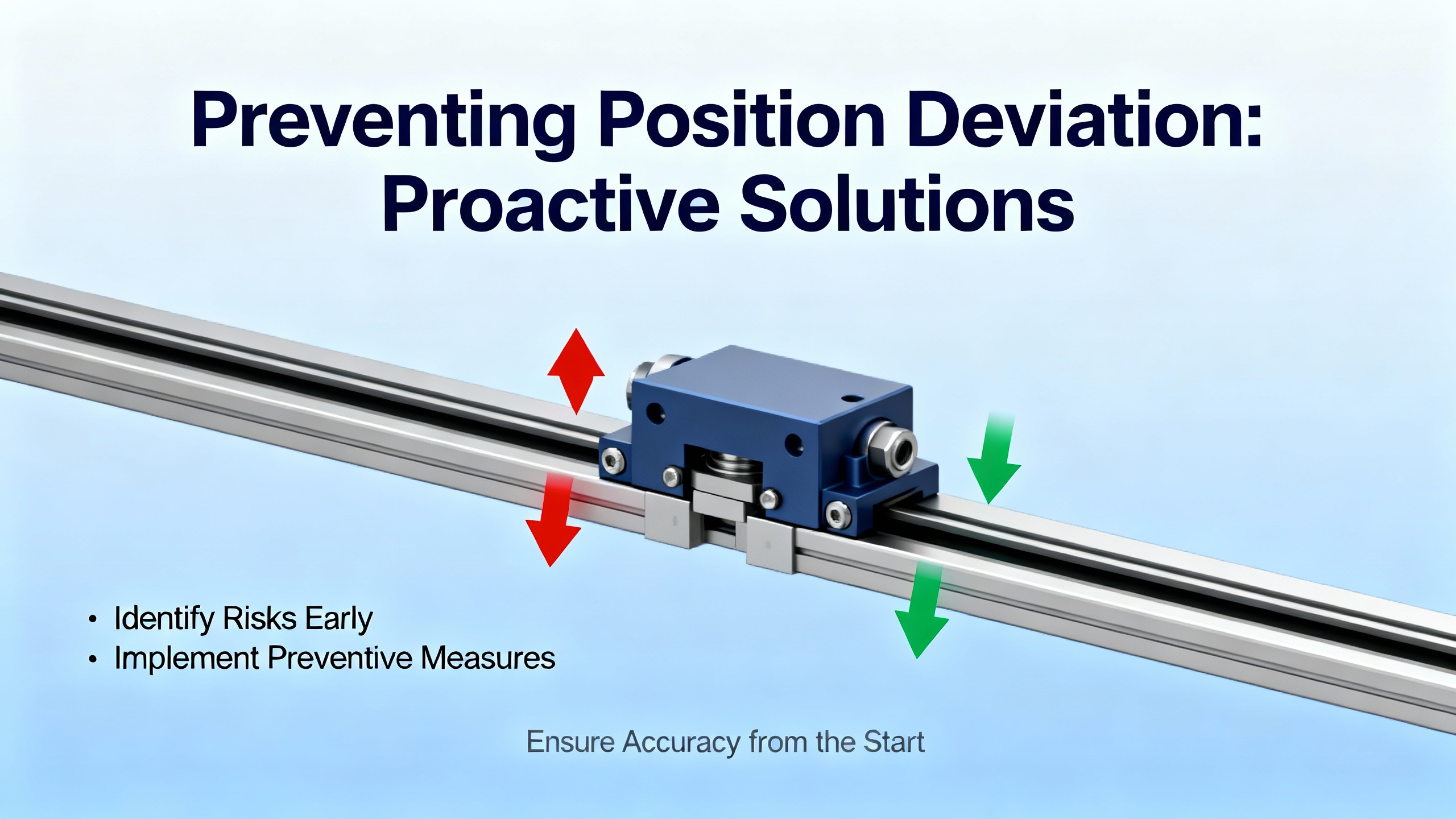
No amount of tuning can overcome mechanics that move independently of the motor. THM Huade describes servo motor alignment as the precise matching of the motor shaft to the driven load, warning that misalignment causes vibration, heat, premature bearing wear, torque loss, and poorer positioning accuracy. They also point out that misalignment symptoms include unusual noise, excessive vibration, overheating of the motor housing, and reduced positioning accuracy.
Electroda practitioners remind us that belt slip, loose couplings, worn pulleys, and weak return springs can all cause the tool point to drift away from its nominal zero position over many cycles. This is particularly insidious when the mechanism settles in a new ŌĆ£soft zeroŌĆØ without obvious noise or alarms until the deviation accumulates to the trip threshold.
The solution is mechanical discipline. THM Huade recommends shutting down and electrically isolating the system, cleaning and leveling mounting surfaces so the motor is not distorted, using proper alignment tools to correct angular and parallel misalignment, verifying that flexible couplings are correctly sized and installed, then retesting at low speed and recalibrating while monitoring vibration.
Even in smaller systems, the principle holds. A comment from an Ikon flybarless discussion on RC helicopters emphasizes physically adjusting servo arms to align travel instead of relying solely on electronic trim. In industrial terms, that translates to centering mechanics and coupling positions first, then using software offsets sparingly. If your axis only hits its mark with large electronic offsets, you have mechanical trouble waiting to happen.
Poor tuning can turn a marginal system into one that constantly trips on position deviation. VIYORKŌĆÖs examples with MHMA digital AC servos illustrate two extremes. With gain set too high, the system experiences self-excited oscillation at power-on and raises alarm No.16. With gain set too low, the motor ŌĆ£crawlsŌĆØ at very low speed, alternating speed-up and slow-down cycles instead of moving smoothly.
PMDŌĆÖs discussion of common motion problems explains that dynamic tracking error, not just final position error, matters in many applications. High servo gains reduce tracking error but increase the risk of oscillation; lower gains improve stability but allow more position lag, especially during acceleration and deceleration. Advanced techniques such as velocity and acceleration feedforward, cascaded position and velocity loops, and carefully chosen sampling times help reduce tracking error, but the fundamentals still apply: you must tune the system aggressively enough to follow the commanded path without exciting resonances.
Yaskawa drives often provide auto-tuning and vibration-suppression functions, which can help, but they assume that mechanics and wiring are sound. VIYORK notes that vibration-related alarms and auto-adjustment errors are often hints that mechanical rigidity is insufficient or that couplings and mounting need improvement, not that you should blindly raise or lower gains.
A practical rule I use is simple. If the axis drifts slowly and quietly, look at noise, feedback, and mechanics first. If it chatters, hums, or oscillates near the end of the move and trips on deviation or overspeed, then bring tuning and mechanical stiffness to the front of the investigation.
Multiple sources, including BIN95 and InRobots, emphasize that overheating, power quality issues, and poor grounding are among the most common causes of servo drive failures. Overvoltage and undervoltage alarms, overcurrent trips, and internal power-supply faults can all show up in YaskawaŌĆÖs main-circuit and power-supply alarm ranges summarized by VIYORK.
Industrial Automation Co. notes that overvoltage can be caused by a supply that is too high or by regenerative energy raising the DC-bus voltage during aggressive deceleration. Their recommendation is to verify supply voltage, consider installing a braking resistor, and optimize deceleration. Undervoltage errors are typically linked to drops in input power, failing power supply components, or loose wiring.
From a position-deviation standpoint, unstable power and poor grounding do two things. They create intermittent resets and brownouts that cause axes to stop mid-travel and lose their position reference. They also increase electrical noise and stress on internal components, which then feed back into feedback and communication problems.
InRobots points out that more than a third of servo drive failures stem from poor ventilation or blocked filters, which is a simple maintenance issue. They recommend keeping drive cabinets clean, monitoring temperature, maintaining fans, and replacing them periodically.
When you see a Yaskawa position deviation error combined with power, temperature, or axis-common alarms, treat the electrical environment as seriously as the motion control.
Industrial Monitor Direct describes a tough case in harsh, oily, high-temperature environments using Yaskawa SGDH drives. In these applications, motor shorts caused by oil and steam penetrating through motor shaft seals and housings led to repeated overcurrent alarms (A.10) and burnt ceramic resistors inside the drive. Standard line-side fuses and surge suppressors could not protect the drive from fault currents originating at the motor.
Their root cause analysis highlights two key points. The motor insulation and sealing were not matched to the real environment, and operators repeatedly reset overcurrent alarms without addressing the cause, allowing damage to escalate.
Their recommendations are very pragmatic. Mechanically, install proper shaft seals on all motors to prevent oil ingress, consider low positive-pressure kits around three psi in heavy vapor or oil-mist environments, and verify that motor environmental ratings truly match on-site conditions. Electrically and procedurally, treat overcurrent alarms like A.10 as serious events that cannot be simply cleared. Use the HMI to enforce lockouts after a fault, remove the operatorŌĆÖs ability to endlessly reset critical alarms, and track fault frequency, allowing only a limited number of resets per drive per day. They also explicitly warn against inserting extra fuses between the drive and motor, because this can interfere with the driveŌĆÖs internal short-circuit protection and make failures worse.
They also note that upgrading from older SGDH units to Sigma-5 SGDV drives improved short-circuit protection logic and provided clearer fault indication through codes such as A.100. Combined with shaft sealing and stricter alarm handling, some sites reportedly reduced Yaskawa servo-drive failure rates by more than eighty percent.
While these are overcurrent cases rather than ŌĆ£pureŌĆØ position deviation alarms, in practice the same harsh conditions that damage insulation also corrode connectors, contaminate encoders, and create intermittent faults that first appear as positioning issues. Treat the mechanical and environmental root causes with the same seriousness you give to the electrical ones.
Before touching a Yaskawa drive, follow the safety practices outlined by BIN95, YaskawaŌĆÖs general troubleshooting guides, and others. Lock out and tag out the machine. Wait for DC bus capacitors to discharge fully, which can take several minutes. Use insulated tools and appropriate PPE, and do not megger-test a motor with the drive still connected.
Then capture information. Note the exact Yaskawa alarm codes, any axis-common warnings, and the context: whether the trip happens at startup, during motion, at stop, or randomly. Check the driveŌĆÖs fault history if available, as InRobots and Industrial Automation Co. suggest, to look for patterns rather than isolated events. A recurring pair of alarms, such as an encoder warning followed by position deviation, points you toward feedback; a pattern of undervoltage and deviation alarms during peak load points you toward power.
Clarifying how the axis misbehaves helps narrow the list quickly. If the axis starts correctly but gradually moves off target over hundreds of cycles while the environment is stable, as in the Elektroda pick-and-place case, noise and mechanical slip are prime suspects.
If the axis is consistently off by the same distance after every move, especially after power cycling, you are likely dealing with a homing, reference, or scaling issue, or with mechanical zero shifting.
If the axis tracks acceptably until heavy acceleration, deceleration, or near a specific setpoint, and then trips with a sharp position deviation or overspeed alarm, tuning, mechanical resonance, or travel limits are in play.
PMD emphasizes that dynamic tracking error during motion can matter more than final settling error. Many Yaskawa position deviation faults are triggered dynamically during demanding parts of the profile, not after everything has come to rest.
With power off and the system safely isolated, inspect the mechanics end to end. Check that the motor is firmly mounted and that the base or machine frame is not cracked or warped. Verify couplings, keyways, and clamping hubs are tight and show no fretting or shine that would indicate slip. Inspect belts and pulleys for wear, missing teeth, or contamination; a belt that jumps a tooth will give you a substantial position error in a single cycle.
THM Huade recommends cleaning and leveling the mounting surfaces, correcting angular and parallel misalignment using proper tools, and verifying that flexible couplings are correctly sized. If the axis has a home sensor or mechanical hard stop, confirm that it has not physically shifted. Use alignment marks, dial indicators, or laser tools where appropriate.
If you can release the motor mechanically and move the axis by hand, feel for tight spots, play, or backlash. Any intermittent resistance or slack can translate directly to varying position deviation under servo control.
Next, focus on the encoder. Inspect connectors on both the motor and drive for contamination, loose pins, or bent contacts. Gentle tugging on each conductor can reveal broken strands crimped into a terminal. Mitchell Electronics recommends checking the power supply at the motor terminals with a multimeter to ensure the encoderŌĆÖs supply voltage and ground are within specification and stable.
If your Yaskawa drive is showing explicit encoder-related alarms like Alarm No.22, or encoder backup and communication faults in the A.810ŌĆōA.891 and A.C20ŌĆōA.CC0 ranges summarized by VIYORK, prioritize encoder troubleshooting. Verify the encoder type and wiring match the drive configuration. If possible, view encoder position counts while manually moving the axis slowly; jittering or discontinuous counts are a red flag.
When stalling or unstable motion is accompanied by signs of incorrect feedback polarity, VIYORK suggests swapping feedback lines such as tachometer or encoder phases and confirming the encoder supply and ground reference are correct. Always document the original wiring before making changes.
If the encoder and mechanics check out, return to the command side. In pulse-train systems, use the controllerŌĆÖs diagnostics to verify that it is outputting pulses in the expected direction and quantity. Then examine cable routing. Separate AC mains and motor power cables from low-level command and feedback cables as much as possible. Avoid running them in the same conduit or bundle.
The Elektroda practitionerŌĆÖs experience that most drift cases stem from AC noise is worth taking seriously. Install an AC line noise filter on the control panel supply if one is not present. Use twisted pairs for CW and CCW or pulse and direction signals. Replace any generic unshielded cable with shielded cable rated for industrial motion control and ground the shield at a single point as recommended.
Ferrite beads or cores on noisy lines can help suppress high-frequency interference. Industrial Automation Co. also recommends checking communication cables and connectors on digital networks and ensuring protocol and parameter settings match between drive and controller.
After making these changes, repeat a long run under the same conditions that previously produced drift and compare the results. Elektroda suggests logging commanded versus received pulses over several hundred cycles, then repeating the test after noise-mitigation steps to confirm improvement.
Once wiring and mechanics are under control, turn to configuration. Yaskawa drives expose numerous parameters that govern control mode, pulse formats, maximum speeds, and gains. VIYORK highlights practical examples. In position-control mode, if the controller sends pulse and direction signals but the motor turns only one way for both forward and reverse, the drive may still be set for quadrature A/B input. They note that setting parameter No42 to select pulse and direction mode resolves this in affected systems.
They also show that excessively high gain parameters such as N.10, N.11, and N.12 in some Yaskawa digital AC servo systems cause self-excited oscillation and alarm No.16. Reducing gain removes the oscillation. Conversely, gains set too low produce low-speed crawling behavior, with the motor speeding up and slowing down at very low speeds. In these cases, increasing gain or enabling automatic gain adjustment helps.
Industrial Automation Co. and MroElectric recommend using the driveŌĆÖs tuning tools and configuration software to review maximum speed limits, acceleration and deceleration profiles, and motion limits. Misconfigured maximum speed parameters can lead to overspeed alarms like A.510, and poorly chosen limits can interact with deviation detection thresholds to create false trips.
Where possible, back up current parameter sets, then compare them against known-good configurations or factory defaults. Restore parameters that are clearly out of range or inconsistent with the motor and mechanics.
At this point, if position deviation alarms persist, re-examine power and grounding. BIN95 and InRobots both stress that voltage fluctuations, loose connections, and poor grounding are major contributors to servo drive issues.
Verify that input voltage to the Yaskawa drive matches its nameplate and is stable under load. Look for signs of overheating around terminals and contactors. Tighten all power and control terminals to the manufacturerŌĆÖs recommended torque, as BIN95 suggests. Inspect grounding conductors for corrosion or looseness; InRobots notes that grounding resistance should remain low, with one ohm or less as a typical good target.
If overvoltage alarms are present, follow Industrial Automation Co.ŌĆÖs guidance by checking deceleration rates and considering a braking resistor sized correctly for the application. If undervoltage alarms appear, suspect upstream transformers, power supplies, or loose mains wiring.
With the mechanical, feedback, command, and power elements addressed, perform controlled test moves. Start at reduced speed and load, logging position error, motor current, and any vibration or noise. Gradually increase speed and load toward production levels.
PMD recommends analyzing dynamic tracking error rather than only final position. Observe whether deviation spikes during acceleration, deceleration, or near particular positions. Use the driveŌĆÖs diagnostic plotting or waveform tools if available. In some cases, adding modest velocity or acceleration feedforward, where supported, can reduce tracking error without compromising stability, but this should be done methodically and within the manufacturerŌĆÖs tuning framework.
If the axis passes low-speed and low-load tests but fails at full production speeds with clean mechanics and wiring, you may be approaching the limits of the motor-drive-load combination, and derating or mechanical redesign might be necessary.
If position deviation errors remain after systematic checks, consider the health of the drive and motor. BIN95 notes that typical servo drive life expectancy is about eight to fifteen years under normal conditions, with better environments and preventive maintenance pushing drives toward the upper end. InRobots warns that neglecting maintenance leads to overheating failures and repair costs several times higher than proactive care.
Roc Industrial outlines a repair process for Yaskawa servo drives that includes detailed evaluation, component-level repairs, and full-load testing under simulated real-world conditions. They highlight their ability to handle position error calibration and other complex faults and note that all repairs are backed by comprehensive warranties.
Field repair by in-house technicians is reasonable for tasks such as fan replacement, cleaning, terminal re-torquing, and parameter restoration, especially when those technicians are ESD-trained and have the right tools, as BIN95 and Mitchell suggest. However, they also caution that severe symptoms such as burned or cracked PCBs, persistent or cryptic faults after basic checks, or a lack of access to OEM diagnostic software are signals to engage the manufacturer or a certified service center.
Position deviation problems are often late-stage symptoms of issues that could have been caught during routine maintenance. Several sources converge on the same theme: structured preventive and predictive maintenance greatly reduces servo problems.
BIN95 and InRobots both recommend regular inspections and cleaning of servo drives and control cabinets, monitoring temperature, tightening terminals, and logging faults for trend analysis. InRobots adds specific guidance on fan and capacitor maintenance, including typical fan replacement intervals and capacitor life, and notes that keeping drive temperature below around one hundred thirty degrees Fahrenheit is a practical guideline.
ACS Industrial emphasizes daily visual checks and listening for unusual noise, weekly cleaning and connection checks, monthly lubrication and performance testing where applicable, and periodic professional maintenance by experts who can detect subtle problems and optimize settings.
CMIndustrySupply encourages routine verification of servo drive accuracy to catch drift or degradation before it causes downtime, and reminds machine builders that servo drives are robust and efficient when properly maintained but vulnerable to contamination and misalignment.
Industrial Monitor DirectŌĆÖs experience with Yaskawa SGDH drives in harsh environments underlines the importance of matching motor and drive environmental ratings to the actual site conditions, adding shaft sealing or pressurization as needed, and enforcing disciplined alarm handling. Their data showing more than eighty percent reduction in failure rates after combining environmental sealing with strict alarm strategies is a compelling case for investing in prevention.
From a controls perspective, PMDŌĆÖs discussion of tracking error and servo dynamics highlights the benefit of revisiting tuning and motion profiles periodically as mechanical conditions change. Tightening mechanics without adjusting gains, or vice versa, can inadvertently push the system toward the edge of stability.
In my own practice, the lines that stay out of trouble are the ones where maintenance treats drives and motors as critical assets, not black boxes. Cabinets stay clean, logs are reviewed, fans get replaced before they seize, encoder batteries are changed on schedule, and position deviation alarms are treated as early warnings rather than nuisances to be reset.
There is a point where continuing to chase a position deviation problem on your own costs more than bringing in specialized help. Mitchell Electronics recommends consulting manufacturer documentation and technical support whenever systematic checks of power, connections, feedback, controller settings, mechanical components, load, and environment do not resolve the issue.
Industrial Automation Co. and Roc Industrial both stress that when basic troubleshooting has been exhausted, providing detailed information to the drive manufacturer or repair center accelerates diagnosis. That information includes the exact Yaskawa model and firmware, alarm codes and fault history, operating conditions, and any changes recently made to the system.
You should strongly consider external help when position deviation alarms persist despite a clean mechanical, electrical, and parameter review; when the drive shows internal system alarms indicating possible hardware faults; when PCBs show visible damage; or when your team lacks access to model-specific tuning and diagnostic tools. Outsourcing at that point is usually far cheaper than extended downtime and repeated part swapping.

Raising deviation limits without fixing the underlying cause is risky. VIYORKŌĆÖs code summaries and Industrial Automation Co.ŌĆÖs guidance both imply that deviation and overspeed alarms protect you from real mechanical, electrical, or configuration issues. Raising thresholds may stop nuisance trips briefly but can allow damaging conditions to continue unchecked. It is better to use the alarm as a diagnostic clue and correct the root cause, then, if appropriate, fine-tune limits within the ranges recommended by Yaskawa.
No. Roc Industrial explicitly notes that position error is usually related to feedback, tuning, or parameter problems. Many cases are resolved by fixing encoders, wiring, mechanics, noise, or improper configuration. Only when those are ruled out and the drive still misbehaves, especially in combination with internal fault codes and visible damage, should you suspect the drive electronics themselves.
Industrial Monitor Direct specifically warns against inserting extra fuses between a Yaskawa servo drive and motor. Doing so can interfere with the driveŌĆÖs internal short-circuit protection and can make faults more severe. The safer approach is to rely on the driveŌĆÖs built-in protection, make sure its parameters are set according to YaskawaŌĆÖs recommendations, and address the root causes of faults such as environmental contamination and motor insulation breakdown.
In the end, a Yaskawa position deviation alarm is not just a code on a keypad; it is the drive telling you something in your system is no longer under tight control. If you treat that alarm as a partner rather than a nuisance and work through mechanics, feedback, signals, and configuration in a disciplined way, you can usually bring the axis back into line and keep it there for years.


Copyright Notice © 2026 mooreautomated.com All rights reserved,Moore Automated is not an authorized distributor or representative of the manufacturers featured on this website. Brand names and trademarks featured are the property of their respective owners.


Leave Your Comment