


MP 3009X
Get A Quote
When you walk up to an ICS Triplex Trusted rack and see an empty bay reserved for a T8300 expander chassis, you are not just hanging metal. You are extending a highŌĆæintegrity safety platform into more of the plant, often into areas where a wiring mistake or misŌĆæset switch can show up later as a spurious trip or, worse, a dangerous gap in protection. This guide walks through how to plan, install, and configure a T8300 expander chassis in a way that matches how these systems are actually built and commissioned in the field.
The guidance here is grounded in Rockwell AutomationŌĆÖs Trusted T8300 expander chassis documentation, the ICS Triplex Trusted Maintenance Training Manual, product information from established distributors, and independent explanations of the Trusted TMR architecture. It is written from a practical, onŌĆæsite perspective rather than as a theoretical overview.
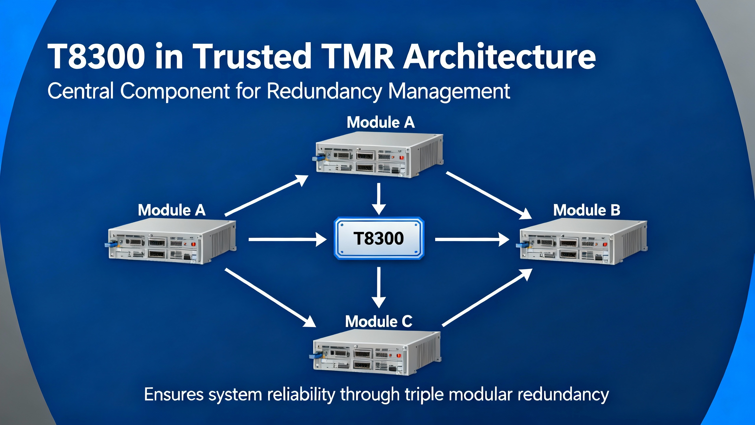
ICS Triplex Trusted is a highŌĆæintegrity safety PLC platform built around Triple Modular Redundancy. Three independent processing channels execute the same logic in parallel, with voting and integrity checks so the system can tolerate a fault in one channel while remaining in a safe state. According to explanations from NewGenPLC, this Trusted TMR architecture is widely used in oil and gas, nuclear, and chemical processing where fault tolerance, diagnostics, and deterministic behavior matter.
Within this platform, the T8300 expander chassis belongs to the Trusted hardware family supplied by Rockwell Automation. The expander chassis is not a CPU in its own right; it is a mechanical and electrical frame that carries Trusted Expander Processors and highŌĆæintegrity T84xx I/O modules. The NewGenPLC overview of the Trusted system notes that components such as the T8311 Expander Interface and T83xx hardware are what allow Trusted systems to scale across large plants by adding distributed I/O while keeping safety logic in a TMR controller such as the T8100.
In other words, a T8300 expander chassis is what you use when the main Trusted rack no longer has enough I/O capacity or when you want to push I/O closer to the field while still staying inside the Trusted safety architecture.
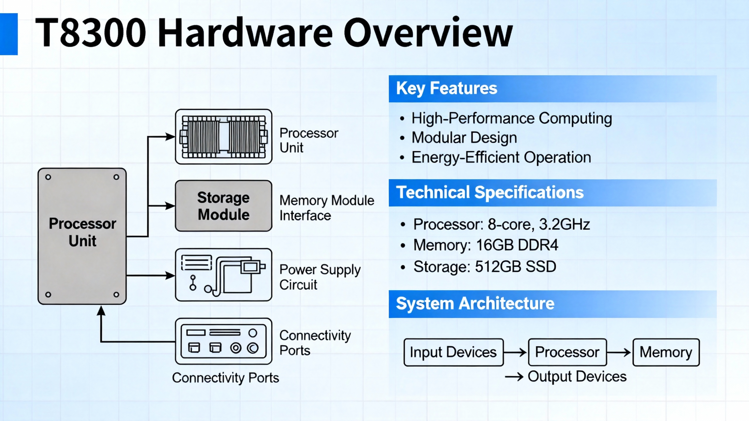
Rockwell AutomationŌĆÖs user documentation and republished manuals describe the T8300 as part of the Trusted system, providing both mechanical support and the internal backplane that carries power and communications. The key physical and functional characteristics are summarized below.
| Aspect | Description (per Rockwell Automation T8300 documentation) |
|---|---|
| Role | Expander chassis providing housing and backplane for Trusted Expander Processors and highŌĆæintegrity T84xx I/O modules |
| Height | 6U, approximately 10.5 in |
| Mounting | Designed for 19 in fixed or swing frames, or rear (panel) mounting in a suitable enclosure |
| Module capacity | Two dedicated Expander Processor slots on the left, plus up to twelve highŌĆæintegrity I/O slots, for a total of up to fourteen modules |
| Backplane | Integrated power distribution and triplicated InterŌĆæModule Bus connectors to all slots |
| Module connectors | DIN 41612 connectors in 32ŌĆæ, 48ŌĆæ, 64ŌĆæ, and 96ŌĆæway variants to support different I/O densities |
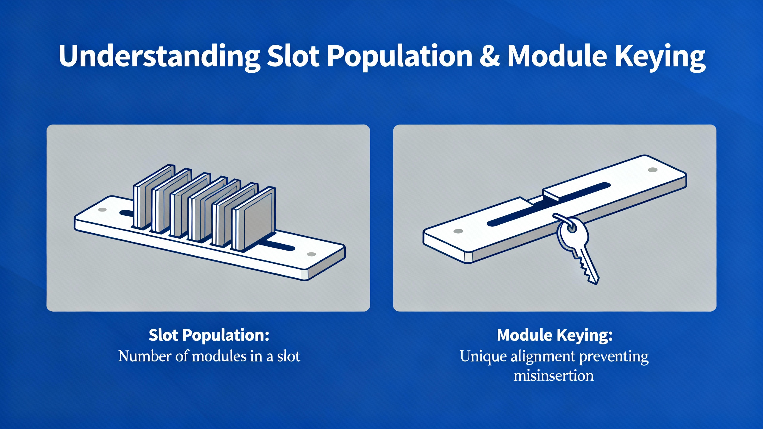
| Slot keying | Mechanical keying so only the correct module types can be inserted into each slot |
| Configuration switch | Triplicated fourŌĆæposition DIP switch on the backplane used to set system or chassis identification |
| Power input | FourŌĆæpole connector on the backplate for nominal dual +24 V DC feeds from highŌĆæintegrity supplies |
The chassis is designed to be fed from a dual +24 V DC highŌĆæintegrity power supply, typically the Trusted power supply hardware. Manufacturer guidance emphasizes that the intent is to feed the chassis from dual highŌĆæintegrity sources and to populate it only with appropriately keyed Trusted modules, mounted in a 19 in rack or suitable electrical enclosure.
Understanding this hardware picture is essential before you decide where to put the chassis and what to load into it.
The most common configuration problems with Trusted expander chassis do not come from the screwdriver work. They come from poor planning of the topology, addressing, and power. Before ordering cable or reserving rack space, you should treat the T8300 like any other critical part of your safety architecture and work from the top down.
Experienced safety engineers such as William (Bill) Mostia Jr., writing on Control.com about mixed systems that include ICS Triplex hardware, consistently ask for a picture rather than a long email of text. The reason is simple. In a multiŌĆærack, multiŌĆæinterface safety system, a block diagram immediately shows how processors, expander interfaces, communication modules, and I/O racks relate to each other.
For a T8300 deployment, draw a simple block diagram that includes the main Trusted TMR controller, any T8311 or similar expander interfaces, each T8300 rack, its expander processors, and the I/O groups assigned to that rack. Include power sources for the T8300 as well. A oneŌĆæpage block diagram that everybody agrees on eliminates ambiguity about where each safety function lives.
After the highŌĆælevel architecture is clear, decide exactly what the T8300 chassis will carry. The expander chassis provides two slots for Trusted Expander Processors on the left and up to twelve highŌĆæintegrity T84xx I/O modules. That is a generous amount of I/O, but it disappears quickly in real plants if you lump everything into one rack.
A pragmatic approach is to allocate chassis by function or by plant area. One chassis might be reserved primarily for shutdown valves and critical digital outputs using highŌĆæintegrity DO modules; another might handle analog inputs for a particular process unit. Grouping by function helps both when you write logic and when maintenance technicians are hunting a fault years later.
Pay attention to connector style and density. T8300 I/O positions support DIN 41612 connectors in 32ŌĆæ, 48ŌĆæ, 64ŌĆæ, and 96ŌĆæway formats. That flexibility lets you choose highŌĆædensity terminations for large DI or DO packs and lowerŌĆædensity connectors where heavy gauge or special signal wiring is needed. The choice of module and connector should appear explicitly in your I/O schedule and in the block diagram so there are no surprises for wiring teams.
The expander chassis is designed to be supplied from dual +24 V DC feeds, usually from a Trusted highŌĆæintegrity power supply. In a safety system context, the second feed is not a convenience; it is part of the fault tolerance strategy. If both feeds come from the same breaker or the same small power supply, you have preserved the appearance of redundancy while losing the benefit.
Early in the design, calculate the worstŌĆæcase current draw for the modules you intend to install, using each moduleŌĆÖs datasheet. Confirm that the highŌĆæintegrity power supply can support that load with margin on both feeds. Decide where each feed originates so that a failure in one panel or one DC distribution rail cannot bring down both supplies at once. Document this in your power and grounding drawings, not just in the logic design.
Once planning is complete, you can move to the mechanical installation. The T8300 chassis is six rack units high and roughly 10.5 in tall, intended for standard 19 in frames or for rear mounting inside an enclosure. That height matters if you are fitting multiple chassis in a single cabinet, especially where space must also be reserved for network switches, marshalling terminals, or HMI hardware.
During mounting, treat the chassis as you would any critical safety hardware. Fix it to a rigid 19 in frame or to a properly braced back panel so that vibration and cable load do not stress the backplane. Provide enough clearance above and below the chassis for airflow and for module removal without interfering with adjacent equipment. If your installation uses swing frames, verify that the fully cabled frame can still swing without straining any cables attached to the T8300.
The Trusted Maintenance Training Manual from ICS Triplex emphasizes that illustrations and figures in the documentation are intended to clarify the text, not to serve as turnkey engineering designs. That principle applies here. Use the manufacturerŌĆÖs mounting details to understand the footprint and fixing points, then design your cabinet so that the chassis and its cabling are protected, accessible, and consistent with local mechanical standards.
Before moving on to wiring, verify that the backplane area is clean, the card guides are unobstructed, and there is no metal swarf or debris in the enclosure. A small piece of debris across a backplane or connector can create exactly the intermittent faults that are hardest to debug later.

Power enters the T8300 expander chassis through a fourŌĆæpole connector on the backplate intended for dual +24 V DC feeds. The manufacturerŌĆÖs intent, as stated in documentation summarized by Rockwell Automation and resellers, is that the chassis is powered from dual highŌĆæintegrity supplies that provide redundant feeds.
In practice, that means you route two independent positive feeds and their returns from a Trusted highŌĆæintegrity power supply or another qualified source. Confirm polarity and terminal markings against the official manual and your panel schematic before landing any wires. It is good practice to clearly label each feed at both ends and to land them through appropriately sized protective devices in the DC distribution panel.
Grounding must follow both the manufacturerŌĆÖs recommendations and the plantŌĆÖs grounding philosophy. Typically, you will bond the enclosure and any chassis ground points solidly to the plant protective earth while managing signal reference grounds in a way that balances noise immunity and groundŌĆæloop control. The Trusted Maintenance Training Manual stresses that users are responsible for assessing suitability and safety of each application; that includes verifying that your grounding scheme works for your siteŌĆÖs EMC and safety requirements.
Before energizing, check that both DC supplies are healthy, correctly fused, and capable of starting under load. Bring up one feed at a time if your procedures permit, watching for any unexpected current draw or alarms, then enable the second feed. The point is to verify that a singleŌĆæfeed failure does not drop the chassis.

The T8300 backplane is where power and the triplicated InterŌĆæModule Bus are distributed to every module position. The physical slot arrangement is fixed by design. The two leftŌĆæhand slots are reserved for Trusted Expander Processors; up to twelve additional slots to the right are for highŌĆæintegrity T84xx I/O modules, with a total of up to fourteen modules per chassis.
Each module plugs directly into the backplane and connects to the triplicated bus through its rear connector. The chassis supports both single and double connector options depending on module type. Critically, the slots are mechanically keyed so that only the correct module type can be inserted into a particular slot. This is not just a convenience feature; it is a safety mechanism that reduces the risk of misŌĆæinserting a module with incompatible voltage ratings or signal characteristics.
When loading modules, always crossŌĆæcheck the planned slot allocation in your drawings against the part numbers physically in your hand. Ensure that the mechanical keying matches, and never force a module that does not seat smoothly. ICS TriplexŌĆÖs AADvance Build Manual, covering a related but different product line, illustrates the importance of mechanical keying by describing coding pegs that prevent mismatched termination assemblies. The Trusted expander chassis achieves the same underlying goal: it should not be physically possible to install the wrong module in a keyed slot if the keying is left intact.
Once all modules are inserted, inspect that every module is fully home in its guides, that retaining screws or levers are secure as specified, and that field connector access is clear for the wiring teams.
On the T8300 backplane there is a fourŌĆæposition DIP switch that the Rockwell Automation documentation describes as triplicated for highŌĆæintegrity operation. This switch is used to set a system or chassis identification value so that the Trusted logic solver and diagnostic tools can distinguish one expander chassis from another.
The exact bitŌĆætoŌĆæfunction mapping of this DIP switch is defined in the official T8300 and system configuration manuals, and you must follow those documents for the precise encoding. From a configuration perspective, there are several practical considerations that matter on site.
The first consideration is to define a simple, consistent addressing scheme across all T8300 racks in the installation before you touch the hardware. Many teams choose to number expander chassis in a leftŌĆætoŌĆæright or topŌĆætoŌĆæbottom order in the cabinet, then carry that numbering into the engineering database and the DIP settings. Whatever scheme you adopt, document it in your causeŌĆæandŌĆæeffect charts and wiring schedules.
The second consideration is to treat the DIP switch position as a controlled configuration item. Use a nonŌĆæconductive tool to set the switches, record the final setting in your asŌĆæbuilt drawings, and label the chassis externally with its identity. If the DIP setting and the configuration in the Trusted controller disagree, the chassis will not behave as intended and may be reported by the systemŌĆÖs diagnostics. In the worst case, I/O that you believe is active may not be associated with the right safety logic.
Finally, remember that the DIP switch is part of the TMR integrity of the system. The hardware implements it in a way that aligns with the triplicated architecture, so from the installerŌĆÖs point of view you configure it like any other fourŌĆæposition DIP and allow the Trusted platform to take care of reading it redundantly.
A T8300 chassis does not live in isolation; it is part of a networked Trusted safety system. As discussed in the NewGenPLC description of the Trusted TMR system, modules such as the T8311 Expander Interface and various communication modules provide highŌĆæspeed, faultŌĆætolerant networking between racks and subsystems. That is how an expander chassis, sitting out near the process unit, participates in the same safety functions as the main controller rack.
At the logical level, the Trusted configuration associates each expander processor and its I/O modules with specific tasks and safety functions. The T8300 simply provides the slots and backplane for those modules. At the physical level, you need to ensure that the expander processors in the T8300 are correctly cabled into the expander interfaces or communication modules in the main rack, that the network topology follows Rockwell AutomationŌĆÖs design guidance, and that channel redundancy is preserved endŌĆætoŌĆæend.
In a large plant spread over hundreds of yards, the benefit of this distributed architecture is substantial. You can mount a T8300 chassis closer to field devices, reducing cable lengths and voltage drop, while still keeping all safety logic inside the Trusted TMR controller. The expander chassis becomes a remote extension of the same highŌĆæintegrity safety domain.
Commissioning is where configuration mistakes show up. The goal is to catch them in a controlled test, not after startup. A structured approach built around what the manuals and field practice recommend will save time and rework.
Before applying power, walk the installation with the full set of drawings. Confirm that the chassis is mounted as designed, that the expander processors and I/O modules match the slot plan, and that the I/O connector types and keying align with the wiring harnesses and termination assemblies provided. Verify that both +24 V DC feeds are landed on the correct power connector poles and that labeling matches the power and I/O diagrams.
On first powerŌĆæup, bring up the Trusted system in a controlled environment such as a factory acceptance or site acceptance test. Watch the expander processors and modules in the T8300 for their powerŌĆæup states and diagnostics. The Trusted platform is known, from vendor literature, for its diagnostic transparency and realŌĆætime fault reporting across its modules. Use those diagnostics intentionally: check that each I/O module in the T8300 reports as present, that there are no unexpected configuration or communication faults, and that the chassis identity derived from the DIP switch matches what the controller configuration expects.
After the hardware and configuration health look correct, conduct pointŌĆætoŌĆæpoint I/O checks. Stimulate each input channel at the field terminal and observe that the correct Trusted I/O point changes state in the engineering workstation or test HMI. For outputs, use simulated loads where possible to verify that the correct devices actuate under test commands and that redundant outputs behave as designed. This is the stage where mistakes in I/O allocation, wiring to the wrong DIN 41612 connector, or misŌĆædocumented channels are most easily found and corrected.
Throughout commissioning, keep in mind the disclaimers from the Trusted Maintenance Training Manual. ICS Triplex explicitly states that no manual can cover all hardware variations or every installation and maintenance contingency, and that users are responsible for determining suitability and safety. Use the manuals as authoritative references, but apply engineering judgment and local standards for the specifics of testing and acceptance.

In real installations, the same classes of problems repeat themselves around expander chassis, regardless of the plant or integrator. Many of them are avoidable with a little discipline.
One frequent issue is treating the dual +24 V DC feeds as optional. The T8300 chassis is intended to be powered from dual highŌĆæintegrity supplies. When teams tie both feeds back to a single small supply or breaker, they remove a layer of protection without realizing it. Reviewing the power oneŌĆæline with the same rigor as the logic diagrams helps avoid this trap.
Another common problem is ignoring mechanical keying. Trusted T84xx I/O modules and the T8300 slots are keyed so that incompatible modules should not fit. If installers defeat keying or mix modules that are not in the design, the system may power up but exhibit subtle failures, such as incorrect field voltage ratings or unexpected diagnostics. Adhering strictly to module keying and partŌĆænumber checks prevents these errors.
A third pattern is poor documentation of DIP switch settings and chassis identities. When the system is new, everybody remembers how the racks are numbered. After a few years and a few plant turnarounds, that memory fades. Writing the chassis ID on the front, recording the DIP setting in the asŌĆæbuilt documentation, and updating the block diagram when a chassis is added or repurposed are simple steps that preserve clarity.
Finally, technicians sometimes assume that every example wiring or layout figure in the documentation is a recommended design. ICS TriplexŌĆÖs own documents state that figures and tables are provided to illustrate concepts, not to serve as final engineering solutions. Taking shortcut designs from examples without checking against your own safety requirements, national codes, and company standards is an invitation to trouble.

The following table consolidates the most configurationŌĆærelevant aspects of the T8300 expander chassis for dayŌĆætoŌĆæday use. It is not a substitute for the official manual, but it helps as a mental checklist.
| Configuration item | Practical notes |
|---|---|
| Chassis role | Expands a Trusted safety system by hosting Expander Processors and highŌĆæintegrity T84xx I/O modules |
| Module slots | Two Expander Processor slots (left side), up to twelve I/O module slots to the right |
| Backplane architecture | Triplicated InterŌĆæModule Bus and common power distribution to all module slots |
| Connectors | DIN 41612 field connectors in multiple pin counts to match different I/O densities |
| Power feeds | Dual +24 V DC, fourŌĆæpole input; intended to be supplied from highŌĆæintegrity dual power supplies |
| Identity configuration | FourŌĆæposition, triplicated DIP switch on backplane sets chassis or system identification |
| Mechanical protection | Slot keying prevents incorrect module type insertion; chassis intended for 19 in rack or panel mounting |
Use this table alongside your own projectŌĆæspecific checklists to keep configuration consistent across the lifecycle of the system.
According to Rockwell Automation documentation summarized in independent manuals, a T8300 expander chassis provides two dedicated slots for Trusted Expander Processors and up to twelve slots for highŌĆæintegrity T84xx I/O modules, for a total of up to fourteen modules in one chassis.
The T8300 expander chassis is designed as part of the Trusted system to house Trusted Expander Processors together with highŌĆæintegrity T84xx I/O modules. For any other module families or special function modules, you should consult the official Rockwell Automation hardware guides to confirm compatibility.
The expander chassis power input is specifically described as a nominal dual +24 V DC feed from highŌĆæintegrity supplies. That reflects the safety philosophy of ICS Triplex Trusted systems, which is to build redundancy into every layer. Running from a single supply undermines that intent and should only be done if the official documentation confirms that it is permissible for your safety requirements and your risk assessment agrees.
The backplane includes a fourŌĆæposition DIP switch that the documentation describes as triplicated to support a robust chassis identification scheme within the Trusted TMR architecture. Triplication aligns this configuration information with the threeŌĆæchannel design of Trusted systems so that identification data is available with the same integrity as the rest of the system. As an installer, you simply set the DIP switch according to the manual; the hardware manages the redundant representation internally.
Even in smaller systems, practice from experienced safety engineers, including the Control.com discussion on Honeywell Safety Manager and ICS Triplex hardware, shows that a simple block diagram is invaluable. It clarifies how the T8300 chassis relates to the main TMR controller, the expander interfaces, and the plantŌĆÖs power and communication networks. That clarity reduces misconfiguration and makes it much easier to get effective technical help later.
Configuring a T8300 expander chassis is not just a matter of setting a few switches and sliding in cards. It is about extending a highŌĆæintegrity Trusted safety system in a way that preserves its redundancy, diagnostics, and maintainability. If you start with a clear block diagram, respect the power and keying rules the hardware is built around, and treat DIP settings and documentation as part of the safety lifecycle, the T8300 becomes a straightforward, dependable building block rather than a source of surprises during startup.


Copyright Notice © 2026 mooreautomated.com All rights reserved,Moore Automated is not an authorized distributor or representative of the manufacturers featured on this website. Brand names and trademarks featured are the property of their respective owners.


Leave Your Comment