


MP 3009X
Get A Quote
As an automation engineer who spends as much time in front of a rack door as at a desk, IŌĆÖve learned that diagnosing and replacing a Main Processor (MP) module in a Triconex safety system is as much about disciplined procedure as it is about recognizing the story the system is telling you. This guide lays out a pragmatic, field-proven approach to finding the true cause of an MP fault and changing a module without creating new problems, while staying within safety and compliance margins. It reflects the diagnostics capability of TriconexŌĆÖs triple modular redundant architecture, the practical realities of transient hardware faults, and the demands of the safety lifecycle established by the U.S. process industry.
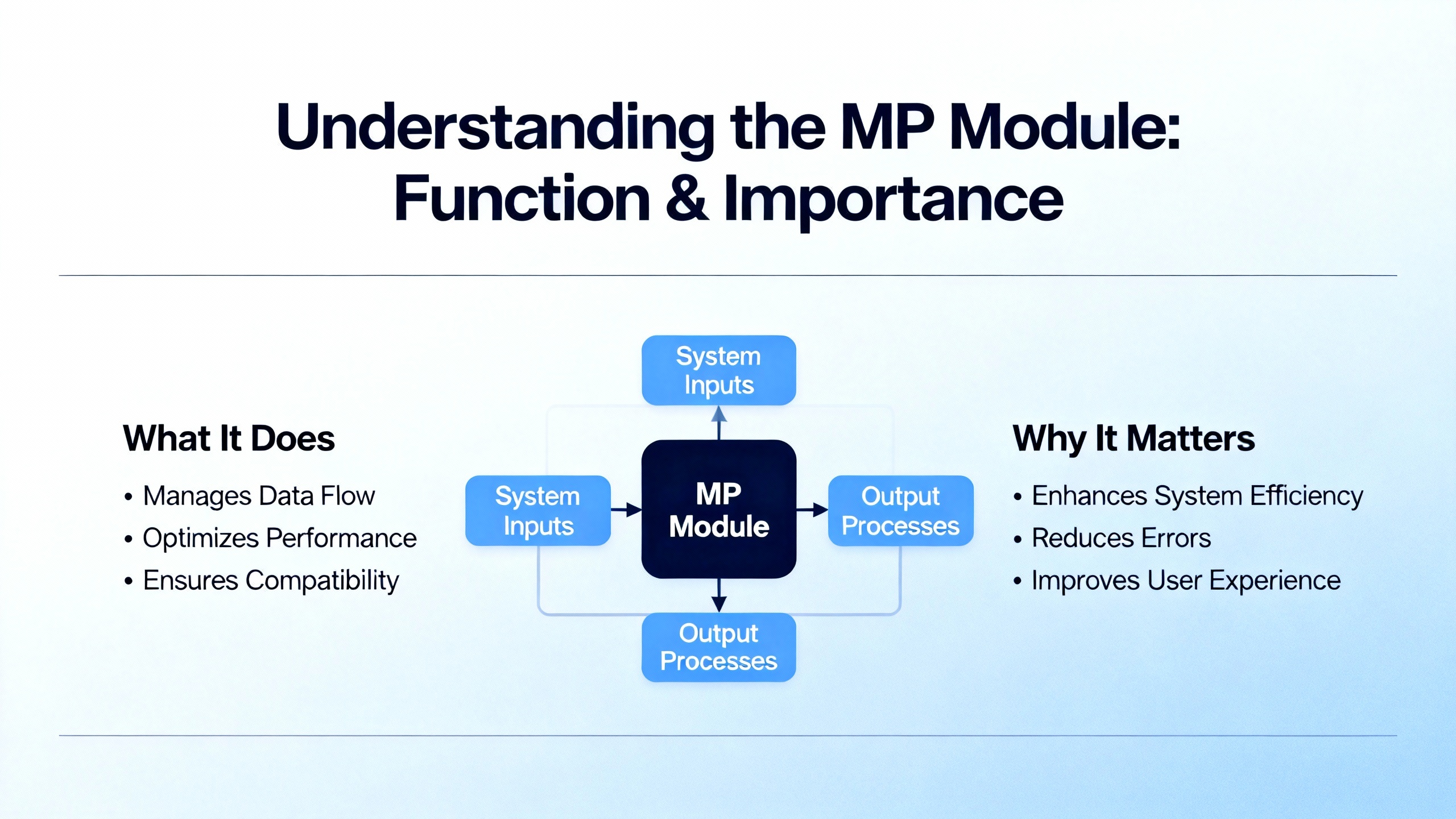
In a Triconex safety instrumented system, the MP module is one of three logic-solver legs in a Triple Modular Redundant (TMR) architecture. Each leg executes the safety application independently and in parallel; the system then votes inputs and outputs so a single fault cannot compromise a safety function. Digital inputs and outputs are voted; analog inputs are typically handled by a mid-value selection approach so that a single noisy or drifting leg cannot dominate the result. This approach is explained in vendor materials for the Triconex platform and is the cornerstone of its fault tolerance. Because each leg is isolated, a failure in one leg should be masked by the other two. That, in turn, allows repairs at the module level while the controller remains online, following published guidance that modules are keyed to prevent insertion into the wrong slot and designed for on-line replacement when procedures are followed. Schneider ElectricŌĆÖs Triconex program literature and general-purpose technical references emphasize this architecture and its goal: remain safe during a fault and remain available whenever possible.
In the plant, faults rarely arrive with a neat banner. On an analog card, a momentary failure can trigger a trip if the safety logic is designed to fail safe quickly, as a forum report from Control.com described. The poster noted a transient, self-clearing fault that nonetheless forced a shutdown. That single anecdote is enough to reinforce a familiar lesson for safety systems: they are designed to prefer shutdown over uncertainty. With MP modules, the symptoms can range from a single-leg FAULT indication and a degraded but running system, to an alarm storm that includes communication and power indicators, to a quiet fault that appears only as a diagnostic entry that a technician misses during busy shifts. What matters most early on is to trust the hardware diagnostic coverage that Triconex and independent qualification work have documented. A nuclear qualification FMEA submitted to the NRC via Kanterella explains that Tricon self-diagnostics are designed and validated to detect and alarm single internal module failures. That confidence lets you focus on corroborating what the front panel and the diagnostic tools already know.
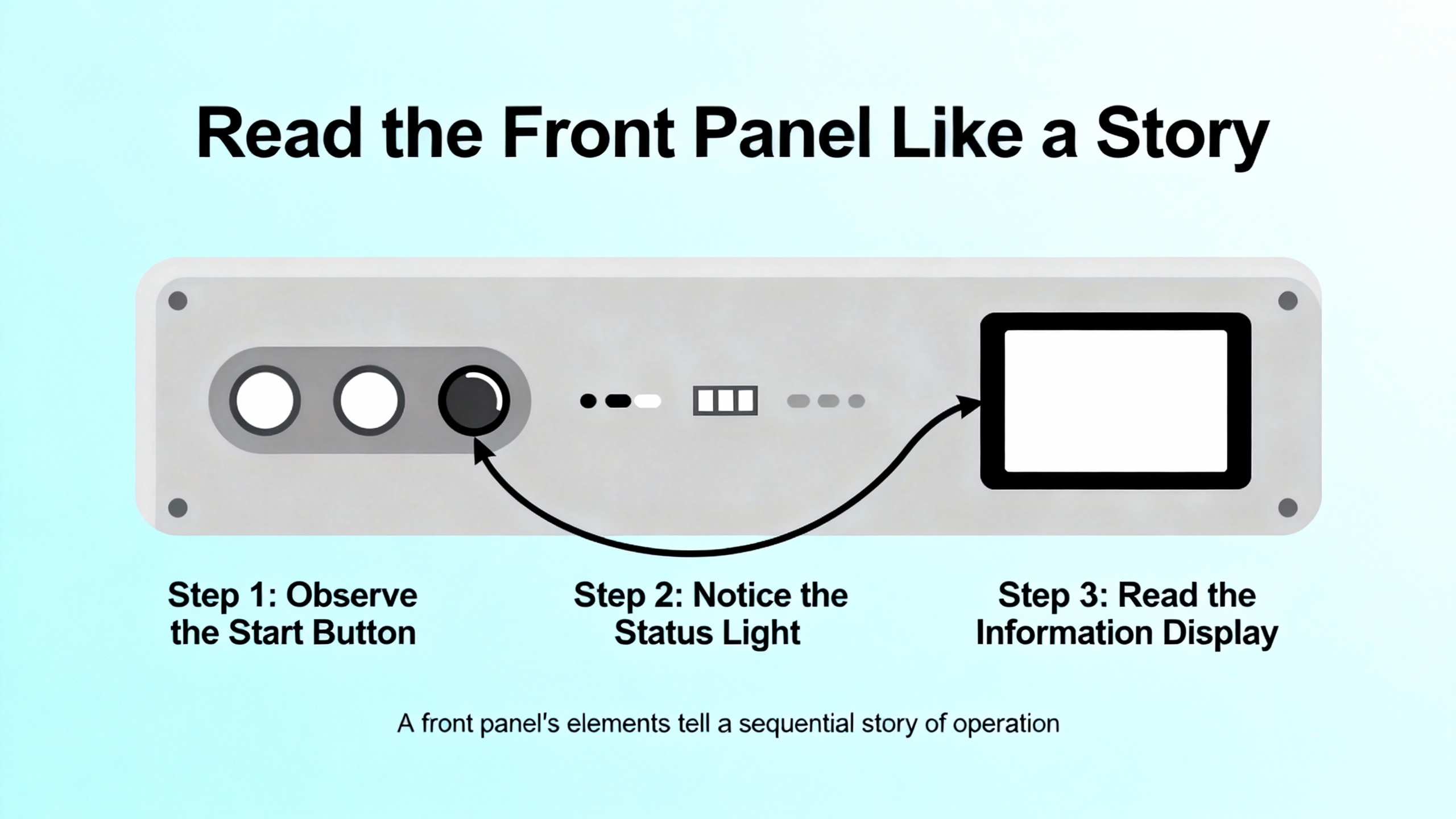
On the Trident MP 3101 family, which is representative of how Triconex presents status, the front panel groups indicators by function so you can assess health in seconds. The status group uses PASS, FAULT, and ACTIVE to signal basic module state. The mode group uses REMOTE, RUN, PROGRAM, and HALT to tell you whether the controller will accept remote commands, is executing the safety application, is in a configuration state, or is stopped. The alarm group gives fast context with FIELD POWER, LOGIC POWER, SYSTEM ALARM, PROGRAM ALARM, OVER TEMPERATURE, and LOCK. The communications area shows activity and link state across the IO BUS and the COMM BUS, along with SERIAL and TRISTATION activity and a LINK indicator. The intent is obvious: give a field tech a truthful and low-latency snapshot without having to open a laptop.
A condensed quick reference table helps with triage:
| Panel Area | Indicator | What it tells you at a glance | First checks to make |
|---|---|---|---|
| Status | PASS, FAULT, ACTIVE | Basic health and whether the leg is participating in execution | If PASS is off or FAULT is on, note whether other legs are PASS to confirm a single-leg condition |
| Mode | REMOTE, RUN, PROGRAM, HALT | Operating state and whether remote commands are permitted | Verify the key-switch and mode before attempting any configuration or stop/start action |
| Alarms | FIELD POWER, LOGIC POWER, SYSTEM ALARM, PROGRAM ALARM, OVER TEMPERATURE, LOCK | Power rails health, general system alarms, configuration alarms, thermal condition, and lock states | Correlate with power distribution and cabinet environmental status; confirm locks and access control |
| Communications | IO BUS TX/RX, COMM BUS TX/RX, SERIAL TX/RX, TRISTATION TX/RX, LINK | Backplane and external comms activity and link integrity | Check cabling, backplane seating, and whether comms loss is localized to one leg or system-wide |
This mapping aligns with the Trident MP front panel description in the Manualslib reference. It is vendor-agnostic enough to use across Triconex families for initial triage, with care taken to check the specific module and firmware documentation on site.
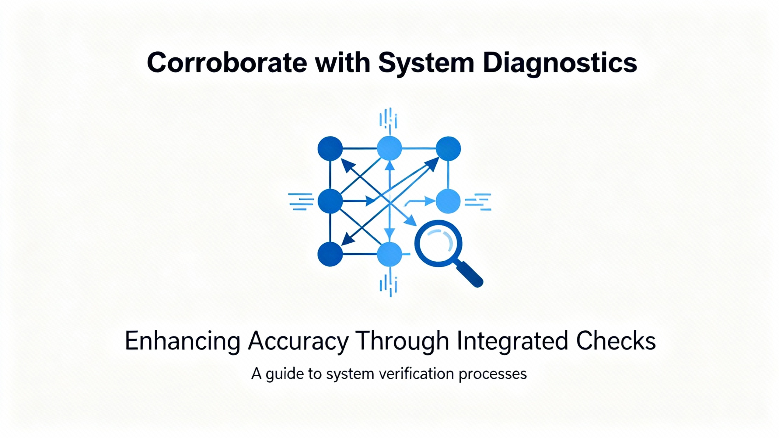
After the front-panel read, move to the controllerŌĆÖs diagnostics. TriStationŌĆÖs Diagnostic Panel and the controllerŌĆÖs event and system logs provide time-correlated entries for module faults, channel faults, and communication issues. The Enhanced Diagnostic Monitor user documentation underscores that diagnostics are first-class citizens in the ecosystem and that faults are stored in variables and logs for operators to review. Use those records to align the moment your FAULT indicator latched with any power sag, cabinet thermal excursion, or network flap recorded elsewhere. The nuclear FMEA analysis emphasizes that the platformŌĆÖs self-diagnostics cover single internal module failures, which means that when a module reports a fault, you should assume itŌĆÖs credible and look for coincide signals of power or environment to determine if it is a true hardware issue or a symptom of a more systemic problem.
The key-switch and operating mode matter for both diagnosis and replacement. The FMEA material explains that the TMR-ganged key-switch logic governs command categories and can inhibit a STOP from the TriStation engineering workstation when required. Before you expect a mode change to take effect or a download to proceed, confirm the physical key-switch position matches your intended action. That simple check avoids unnecessary downtime and confusing error cascades.
Not every MP fault is caused by the MP. The most effective field investigations follow a consistent set of pathways. Start with power quality because MP faults often correlate with dips, sags, or noisy supplies feeding either field wiring or the controllerŌĆÖs logic rails. The Control.com thread about an analog card failure called out sagging supplies and noisy power as prime suspects; the same culprits can destabilize an MP long enough to register a FAULT.
Move to wiring and terminations, not only on the MPŌĆÖs backplane seating but also on termination panels and external connections. Loose terminals and intermittent shorts can create ground loops or EMI coupling paths that mimic or cause module failures, and those symptoms can be transient. Once power and wiring are ruled out, confirm environmental limits. Triconex publishes operating ranges that expect good cabinet ventilation, managed humidity, low dust, and controlled vibration. The Control.com discussion advised exactly that: check cabinet ventilation, dust, corrosion, and vibration against specifications. Over-temperature alarms on the MP panel give you the quickest clue if cabinet airflow is part of the problem.
Finally, review redundancy and configuration. The point of TMR is to ride through a single fault; if a single module issue forced a total shutdown unexpectedly, then either the configuration demanded that behavior for safety reasons or the redundancy settings and voting logic need a fresh look. Vendor product information emphasizes a 2-out-of-3 voting strategy for safety and availability. If your safety case requires a trip on a single-leg diagnostic, document that and communicate it to operations so that it doesnŌĆÖt get misinterpreted as an availability defect. If not, evaluate whether configuration drift or an unintended test mode is undermining the redundancy you paid for.
It helps to pair symptoms with the most probable system boundary. When only one leg shows FAULT while the other two show PASS and the application remains in RUN, the odds favor a single module issue localized to that leg, such as a component failure or a seating issue. When multiple legs or multiple module types simultaneously report FAULT or power alarms, widen quickly to shared resources such as backplane power rails, cabinet power supplies, or environmental factors. If the MP shows clean PASS but you see pervasive I/O channel faults on multiple cards, do not replace the MP yet; focus on field wiring, termination panels, and the analog input modules themselves, particularly on platforms like the Triconex 3700 series where per-channel diagnostics indicate a channel fault but do not imply a module failure and where a module can continue to operate with channel-level failures while alerting via a Fault LED. Vendor instructions for the 3700 family spell out those distinctions, which can prevent unnecessary processor swaps.
When communications indicators are quiet or stuck on error for a single leg while the other legs are active, check backplane connectivity and module seating first. If the IO BUS or COMM BUS indicators are quiet across all legs, investigate a chassis-wide issue before you target one MP.
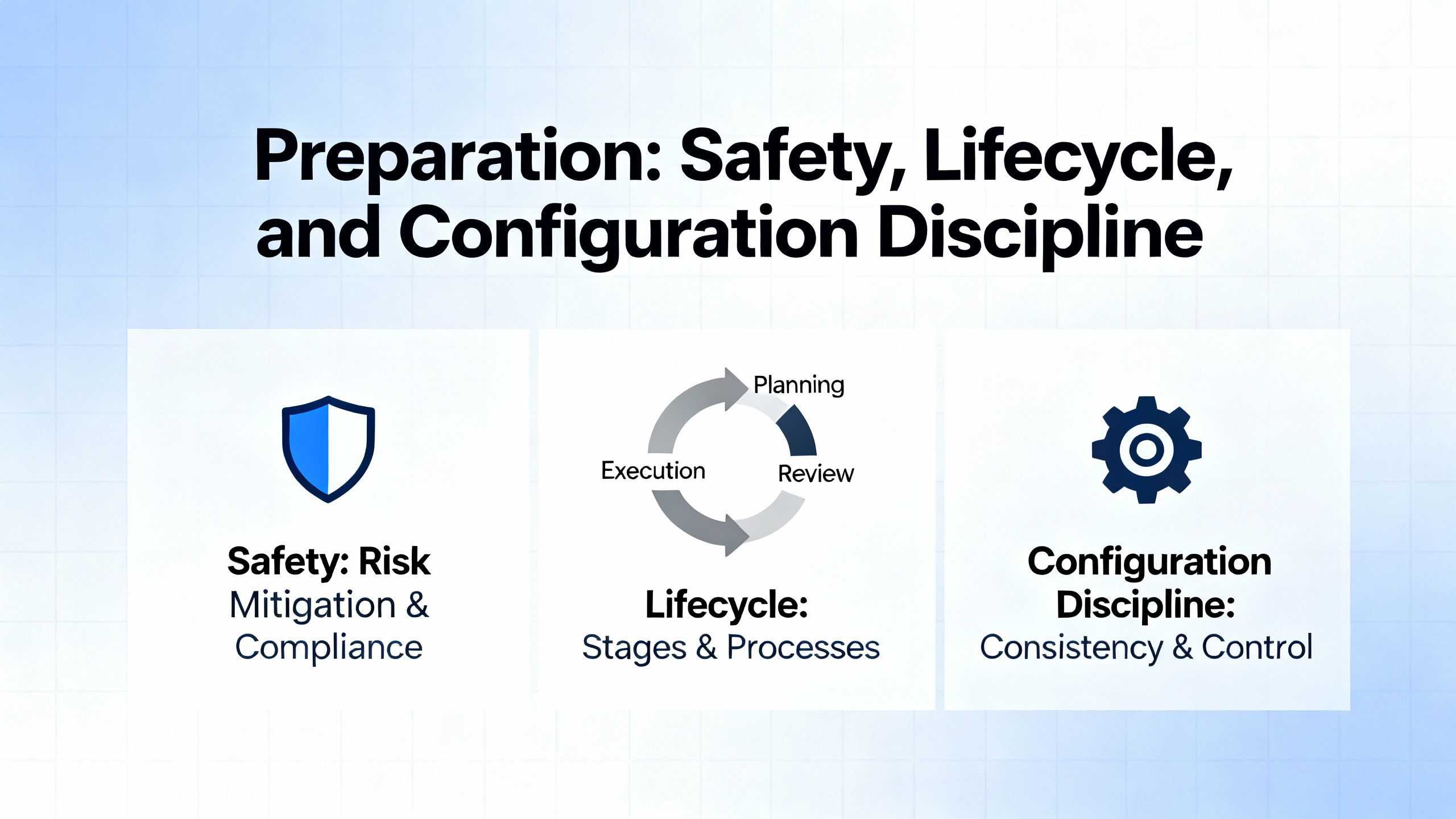
Before touching hardware, align your work with the Safety Instrumented System lifecycle practices defined by ISAŌĆÖs S84.01 standard. That means you should be executing against a Safety Requirements Specification and within management-of-change controls that protect your hazard studyŌĆÖs assumptions. Vendor references for Triconex stress independence of the safety system from the basic process control system, so ensure network boundaries and access controls remain in place during service.
Collect complete diagnostics and make a snapshot of controller state. Use TriStation to archive the current application, review the Diagnostic Panel for fault codes and timestamps, and check alarm history on the operator side of the house if a TCMI or other interface module is bridging to a DCS. Confirm you have an MP spare staged with the correct model and mechanical keying. Triconex modules are mechanically keyed to prevent insertion into the wrong slot, a useful safeguard when pressure is high. Check the spareŌĆÖs firmware and ensure it matches your installed baseline. Control.com contributors recommend maintaining spares with consistent firmware and using error-rate or age-based replacement policies; that discipline avoids introducing incompatibilities when you are already in a degraded state.
Begin by stabilizing the plant. Ensure the process is at a safe operating point to tolerate a temporary degraded state if you remove one leg. Confirm that at least two legs are showing PASS and that the system is executing in RUN. If the system is already down on a trip, coordinate with operations so that replacement is part of the restoration plan. Verify the controllerŌĆÖs key-switch and mode indicators. If a configuration or program transfer is required as part of your replacement sequence, the PROGRAM indicator and key-switch position must align with your procedure; the FMEA material notes that key-switch logic can inhibit STOP commands from TriStation under certain positions, so your expectations should match physical reality.
Next, document the current fault scene. Take dated photographs of the MP panel, capture TriStation diagnostics, and flag any FIELD POWER or LOGIC POWER alarms so you have a baseline if the replacement does not clear the symptom. Check cabinet temperature if the OVER TEMPERATURE indicator is active or if the cabinet feels hot to the touch.
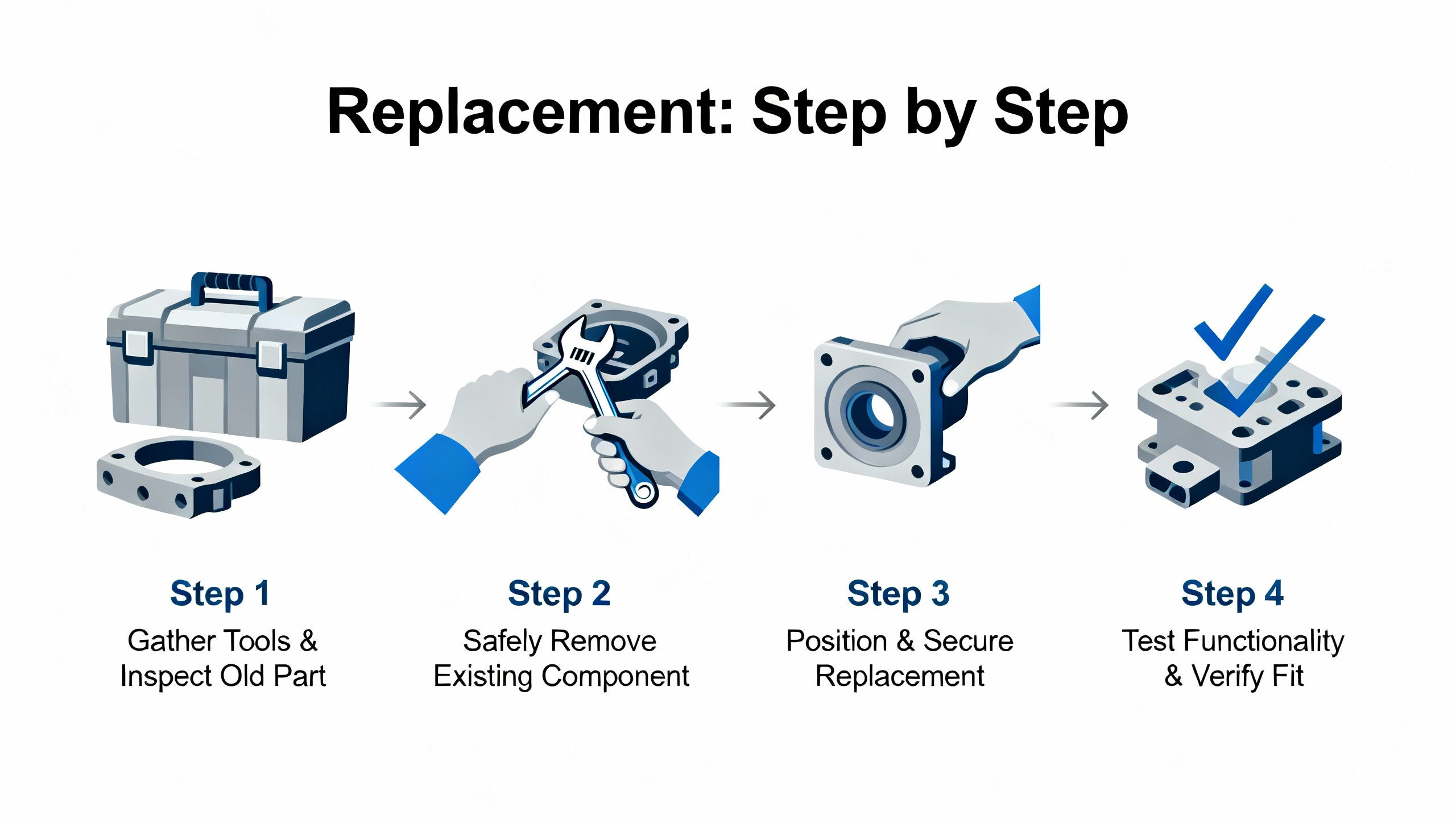
Then, remove the failed legŌĆÖs MP. Use antistatic precautions and follow the chassis instructions to disengage the module. Because Triconex is built to allow module-level maintenance without process interruption, removal of a single MP leg should not stop the system, but your plant procedures and the controllerŌĆÖs current state always take precedence. Seat the replacement MP firmly and confirm the backplane connector mates fully; mechanical keying prevents incorrect slot insertion, but incomplete seating is still a common trap.
After the new MP powers, watch the front panel closely. You should see the module go through its own self-test and begin to report PASS if conditions are favorable. Communications indicators on the IO BUS and COMM BUS should show activity, and the ACTIVE indicator should reflect that the module is participating. If a firmware or application download is part of your plantŌĆÖs procedure for MP replacement, execute that from TriStation once the key-switch and mode allow it. Remain patient during synchronization; do not rush mode changes or restarts. The nuclear FMEA documentation discusses timing analysis for scan and communication but, more importantly here, it reminds us that diagnostics and command categories are bounded by safety logic and key-switch positions. Align your actions with those constraints.
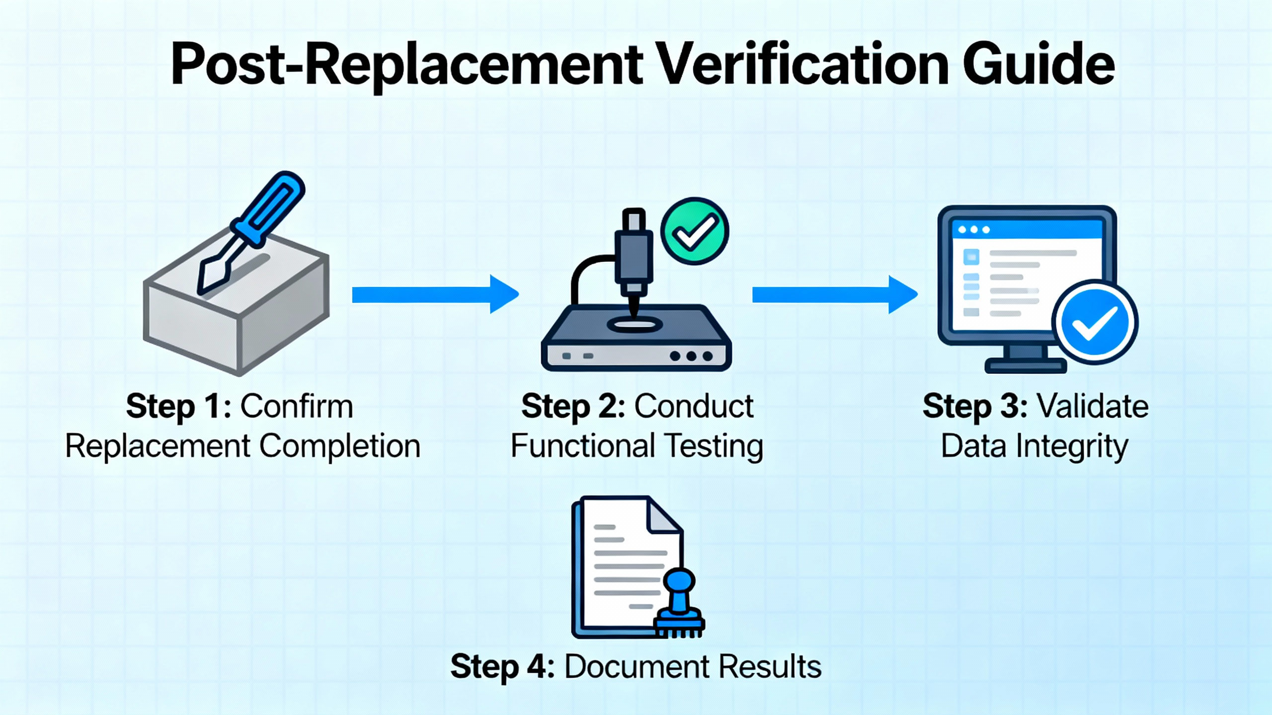
Finally, verify full TMR operation. One by one, confirm PASS across all three legs, check that the application is in RUN, and confirm that alarms cleared. Review logs to ensure the fault condition is resolved rather than suppressed. If the original symptom involved broader alarms, such as LOGIC POWER or cabinet over-temperature, track those to closure before declaring victory, because replacing an MP without addressing upstream causes guarantees a repeat.
Do not stop at green lights. Open TriStationŌĆÖs Diagnostic Panel again and print the event list around the time of the replacement; store that with your work order or maintenance record. Observe the controller for a reasonable soaking period. If possible, apply a functional test stimulus in coordination with operations, such as a nonintrusive proof test that reads, but does not trip, based on simulated conditions. While the 30ŌĆæmonth proof-test intervals cited in Triconex FMEA material apply to specific input and output conditions rather than MP modules, the principle is the same: verify that safety functions are alive and that diagnostics will speak up again if something slips.
One repair is never the end of the story. Clean up the root causes before they surprise you again. If power quality was implicated, instrument the supply with a recorder to catch sags or noise bursts during startups and heavy loads, and consider line conditioning or separate supplies for field and logic power. If ambient temperature is routinely high, improve cabinet ventilation and clean filters. If dust or corrosion are present, improve cabinet sealing and housekeeping. If EMI is suspected, review cable routing, shielding, and grounding. The Control.com threadŌĆÖs recommendations match what seasoned technicians actually find in the field: loose terminals, ground loops, and environmental stress cause intermittent failures that diagnostics truthfully capture but cannot correct on their own.
Also, strengthen your redundancy posture. Confirm that TMR and voting configurations still match your safety case, and review any overrides or bypasses that crept in during prior maintenance. Maintain tested spares and keep their firmware aligned with your installed baseline so a swap does not become a surprise upgrade. Consider a proactive replacement policy based on age, duty cycle, or error rates logged by diagnostics. The value is not only in preventing outages; it is in avoiding urgent work when the plant is least able to tolerate it.
Treat an MP spare like a precision instrument. Choose the exact model designated for your system, such as a Trident 3101 MP where applicable, and confirm chassis compatibility and mechanical keying. Verify firmware alignment with your fleet before it goes on the shelf and again before it goes into the rack. Store it in a controlled environment away from dust and moisture, and keep an acceptance test log. Perform a short install-and-sync test during a planned window on a development or test chassis if your site permits it, then reseal the module. Keep documentation with the spare, including a copy of the current application checksum and instructions for your siteŌĆÖs MP replacement sequence. These are humble steps, but they avoid late-night hunts for firmware and procedure owners.

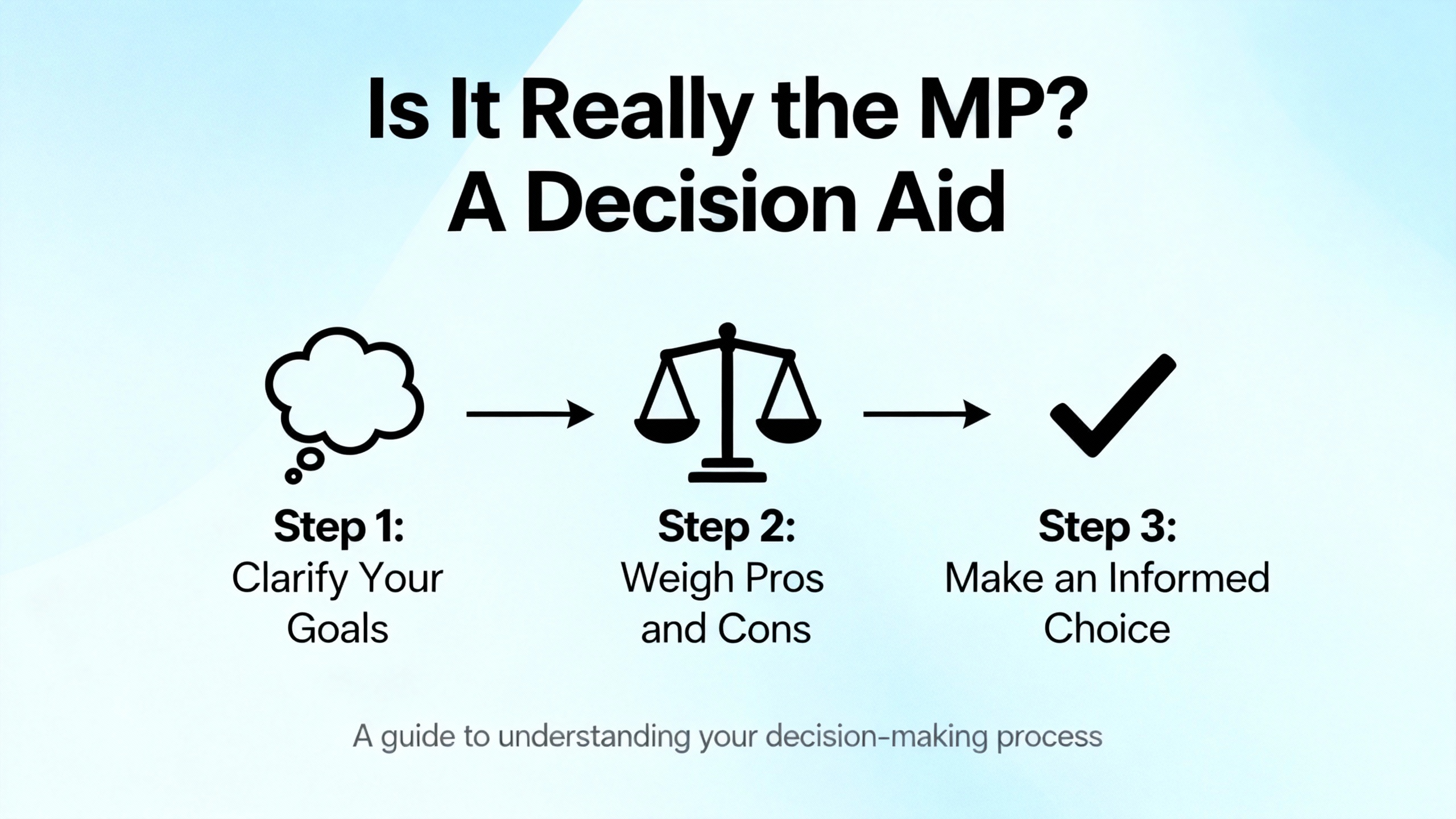
Triconex is engineered for on-line module replacement, and in many cases that is the right choice. The strongest advantage is clear: you maintain availability of safety functions and the process while addressing a single-leg fault, which is precisely the value proposition of TMR. There are tradeoffs. On-line work requires precise coordination and tight adherence to access control because a mode mistake or an unintended stop command can escalate quickly. It also locks you into the existing application baseline, which might preclude firmware or logic upgrades that would be desirable if you had an outage window. In contrast, a planned outage allows richer testing and broader remediation, but at a cost in downtime. The right decision comes from your Safety Requirements Specification and your operating risk profile, not from habit.
What if PASS remains off after replacement while the other legs are healthy? Focus first on backplane seating, module keying, and LOGIC POWER status. If those check out, review the Diagnostic Panel for specific fault codes and confirm firmware alignment with your siteŌĆÖs baseline before suspecting a second bad module.
Can an MP module be changed without stopping the process? The platform is expressly designed for module-level repair while online in a TMR configuration, as the vendorŌĆÖs architectural descriptions state. Your site procedures, risk assessment, and the systemŌĆÖs current state determine whether it is permitted in your case.
How do I ensure a transient MP fault doesnŌĆÖt trigger a total shutdown? That answer lives in your voting configuration and safety case. Vendor sources emphasize that TMR exists to sustain safe operation through a single fault, but if your logic is configured to trip on a single-leg diagnostic for safety reasons, the shutdown is correct. Review those settings if plant availability goals have changed.
TriconexŌĆÖs TMR design and module-level service approach are described in vendor platform overviews and in the Trident MP 3101 front-panel manual hosted by Manualslib. The triple-voter analog input behavior and per-channel diagnostics are explained in the 3700 Series analog input instructions maintained by Manuals Plus. Real-world transient failures that drive fail-safe trips are documented in user experiences on Control.com, which also list practical diagnostic steps ranging from power quality to environmental checks. The U.S. nuclear sectorŌĆÖs FMEA for Triconex, available through KanterellaŌĆÖs repository, outlines diagnostic coverage, key-switch command logic, and proof-testing practices, demonstrating an independently reviewed safety case. The SIS lifecycle framework, including the Safety Requirements Specification and integrity targets, is defined in ISA S84.01, which the industry aligns with for consistent, auditable practice. Schneider ElectricŌĆÖs Triconex Safety Systems pages summarize the TMR architecture and safety certifications in language that reinforces the platformŌĆÖs intent to stay available while being safe.
In the field, good troubleshooting is about being methodical and humble. Trust what the diagnostics tell you, prove what the environment can hide, and replace only what you have proved is at fault. When you do swap an MP, do it like a surgeon: prepared, deliberate, and patient. That mindset is how systems stay safe and plants keep running.


Copyright Notice © 2026 mooreautomated.com All rights reserved,Moore Automated is not an authorized distributor or representative of the manufacturers featured on this website. Brand names and trademarks featured are the property of their respective owners.


Leave Your Comment