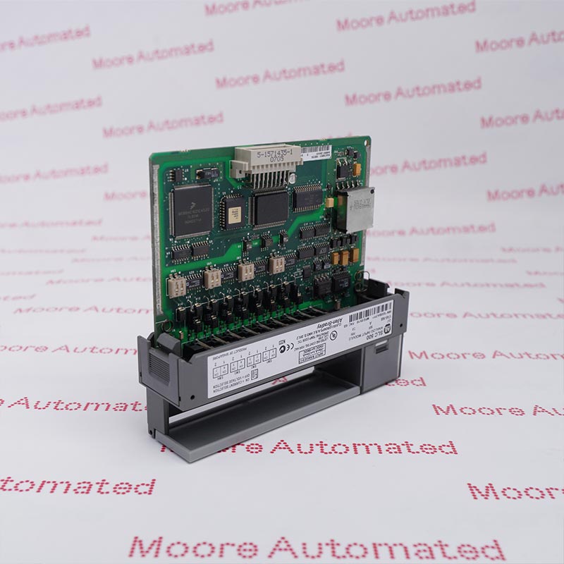
The Analog Input module can be installed in an I/O
rack, a Model 60 CPU rack, or a Series Six Plus CPU
rack. Before installing the Analog Input module, the
dual-in-line-package (DIP) switches immediately
behind the card slot on the rack backplane should be
set to reserve a group of 32 consecutive bits in the
appropriate Input Status Table of the CPU. For spe-
cific DIP switch settings, see below.
What is the architectural role and system-level function of IC600BF841 within the GE Series Six programmable control ecosystem?
The IC600BF841 functions as a high-density discrete input module within the GE Series Six PLC platform, serving as a critical interface between field-level digital signals and the central processing unit. It translates external 24V DC logic states into backplane-compatible data signals for deterministic control execution.
How does IC600BF841 implement its input acquisition methodology, and what signal conditioning mechanisms are embedded within its design?
The IC600BF841 utilizes opto-isolated input circuitry to condition and stabilize incoming field signals. This architecture ensures noise immunity, voltage threshold discrimination, and suppression of transient spikes, thereby maintaining signal integrity in electrically harsh industrial environments.
What electrical characteristics define the input sensitivity and threshold behavior of IC600BF841 under nominal operating conditions?
The IC600BF841 is engineered with defined ON/OFF voltage thresholds optimized for 24V DC logic systems. Its input impedance and current-limiting design ensure minimal loading on field devices while maintaining precise state recognition across varying supply tolerances.
In what manner does IC600BF841 achieve galvanic isolation, and how does this enhance system robustness against electromagnetic disturbances?
The IC600BF841 incorporates opto-electronic isolation between field inputs and backplane circuitry. This galvanic separation significantly mitigates ground loop effects, common-mode noise propagation, and electromagnetic interference, thereby enhancing overall system reliability and EMC compliance.
What diagnostic visibility and channel status indication mechanisms are integrated into IC600BF841 for real-time operational assessment?
The IC600BF841 provides per-channel LED status indicators, enabling immediate visualization of input state transitions. This facilitates rapid fault isolation, wiring verification, and supports maintenance-level diagnostics without requiring software-based interrogation.
How does IC600BF841 perform under high-noise industrial environments, and what design principles ensure signal fidelity?
The IC600BF841 is designed with multi-stage filtering, debounce circuitry, and optical isolation, allowing it to maintain signal integrity in environments characterized by high electromagnetic interference, motor switching noise, and voltage transients.
What backplane communication protocol and data mapping structure does IC600BF841 utilize within the Series Six architecture?
The IC600BF841 communicates via the proprietary GE Series Six backplane bus, where input states are mapped into predefined memory registers. This deterministic data mapping enables seamless integration into ladder logic and sequential control routines.
For more information on how your data is processed and stored by Moore automated please read our privacy policy.
Trusted by 5,000+ plants worldwide | Backed by our vast inventory of top-tier control parts, drives and servo motors, fast shipments are dispatched to cover your urgent needs. ABOUT US >>
Moore Disclaimer: Moore Automated's sales automation equipment and related solutions are intended for industrial automation and business operational efficiency improvement purposes only. Product information, technical parameters, and application cases are for reference only and do not constitute an absolute guarantee of performance for any specific industry, scenario, or final application. Actual equipment performance may vary depending on factors such as the usage environment, system integration method, and maintenance conditions. Users should confirm compatibility and safety based on professional technical assessments. Moore Automated assumes no liability for any direct or indirect losses caused by improper use, modification, or failure to operate according to specifications, to the extent permitted by law.