
Registered Address: 32D Floor Guomao Building, No.388, Hubin South Road, Siming District, Xiamen,Fujian, China
ISO 9001:2015 Certified
Our quality management system covers sourcing,testing and dispatch
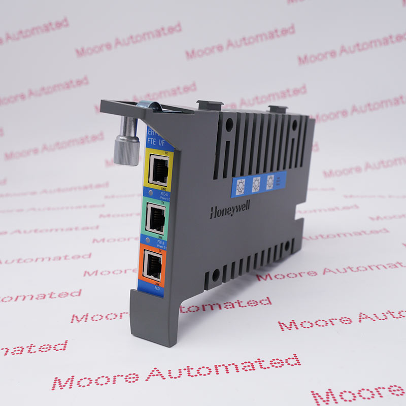
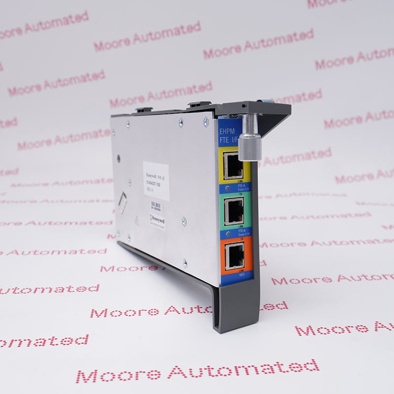
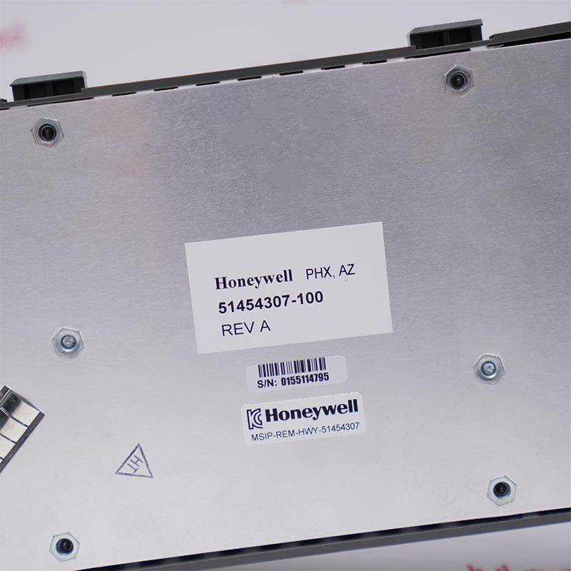
Honeywell 51454307-100 is the Enhanced High-Performance Process Manager Fault Tolerant Ethernet Interface module. The manufacturer service manual identifies three RJ45 Ethernet ports with LEDs, a backplane interface to the EHPM, 100 MHz operation and installation in the connector beneath the communications/control card. The same module is documented as applicable to EHPM and C300PM card files; network cabling, device index and hardware revision must be matched before replacement.
Honeywell identifies 51454307-100 as the Enhanced High-Performance FTE Interface module in the R690 HPM service manual and EUCN spare-parts list. The interface module has three RJ45 Ethernet ports with LEDs, communicates with the EHPM through the backplane, does not use the Global Bus and supports 100 MHz operation. Its power indicator is illuminated whenever 24 VDC from the cabinet power system is present, while transmit and link indicators report EUCN cable activity and link condition.
In an EHPM card file, the module mounts in the connector beneath the Enhanced High-Performance Communications/Control card in the first left-most slot. Honeywell's installation page also states that the FTE Interface module is applicable to both EHPM and C300PM. The parts list identifies FTE Cable A, FTE Cable B and a 100-Base-T crossover cable for FTE redundancy. Replacement therefore requires the complete part/revision, cable identity, device-index setting, card-file position and approved network topology to be preserved.
Record the complete 51454307-100 marking, printed revision, card-file location and FTE device-index setting before removal. Label all three RJ45 connections and capture their cable colors, switch destinations and redundancy role. A similar Ethernet interface or matching connector pattern does not establish compatibility with the installed EHPM or C300PM execution.
Verify whether the assembly is used in an EHPM or C300PM card file and follow the applicable Honeywell installation procedure. Inspect the connector beneath the communications/control card, observe ESD precautions and confirm the correct first-slot mounting relationship. Do not force the module or disturb adjacent backplane components.
After installation, restore the documented FTE A, FTE B and redundancy connections, then confirm power, transmit and link indicators. Verify the assigned device index, IP addressing, switch-port status, node visibility, alarms and redundant-path communication through authorized system diagnostics before returning the controller to process service.
The module provides three RJ45 Ethernet ports with LEDs and a backplane interface between the EHPM and its FTE connection. Honeywell documents 100 MHz operation and states that the module does not use the Global Bus. Preserve the FTE A and FTE B cable paths, redundancy connection, switch destinations, device-index setting and cabinet power context; do not assign field-I/O channel ratings to this network interface.
Photograph the complete marking, revision, rotary settings and all cable connections before removal, then follow the documented ESD and card-file installation procedure. After fitting the module, restore each labelled connection, confirm power/link/transmit LEDs, verify the node's device index and network visibility, test both fault-tolerant paths and document the final alarm-free communication state.


Registered Address: 32D Floor Guomao Building, No.388, Hubin South Road, Siming District, Xiamen,Fujian, China
MooreAutomated.com is the official website and primary online platform operated by Moore Automation Limited. The website provides information about the company’s industrial automation parts sourcing services, product coverage and customer support. Moore Automation Limited operates as an independent supplier and is not an authorized distributor or representative of the manufacturers displayed on this website unless expressly stated.