
Registered Address: 32D Floor Guomao Building, No.388, Hubin South Road, Siming District, Xiamen,Fujian, China
ISO 9001:2015 Certified
Our quality management system covers sourcing,testing and dispatch

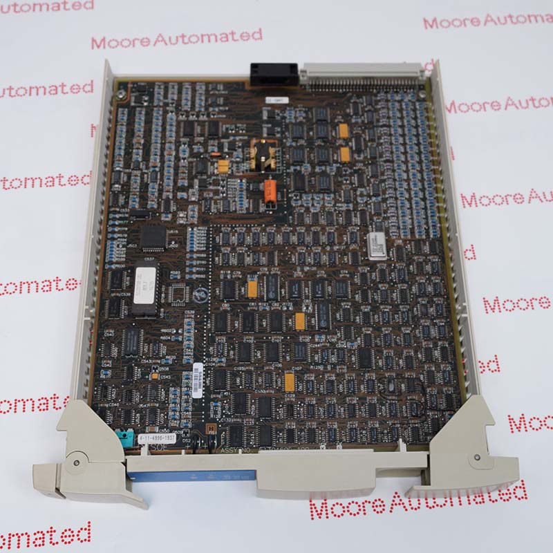
Honeywell MU-TAMR03 51309218-125 parameters below are taken from a multi-page technical document that identifies the model. Verify the supplied hardware revision before installation.
Honeywell HPM Planning table 12-1 identifies MU-TAMR03 as an LLMux RTD field termination assembly with part number 51309218-125. The manual's field assembly lists show 16 channels and compression terminal type for this model. Its CE parts table also maps 51309218-125 to the RTD FTA, while the coated MC-TAMR03 51309218-175 is a separate assembly. These are exact-model catalog facts; they do not establish the RTD sensor type, wiring resistance allowance, measurement accuracy or calibration for a particular installation.
The Honeywell LLMux diagram places the RTD FTA on the field side of a separate MU-TLPA02 power adapter and MU-PLAM02 IOP. Honeywell states that the LLMux component family does not interchange with RHMUX assemblies. For a planned exchange, identify the actual FTA label and revision, sensor wiring, channel assignments, terminal positions, adapter, IOP, cable and cabinet design. Follow plant isolation and current manufacturer procedures, then verify every affected temperature input against the actual connected RTDs. Do not infer thermocouple cold-junction specifications from the neighboring TAMT FTA or claim the termination assembly independently performs the IOP's signal processing.
Honeywell HPM Planning table 12-1 prints MU-TAMR03 and 51309218-125 on the same LLMux RTD FTA row. Another catalog table lists the part under CE-compliant non-coated FTAs. These manufacturer entries support the exact order identity without borrowing an MC model number. Verify the physical label and revision of the offered unit, since the historical catalog does not certify present stock condition.
The manufacturer FTA listings associate MU-TAMR03 with 16 RTD input points and compression terminals. This describes a field termination assembly rather than a standalone measuring processor. Actual sensor curves, input accuracy and configured channel behavior depend on the installed IOP and engineering configuration. Confirm the field wiring, RTD type, point assignments and approved system drawings before reconnecting any sensor.
Honeywell's LLMux diagram shows the RTD FTA connected via a separate power adapter to the LLMux IOP. The planning text says LLMux assemblies are compatible only with each other, not with RHMUX hardware. Record the adapter part, processor, cable and cabinet execution before ordering. After controlled replacement, inspect terminals and verify all affected temperature values and diagnostics through the complete installed assembly.
Confirm MU-TAMR03 51309218-125 on the actual FTA and identify the required CE, non-coated execution. Match the 16-point compression-terminal RTD assembly to the installed cabinet and sensor wiring. Identify the separate LLMux power adapter and processor before selecting a replacement. Honeywell lists coated MC-TAMR03 separately and excludes RHMUX substitution. The catalog row does not specify an installed sensor curve, accuracy figure or universal cable arrangement, so those details must come from current plant drawings and manufacturer guidance.
Record the existing FTA label, revision, terminal positions, RTD connections, point mapping, adapter, IOP and baseline temperature indications. Isolate and handle the low-level circuits using authorized site and Honeywell procedures. After fitting the exact assembly, inspect wiring and terminal security, then test the affected RTD values and diagnostic states against known process conditions. Do not carry a thermocouple FTA's cold-junction data into this RTD product or assume that a similarly named coated assembly is automatically interchangeable.

Registered Address: 32D Floor Guomao Building, No.388, Hubin South Road, Siming District, Xiamen,Fujian, China
MooreAutomated.com is the official website and primary online platform operated by Moore Automation Limited. The website provides information about the company’s industrial automation parts sourcing services, product coverage and customer support. Moore Automation Limited operates as an independent supplier and is not an authorized distributor or representative of the manufacturers displayed on this website unless expressly stated.