Registered Address: 32D Floor Guomao Building, No.388, Hubin South Road, Siming District, Xiamen,Fujian, China
ISO 9001:2015 Certified
Our quality management system covers sourcing,testing and dispatch

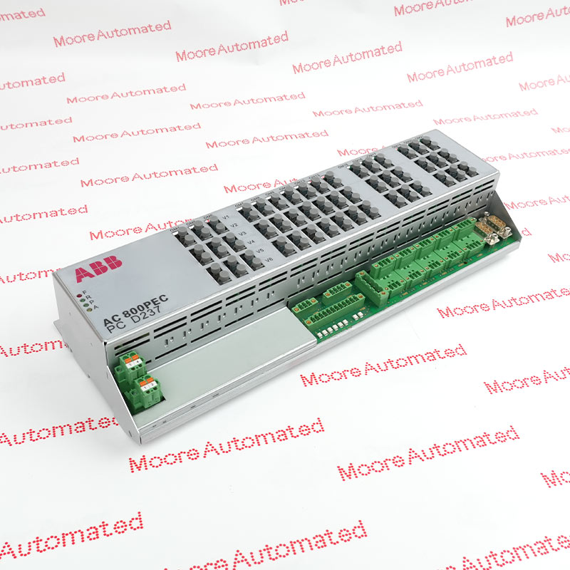
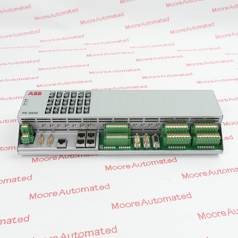
3BHE029153R0101 UNS0119A-P,V101 is an ABB network communication board used with the documented UNITROL Excitation Systems platform. Selection must match the complete product identity, hardware execution, connected assemblies and approved system configuration.
Before replacing 3BHE029153R0101 UNS0119A-P,V101, compare the supplied nameplate, revision, connectors or terminals and installed position with the original equipment record. After installation, review diagnostics and complete the approved functional checks before service.
3BHE029153R0101 UNS0119A-P,V101 is an ABB network communication board selected by its complete product identity and documented equipment role. Its suitability depends on the installed UNITROL Excitation Systems system, hardware execution, interfaces and application requirements matching the supplied unit. Visual similarity or a shortened code is not proof of interchangeability.
Before replacing 3BHE029153R0101 UNS0119A-P,V101, record the full nameplate, installed position, connector or terminal arrangement, paired equipment and relevant ABB service information. After installation, verify power, communication and control interfaces, complete the approved functional checks and confirm stable operation before returning the equipment to service.
ABB 3BHE029153R0101 UNS0119A-P,V101 documentation and reference links.
Important Notice: Every linked document must identify the listed model or its documented family. Confirm the complete order code, hardware revision and installed-system requirements before replacement.
This network communication board links the documented excitation-control nodes and communication path. Match the complete ABB identity and receiving-equipment record before installation.
Keep UNS0119A-P,V101 on the documented signal, bus or power path. Preserve connector orientation, installed position and approved settings.
After replacement, compare diagnostics with the saved baseline and prove the assigned network communication board function under controlled test conditions.
Trace the documented field, bus or power path through the installed network communication board. Verify terminal ownership, connector orientation and receiving-equipment reference before energization.
Capture the installed diagnostic baseline before exchange. After startup, compare status indications and prove that the assigned function responds correctly before removing the test boundary.


Registered Address: 32D Floor Guomao Building, No.388, Hubin South Road, Siming District, Xiamen,Fujian, China
MooreAutomated.com is the official website and primary online platform operated by Moore Automation Limited. The website provides information about the company’s industrial automation parts sourcing services, product coverage and customer support. Moore Automation Limited operates as an independent supplier and is not an authorized distributor or representative of the manufacturers displayed on this website unless expressly stated.