Overview
Manuals
Main Features
Replacement Procedure
Features:
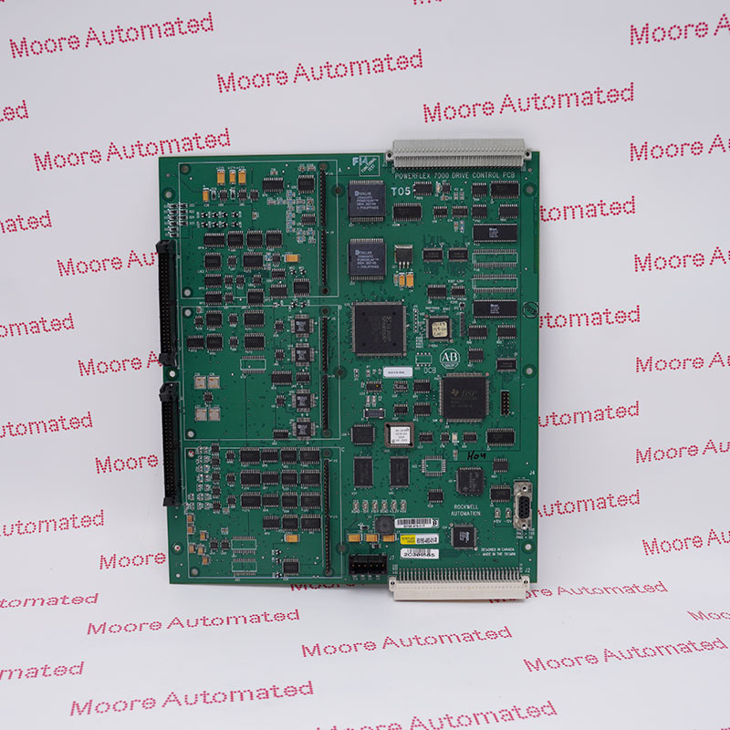
- Drive Processor Module (DPM) board assembly
- PowerFlex 7000 Medium Voltage AC Drive
- It is a critical control component specifically designed for use in PowerFlex 7000 Drive Series
The control hardware includes a Drive Processor Module (DPM) that connects to six Optical Interface Boards (OIBs) via an Optical Interface Board (OIBB) (the exact number depends on the voltage and the number of switching devices). It also includes an Analog Control Board (ACB) and an External I/O Board (XIO). This control hardware is used for rectifier and inverter, inductive or synchronous drive control, and all configurations.
The DPM features two floating-point DSPs (Digital Signal Processors) and one FPGA (Field Programmable Gate Array) for implementing advanced functions such as gating and diagnostics, fault handling, and drive synchronization control.
The 80190-580-01-RAllen Bradley Drive Processor Board may still be available for purchase and support from Moore Automated Company beyond End-Of-Life (EOL) by the manufacturer (OEM).
Allen Bradley 80190-580-01-R Drive Processor Board manual(Datasheets), Link
Important Notice: Other accessories, manuals, cables, calibration data, software, etc. are not included with this equipment unless listed in the above stock item description. All prices are shown in USD.
This board contains the control processors. It is responsible for all the drive control processing and stores all of the parameters used for the drive control.
1. If possible, record all driver setup information using any of the above options.
2. Ensure all medium and control voltage power supplies to the driver are isolated and locked.
3. First, remove the transparent cover on top of the driver processor module by unscrewing the four screws.
4. Use an anti-static wrist strap before removing any connectors.
5. Correctly identify and label (if necessary) connectors J4, J11, and J12 before removing them.Refer to the circuit diagram.
6. Remove the four screws at the four corners that secure the board to the Analog Control Board (ACB) bracket.
7. Carefully disconnect the driver processor module from the four 34-pin female connectors and one 16-pin female connector on the ACB.
8. Before replacing the driver processor module, remove the DIM module from the driver processor module (DPM) and insert it into the new driver processor module.
9. Reinstall the circuit board into the low-voltage control cabinet in the reverse order of steps 7 through 3.
10. Apply control power to the drive. The DPM does not come with firmware pre-installed, so the drive will automatically enter download mode. Please follow the instructions in "Install Firmware" to install the firmware on the drive.