

Request a Parts Quote
Name
Company *
Phone *
Email *
Address
City
State / Province / Region
Zipcode
Country
Quantity *
Part Number *
Manufacturer
Preferred Condition
Additional Information
Cancel
Bently Nevada 991-06-XX-01-00 MOD:169955-01
  • ISO 9001:2015 Certified

    Our quality management system covers sourcing,testing and dispatch
  • View Our Success Stories

    Real stories from real customer orders
In Stock
Ships by Saturday, October 24
Fast Shipping Available
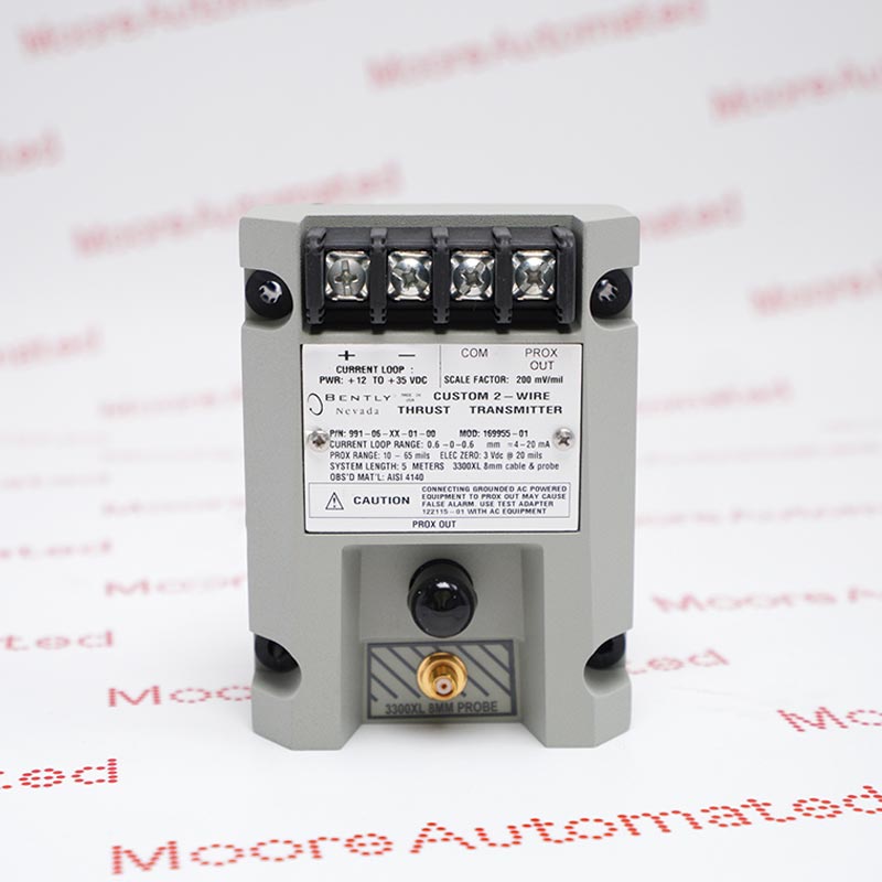
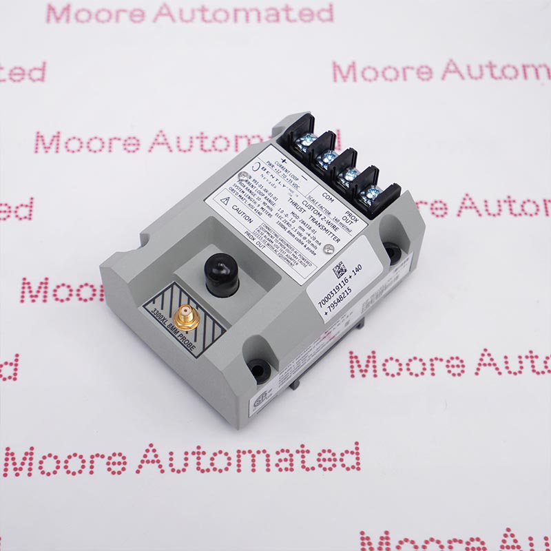
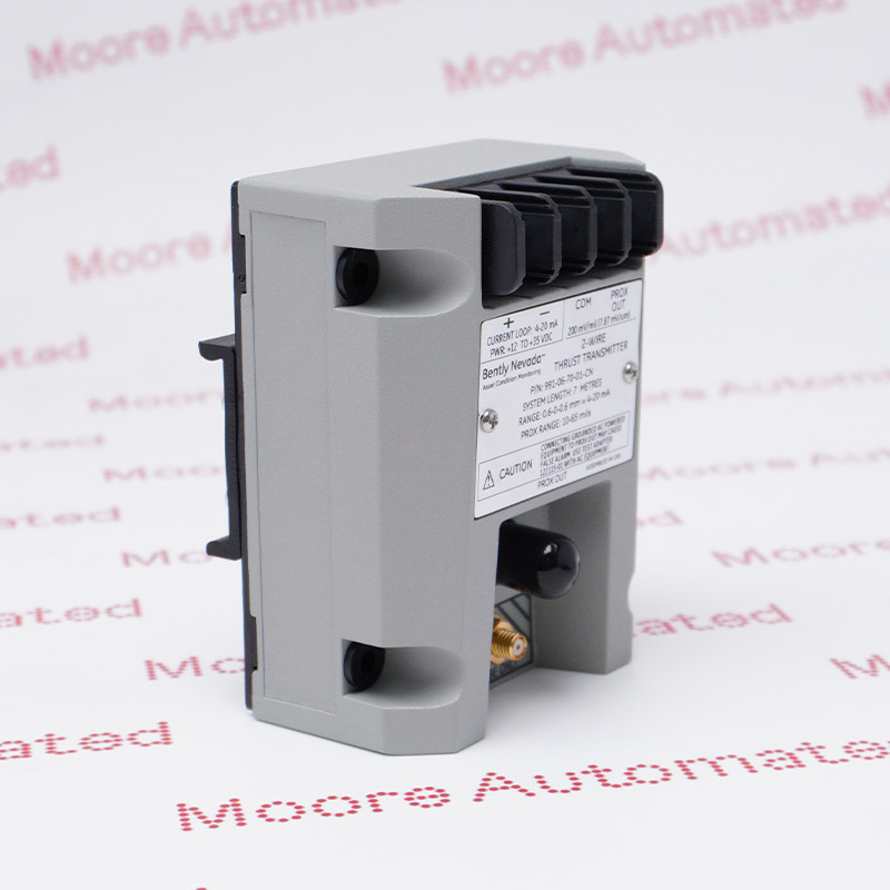
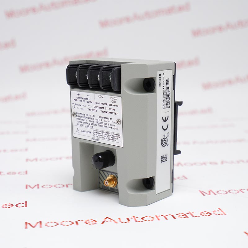
991 Two-Wire Thrust Transmitter

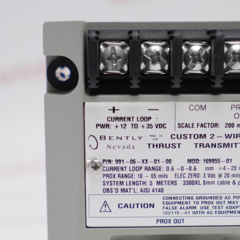
991-06-XX-01-00 MOD:169955-01

Product Information:

991-06-XX-01-00 MOD:169955-01 is a Bently Nevada 991 Two-Wire Thrust Transmitter that converts axial shaft-position/thrust input from one 3300 NSv proximity-probe system into an industry-standard 4–20 mA two-wire loop signal. The ordered full-scale code resolves to 0.6–0–0.6 mm axial position range, and the system-length code resolves to XX — not defined in the current official ordering table; verify the controlled order/MOD record. The retained special marking is MOD:169955-01; its meaning must be confirmed from the controlled order/MOD record.

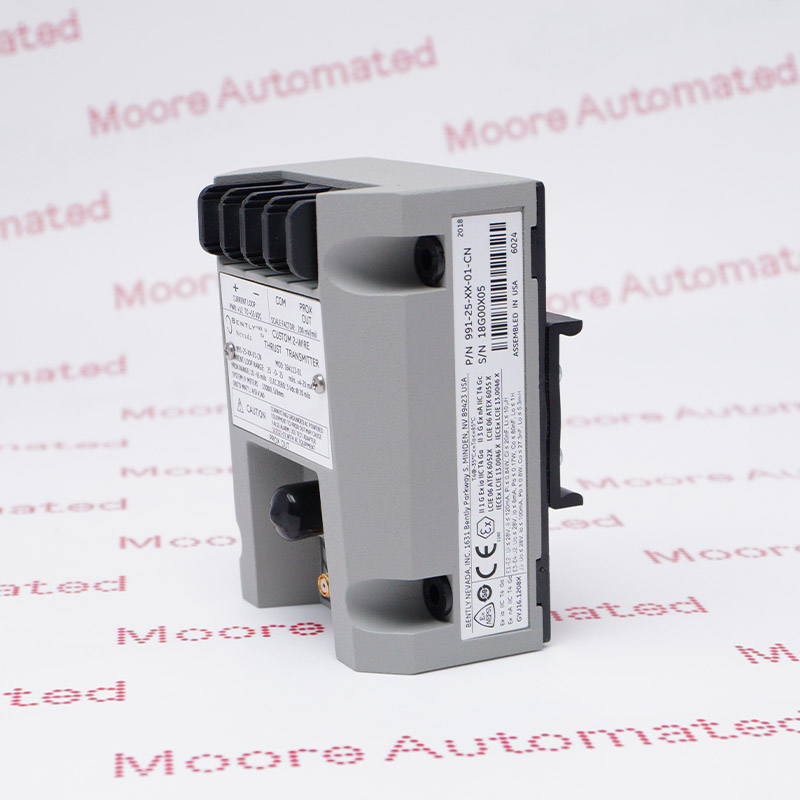
Product image is representative; revision or series may vary. Contact us to request a specific version.
  • One-year warranty
  • Global shipping
  • Exact-model verification
    • PRODUCT OVERVIEW

      What is this product?

      991-06-XX-01-00 MOD:169955-01 is a Bently Nevada 991 Two-Wire Thrust Transmitter that converts axial shaft-position/thrust input from one 3300 NSv proximity-probe system into an industry-standard 4–20 mA two-wire loop signal. The ordered full-scale code resolves to 0.6–0–0.6 mm axial position range, and the system-length code resolves to XX — not defined in the current official ordering table; verify the controlled order/MOD record. The retained special marking is MOD:169955-01; its meaning must be confirmed from the controlled order/MOD record.

      Selection basis

      Match the complete 991-06-XX-01-00 MOD:169955-01 marking, documented function, electrical interfaces and receiving installation before replacement; a similar enclosure does not establish compatibility.
    • APPLICATIONS

      Where it may be used

      Application contexts for 991-06-XX-01-00 MOD:169955-01, based on its documented 991 two-wire thrust transmitter function and recorded execution.

      LNG & Pipeline

      991-06-XX-01-00 MOD:169955-01 provides continuous thrust-position data for pipeline compressors and LNG refrigeration trains.

      Mining & Minerals

      991-06-XX-01-00 MOD:169955-01 tracks thrust-bearing travel on large mills and compressor auxiliaries within 0.6–0–0.6 mm axial position range.

      Chemical Processing

      991-06-XX-01-00 MOD:169955-01 supplies axial-position trending and alarms for critical process trains across 0.6–0–0.6 mm axial position range.

      Refining & Petrochemical

      991-06-XX-01-00 MOD:169955-01 tracks axial movement on process compressors, expanders and large pumps within 0.6–0–0.6 mm axial position range.
Technical specifications for

991-06-XX-01-00 MOD:169955-01

0 TECHNICAL PARAMETERS
  • Manufacturer:
    Bently Nevada
  • Product Family:
    Bently Nevada 991 transmitter
  • Measurement Function:
    Axial shaft position / thrust
  • Full-Scale Option:
    0.6–0–0.6 mm axial position range
  • System Length Option:
    XX — not defined in the current official ordering table; verify the controlled order/MOD record
  • Mounting Option:
    35 mm DIN-rail clips
  • Approval Option:
    agency approval not required
  • Transducer Input:
    One Bently Nevada 3300 NSv probe and extension-cable system
  • Loop Supply:
    +12 to +35 Vdc
  • Signal Output:
    4–20 mA, two-wire current loop
  • Loop Accuracy:
    ±1.5%
  • Maximum Loop Resistance:
    1000 Ω at 35 Vdc
  • Current Limit:
    23 mA typical
  • NOT OK Output:
    Less than 3.6 mA within 100 µs
  • Prox Out Impedance:
    10 kΩ
  • Incremental Scale Factor:
    7.87 mV/µm (200 mV/mil)
  • Prox Out Linear Range:
    0.25 to 1.65 mm (10 to 65 mils)
  • NOT OK Recovery:
    Within 0.1 second after input restoration
  • Special / MOD Marking:
    MOD:169955-01 — retain exactly and verify from the controlled order record
  • Stock Availability:
    4
WHAT HAPPENS NEXT?

From enquiry to delivery

Six clear steps show what information is required and what the written quotation will contain.
  • 01

    Find the product

    Search the part number or send an inquiry for obsolete, discontinued or hard-to-find parts.
  • 02

    Provide the details

    Share the exact part number, quantity, condition, revision, destination and any required certificates or photos.
  • 03

    Review the quotation

    Receive price, currency, condition, availability, warranty, lead time, shipping terms and quotation validity in writing.
  • 04

    Confirm the order

    Accept the quotation in writing and complete the required payment before shipment.
  • 05

    Pay by bank transfer

    Pay the full invoiced amount by bank wire in RMB/CNY, GBP, EUR or USD using the official invoice details.
  • 06

    Verify and dispatch

    The item receives a pre-shipment inspection and suitable protective packaging. Functional testing is performed only where appropriate equipment and procedures are available for the specific item. We confirm the applicable inspection scope and provide tracking after dispatch.
BUYER INFORMATION

Product condition level information

Commercial details are confirmed in writing before payment.
  • 01

    Factory Sealed

    Unused product with the original factory seal intact; packaging age or storage marks may still be present.

  • 02

    Original Pack

    Unused product in original manufacturer packaging that was not originally factory sealed.

  • 03

    Factory New

    New and current product sourced through the manufacturer or authorized supply channel when expressly confirmed in the quotation.

Alternative Names

Bently Nevada 991-06-XX-01-00 MOD:169955-01 991-06-XX-01-00 169955-01 99106XX0100MOD16995501

Information

Overview Manuals Metric Thrust Probe Length Review DIN Std MOD 169955-01

Features:

  • Exact 991-06-XX-01-00 MOD:169955-01 two-wire axial-position/thrust transmitter with a 4–20 mA loop output.
  • Ordered full-scale execution: 0.6–0–0.6 mm axial position range.
  • 3300 NSv system-length and mounting executions: XX — not defined in the current official ordering table; verify the controlled order/MOD record; 35 mm DIN-rail clips.

The 991-06-XX-01-00 MOD:169955-01 accepts one 3300 NSv proximity-probe system and converts axial shaft position into a proportional 4–20 mA current-loop output for thrust-position monitoring. The transmitter operates from +12 to +35 Vdc, supports up to 1000 Ω loop resistance at 35 Vdc, and provides a buffered Prox Out signal for commissioning measurements.

This order code records 0.6–0–0.6 mm axial position range, XX — not defined in the current official ordering table; verify the controlled order/MOD record, 35 mm DIN-rail clips and agency approval not required. Before replacement, preserve the established zero/reference position, verify probe/cable compatibility, loop polarity and scaling, and prove the NOT OK response without changing the machine protection setpoints. The additional marking MOD:169955-01 is retained exactly and must be verified from the controlled order/MOD record because the public ordering table does not decode it.

The 991-06-XX-01-00 MOD:169955-01 Bently Nevada 991 Two-Wire Thrust Transmitter may still be available for purchase and support from Moore Automated Company beyond End-Of-Life (EOL) by the manufacturer (OEM).
Bently Nevada 991-06-XX-01-00 MOD:169955-01 documentation and reference links.Important Notice: Official Baker Hughes/Bently Nevada datasheet 141618 identifies this as a 991 Thrust Transmitter, not a 990 Vibration Transmitter. Confirm the complete nameplate, option codes, connected equipment and required controlled documents before replacement.

991-06-XX-01-00 MOD:169955-01 uses the documented 0.6–0–0.6 mm axial position range execution to convert axial shaft position into its 4–20 mA loop signal. Commission the receiving channel against this exact range, preserve polarity and engineering units, and retain the established thrust datum, alarms and trip logic.

991-06-XX-01-00 MOD:169955-01 records XX — not defined in the current official ordering table; verify the controlled order/MOD record for the matched 3300 NSv probe and extension-cable chain. Confirm the combined electrical length, connector condition, probe gap and buffered Prox Out response before accepting the loop reading.

991-06-XX-01-00 MOD:169955-01 records 35 mm DIN-rail clips with agency approval not required. Match the physical mounting hardware, terminal access, grounding and approval marking, then prove the NOT OK response through the receiving system without changing protection setpoints. Retain the additional marking MOD:169955-01 exactly and verify it against the controlled order or MOD record; the public ordering table does not decode it.

Technical notes

991-06-XX-01-00 MOD:169955-01: Match the complete order and special marking, documented measurement or protection function, connected hardware and electrical interfaces before replacement. Record the installed configuration and prove the complete affected signal, fault and trip path after commissioning.

Axial Position Conversion

The 991-06-XX-01-00 MOD:169955-01 scales 0.6–0–0.6 mm axial position range axial shaft position to a 4–20 mA two-wire output. Preserve the mechanical reference, polarity and thrust alarm positions while verifying the +12 to +35 Vdc supply and total loop resistance at several known displacement points.

Probe Interface and Fault Response

Use the matched XX — not defined in the current official ordering table; verify the controlled order/MOD record 3300 NSv chain and confirm the 0.25–1.65 mm buffered Prox Out linear range without allowing probe contact. An input fault must drive the loop below 3.6 mA within 100 µs and valid input should restore operation within 0.1 second.

Customs & shipping dimensions / weight

  • Packed shipping dimensions
    Confirmed after final packing
    Final packed dimensions are recorded after protective packing for the supplied configuration.
  • Packed shipping weight
    Confirmed after final packing
    Final gross shipping weight is recorded after protective packing.
  • HS / customs code
    9031809090
    Electronic vibration or displacement measurement apparatus; final classification is confirmed by the destination customs declarant.
  • Country of origin
    USA
    Recorded for Bently Nevada products and confirmed against the supplied item marking and shipment documents.
  • Ships from
    Xiamen, Fujian, China
    The dispatch location, quantity and handling time are confirmed in the written quotation.
  • Customs documents
    Confirmed for the destination
    Invoice, packing-list and origin-document requirements are agreed with the order.
PRODUCT & ORDER FAQS

Questions buyers ask about 991-06-XX-01-00 MOD:169955-01

  • How should the axial-position endpoints for the 06 full-scale code be established?

    Reference the machine thrust datum and apply approved displacement checks across the ordered 0.6–0–0.6 mm axial position range range, confirming loop current, polarity and receiving engineering units at multiple points.
  • How should the established thrust zero/reference be preserved during replacement?

    Record the running and stopped reference values, probe gap/Prox Out voltage, mechanical datum and monitor zero before removal, then reproduce the documented reference without moving alarm setpoints.
  • How should loop supply and maximum resistance be checked before energizing?

    Measure the +12 to +35 Vdc source and calculate all series resistance, including receiving input and barriers, so the complete loop remains within the 1000 Ω limit at 35 Vdc.
  • Which checks confirm the ordered 3300 NSv system length?

    Match the probe and extension-cable part numbers to the XX — not defined in the current official ordering table; verify the controlled order/MOD record execution and confirm combined electrical length and connector condition rather than relying on routed cable length.
  • How should NOT OK behavior be tested on a thrust-position channel?

    Use an approved input-fault simulation, verify loop current falls below 3.6 mA within 100 µs and valid input restores operation within 0.1 second, while observing receiving-system fault annunciation.
  • How should the buffered Prox Out linear range be verified?

    Use a high-impedance instrument and controlled mechanical movement to confirm usable response through 0.25–1.65 mm, while maintaining the documented shaft reference and avoiding probe contact.
  • Which polarity checks prevent reversal of thrust direction?

    Move or simulate the shaft position in a known direction, confirm the corresponding Prox Out and 4–20 mA changes, and verify that the receiving display and alarms identify active and inactive thrust directions correctly.
  • Which installation records must be retained for future thrust-channel service?

    Retain the complete order/MOD marking, probe and cable identities, reference gap, loop supply/resistance, polarity, scaling, alarm positions, fault response and final stopped/running baseline.
MORE PARTS IN THE SAME PROJECT?

Search another part number

Use the exact manufacturer number where possible.
WHY BUYERS WORK WITH MOORE AUTOMATED

Clear checks before you commit

Product-specific verification and written commercial details help purchasing and maintenance teams reduce mismatch risk.
  • Pre-shipment inspection

    Products are inspected before dispatch to verify model, condition and applicable specifications.
  • Documentation available

    Product photos, packaging photos, certificates and datasheets can be provided when available.
  • Clear commercial terms

    Condition, warranty, lead time, included items and shipping terms are stated clearly in writing.
  • 20+ years of experience

    Over 20 years of experience in industrial automation and hard-to-source legacy parts.
  • Product Lifecycle Stage

    Exact 991-06-XX-01-00 MOD:169955-01 identity confirmed at quotation

    Moore Automated supplies 991-06-XX-01-00 MOD:169955-01 only after the complete marking, documented function, connected hardware, electrical interfaces and condition are matched to the written quotation. Preserve the existing installation and configuration records before removal and verify the complete signal or protection path after installation.
Trusted by 5,000+ plants worldwide | Backed by our vast inventory of top-tier control parts, drives and servo motors, fast shipments are dispatched to cover your urgent needs. ABOUT US >>
Moore Disclaimer: Moore Automated's sales automation equipment and related solutions are intended for industrial automation and business operational efficiency improvement purposes only. Product information, technical parameters, and application cases are for reference only and do not constitute an absolute guarantee of performance for any specific industry, scenario, or final application. Actual equipment performance may vary depending on factors such as the usage environment, system integration method, and maintenance conditions. Users should confirm compatibility and safety based on professional technical assessments. Moore Automated assumes no liability for any direct or indirect losses caused by improper use, modification, or failure to operate according to specifications, to the extent permitted by law.

Get a quick price for:

991-06-XX-01-00 MOD:169955-01
Quantity
Upload
(gif, jpg, jpeg, png, bmp, doc, docx, xls, xlsx, ppt, pdf, csv)
For more information on how your data is processed and stored by Moore Automated please read our privacy policy.