


MP 3009X
Get A Quote
When you walk up to a dead machine and see a module tagged 1C31227G01 in the cabinet, the wiring diagram for that device is your most valuable piece of paper. It tells you how the card is supposed to be wired, how it ties into the rest of the control system, and what you can safely touch. In a noisy production hall with supervisors asking when the line will be back, that diagram is not an academic drawing. It is your electrical connection reference and your roadmap to getting the plant running again without creating a new problem.
This article walks through how to treat the 1C31227G01 wiring diagram as a reliable connection reference, how it relates to other diagram types, and how to use it for installation, commissioning, and troubleshooting. The focus is industrial automation: PLCs, HMIs, control panels, and factory integration. The principles apply whether 1C31227G01 is an I/O card, an interface board, or another proprietary module, because the discipline of reading and using the wiring diagram is the same.
Training notes from universities and technical portals describe a wiring diagram as the document that shows the physical connections in an electrical system rather than just the functional logic. Tech Note material from the Michigan State University energy group, for example, defines wiring diagrams as detailed representations of conductors, terminals, and devices laid out so installers and technicians can build and service the system accurately. That is exactly the role your 1C31227G01 drawing plays inside the larger project: it tells you which terminal goes to which field wire, what each conductor is labeled, and how it should route through terminal blocks or marshalling panels.
This is different from a schematic or ladder diagram. A schematic or ladder view, as described in resources from Electrical Engineering Portal and NMOERŌĆÖs motor control theory text, focuses on the logical relationship between contacts, coils, and loads. It uses symbols to show what has to be true for a device to energize but hides the physical wire routing. The wiring diagram, by contrast, is concerned with real-terminals and real wires. It tells you that terminal 3 on 1C31227G01 lands on terminal X2:17 in the cabinet and from there goes to a specific field device.
For day-to-day work, you use the wiring diagram when you have a screwdriver and meter in your hand. You use the schematic or ladder diagram when you are trying to understand why something should be energizing but is not. Many modern projects provide both views for the same hardware, because they serve different but complementary purposes.
One 1C31227G01 module can appear on several different diagrams in the documentation set. Industry guides from Electrical Engineering Portal, TestGuyŌĆÖs overview of electrical drawings, and ZukenŌĆÖs discussion of wiring diagram types all describe a consistent pattern.
At the highest level, there is usually a single-line or block diagram. This drawing shows major pieces of the system as blocks or single lines: incoming power, main switchboards, motor control centers, control panels, and sometimes key I/O modules. The 1C31227G01 might appear here as a block to show that it belongs to a particular PLC rack or controller assembly. You do not get terminal-level detail here; you get context. When you are on site, this is the view that tells you which panel and which section of the plant you should be standing in.
A schematic or ladder diagram then shows how the control logic works. Training material from NMOER and ControlByte explains that ladder diagrams use vertical rails and horizontal rungs to depict control circuits, while schematics focus on series and parallel relationships between components. In that logic view, 1C31227G01 might be represented by a coil or function block symbol, showing how signals on the module influence relays, interlocks, or alarms. This is the view you use when you want to understand ŌĆ£what should be happeningŌĆØ from a control perspective.
The wiring diagram is the detailed connection reference. Here you see each terminal, wire number, cable identifier, and destination. Documents from MAEC and Upmation emphasize that wiring diagrams resemble schematics but are more concerned with physical location and terminal identification. For 1C31227G01, this is where you confirm exactly where field conductors land, which terminal strip feeds which signal, and how many wires can occupy a given terminal.
A quick way to mentally separate these drawings is to think in terms of questions. When you want to know ŌĆ£where in the plant is this card and what does it feed,ŌĆØ look at single-line and block diagrams. When you want to know ŌĆ£under what logical conditions should this output energize,ŌĆØ look at schematics or ladder diagrams. When you want to know ŌĆ£where do I land this wire and what should be on this pin,ŌĆØ use the wiring diagram.
The table below summarizes the roles without tying them to any specific manufacturer.
| Diagram type | What it shows for 1C31227G01 | How you actually use it in the field |
|---|---|---|
| Single-line / block | Module as part of a rack, panel, or subsystem | To find the right cabinet and understand system context |
| Schematic / ladder | How module signals participate in control logic | To understand cause-and-effect and interlocks |
| Wiring diagram | Terminals, wire numbers, cable IDs, and destinations | To land wires, verify connections, and troubleshoot with a meter |
On paper, reading wiring diagrams is about symbols and lines. In the field, it is about having a repeatable way to make sense of the drawing while you are leaning into a cabinet with a headlamp on. Training material from Electrical Engineering Portal and MAEC recommends a systematic approach, and the same workflow applies directly to a 1C31227G01 card.
The first step is always the title block and revision information. Confirm you are holding the latest revision and that the drawing actually references 1C31227G01 by tag or part number. Many plants have laminated prints in the cabinet and newer revisions in a maintenance office. If the revision dates or approval stamps do not match, treat the diagram as suspect until you can reconcile it. Tech notes from MAEC and TestGuy both stress that working from outdated prints is a common root cause of miswiring and extended downtime.
Once you are confident you have the correct drawing, look at the legend and symbol list. Basic resources from the University of Florida and Electronics Tutorials show that symbols for switches, fuses, circuit breakers, and control devices are standardized, but there are IEC and NEMA variants and occasional custom symbols. Some vendors use IEC-style rectangles and additional coding; others follow NEMA conventions. The legend tells you how this specific project expresses those devices. You do not want to guess whether a particular symbol is a fuse, a breaker, or a disconnect when you are standing in front of an energized panel.
The next pass is to identify power rails and reference potentials. Articles from ControlByte and UTIŌĆÖs wiring diagram guide emphasize the importance of understanding where voltages and reference nodes are defined in the drawing. Look for labels such as 24 VDC, L1, L2, and various ground symbols, and trace where they enter the 1C31227G01 card. This gives you a mental picture of which terminals you should consider ŌĆ£liveŌĆØ under normal operation and which ones are low-level signals. It also tells you where your meter leads should go when you start measuring.
After that, focus on terminal identifiers and wire numbers. In a good 1C31227G01 wiring diagram, every terminal should have a clear designation and every conductor should have a wire number or cable ID. Practical handbooks, such as those summarized by Electrical Engineering Portal and Tech Note 251, recommend following wire numbers across terminal strips and between sheets rather than chasing line art visually. Doing that with a finger or insulated screwdriver is not just an old-school trick; HVAC technicians and industrial electricians routinely report that physically tracing the path on the diagram dramatically reduces mistakes. The wiring-diagram learning anecdote from HVAC Know It AllŌĆÖs community reinforces this: stop relying only on labels, and force yourself to follow each conductor from source to destination.
Finally, locate cross-references and page references. In multi-page documentation, a 1C31227G01 card may appear on more than one drawing: for example, one sheet for the cabinet side and another for field junction boxes. Cross-reference tags next to terminals or cable identifiers point you to those other sheets. ControlByte notes that cross-references and potential designations are essential in large, mixed-voltage systems. If your wire disappears into a cable symbol and reappears on another page, you want to be sure you are following the same conductor, not a similarly named one.
When you consistently move through drawings in this orderŌĆötitle block, legend, power and reference, terminals and wire numbers, cross-referencesŌĆöyou stop getting lost halfway through and you reduce the temptation to ŌĆ£wing itŌĆØ based on memory.
Even though every project has its quirks, the symbol language around a module such as 1C31227G01 is highly standardized. University-level resources on electrical symbols and commercial guides from sites like Electronics Tutorials and SparkFun highlight the same building blocks: power sources, protective devices, control devices, loads, and connectors.
Near the 1C31227G01, expect to see symbol clusters for the power source that feeds the card, fuses or miniature circuit breakers protecting that feed, and possibly transient suppression or filtering if the module is sensitive. Control devices such as pushbuttons, selector switches, and limit switches are typically shown on schematics and then tied into the module on the wiring diagram via terminal symbols and wire numbers.
Grounding and reference symbols deserve particular attention. Guides on schematic symbols emphasize that earth ground, chassis ground, and digital or signal ground can have different symbols, and they do not always represent the same node. If the 1C31227G01 card interfaces with both field power and low-level signals, misinterpreting these reference points can lead to noise problems or even damage.
Finally, note the reference designations around the module. Articles on industrial diagram coding, such as those referencing IEC 81346 in ControlByteŌĆÖs material, explain that complex systems often label each device with a functional code, location, and element identifier. The 1C31227G01 tag you see on the faceplate may show up in the drawing combined with these prefixes. Once you decode that structure, it becomes much easier to navigate between different drawings for the same piece of hardware.
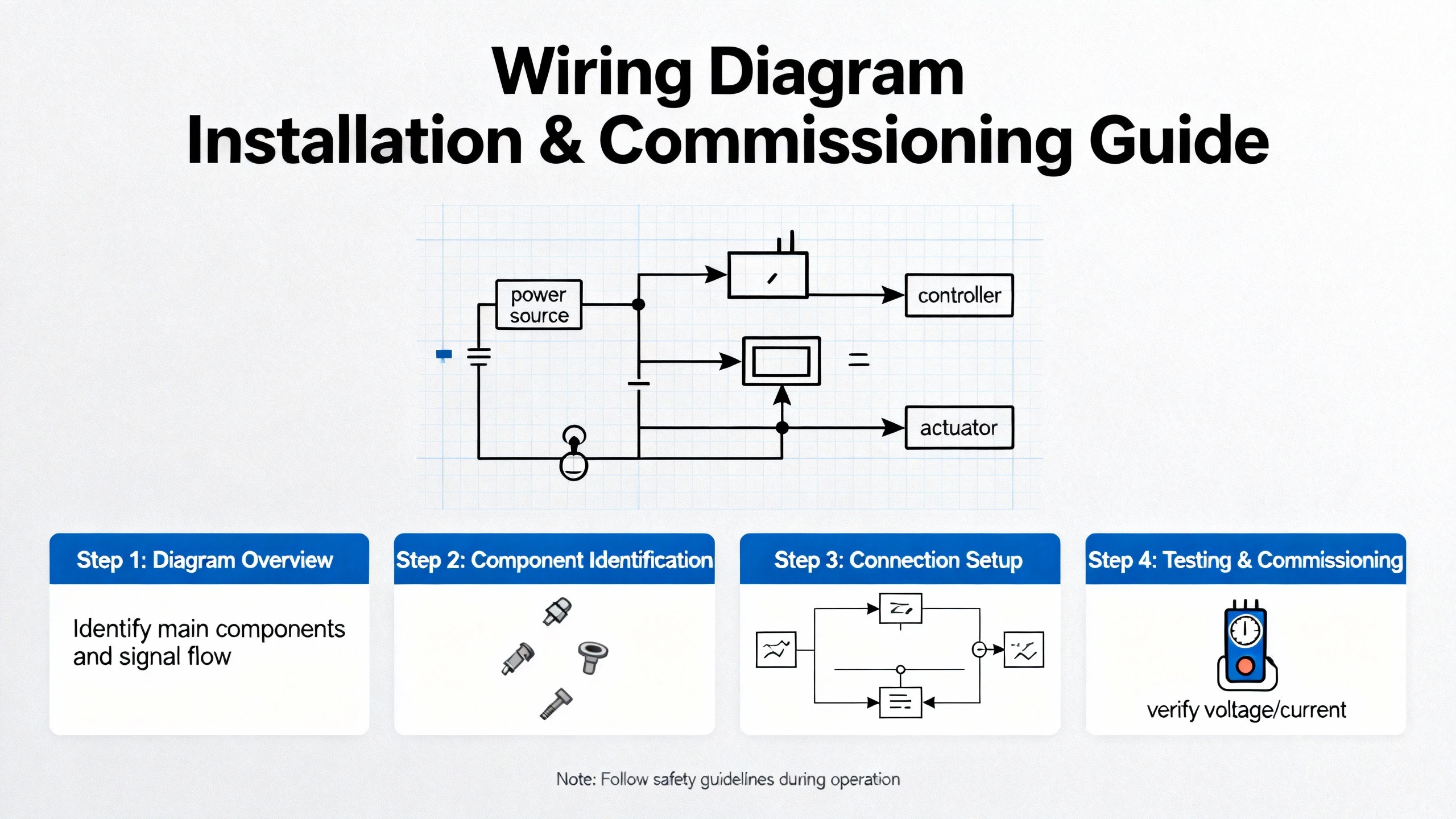
When you are installing a new 1C31227G01 or replacing an existing one during a retrofit, treat the wiring diagram as the contract between design and reality. Practical guides from MAEC and TRDsfŌĆÖs wiring diagram overview suggest a disciplined approach: read the diagram first, then pick up tools.
Start by verifying the supply. Confirm that the card supply voltage on the drawing matches what is available in the panel and that protective devices are sized correctly. Even though the wiring diagram may not show conductor sizing explicitly, it will show breaker or fuse ratings. Cross-checking these against the cardŌĆÖs manual and plant standards avoids nuisance trips and unsafe conditions later.
Next, lay out your conductors and terminations. Following recommendations in wiring diagram training notes, route cables and wires so that the physical layout follows the logic of the diagram as much as possible. This does not mean copying the drawing line-for-line, but it does mean grouping related signals, respecting separation between high and low voltage, and keeping field I/O wiring orderly around the 1C31227G01 terminals. TriMechŌĆÖs discussion of 2D versus 3D electrical design highlights a common issue: traditional two-dimensional diagrams can hide routing conflicts. Being deliberate with routing during installation is how you prevent those conflicts from becoming real-world issues.
As you land each conductor, mark it off against the wiring diagram. Some technicians prefer to physically highlight each wire reference on a printed copy; others use a digital viewer and mark up a copy of the file. The important point is that no connection is made without being cross-checked against the documented terminal and wire number. UTIŌĆÖs instructional material warns that misinterpreting connection dots and line crossings is a frequent cause of wiring errors. Slow, systematic verification is much faster than rework after energization.
Commissioning is where the wiring diagram and your meter come together. Before applying power, use the diagram to identify which terminals should show continuity and which should be isolated. Verify that no unexpected shorts exist between adjacent terminals and that protective devices are in the correct state. Once preliminary checks pass, energize the panel and measure the actual voltages at the 1C31227G01 supply and I/O terminals, again comparing to the connection reference. This is not blind trust in the drawing; it is using the drawing as a hypothesis and your measurements as the verification.
When a machine stops unexpectedly and alarms point toward a card such as 1C31227G01, the wiring diagram becomes your fault-tree. Guides from Upmation and UTI both recommend starting at the power source and tracing forward through protection, switches, and loads. That same logic applies here but focused on the moduleŌĆÖs terminals.
Begin by confirming supply and reference at the module. Use the diagram to identify which terminals carry power and common or neutral. Measure those points first. If the module is not even powered correctly, you can ignore the rest of the diagram temporarily and work backward along the supply path that the drawing shows.
If supplies are correct, move to the specific channel or signal involved in the fault. The wiring diagram tells you which terminal corresponds to that signal, which wire number or cable is associated with it, and where that conductor goes in the field. Many electricians, including those featured in HVAC training communities, swear by a simple method: remove the conductors involved, label them, and follow each one by finger on the diagram from the module out to the load or sensor. This method feels slow at first, but it forces your brain to align the real wiring with the documented wiring instead of guessing based on wire color or past experience.
This is particularly important in older plants where undocumented changes have been made over the years. TestGuyŌĆÖs coverage of as-built drawings emphasizes that installations often drift away from original designs. If you find a discrepancy between the 1C31227G01 wiring diagram and what you see in the panel, annotate it and treat it as a potential root cause: either the field wiring is wrong, or the documentation is stale. In both cases you have discovered something valuable.
Throughout troubleshooting, resist the temptation to treat the wiring diagram as abstract art. Every symbol and wire number should map to something you can touch or measure. When the diagram and the plant do not match, that mismatch is a data point, not an annoyance.
Since part numbers such as 1C31227G01 can represent different modules in different projects, you must always rely on the manufacturerŌĆÖs documentation for exact pinouts and ratings. However, the way terminal information is presented is usually similar. To understand how to use a wiring diagram as an electrical connection reference, it helps to look at a generic layout.
The table below is an illustrative example of how a moduleŌĆÖs terminals might be documented. It is not a specification for any particular product, but it reflects common practice described in wiring diagram guides.
| Terminal | Typical label example | Field connection example | Notes for the technician |
|---|---|---|---|
| 1 | DI1+ | Field switch contact | Verify dry contact versus powered input before wiring |
| 2 | DI1ŌĆō | Common return for DI1 | Check that common reference matches rest of control circuit |
| 3 | DI2+ | Limit switch at conveyor end | Confirm shielding and routing away from motor cables |
| 4 | DI2ŌĆō | Common return for DI2 | Match wire number to terminal strip reference |
| 5 | COM24V | 24 VDC common | Measure reference level before tying multiple circuits in |
| 6 | +24V | 24 VDC supply from panel power supply | Protected by fuse F1 shown elsewhere in the drawing |
In a real 1C31227G01 wiring diagram, the ŌĆ£Typical label exampleŌĆØ and ŌĆ£Field connection exampleŌĆØ columns would be driven by the actual specification. Your job on site is to treat the table and associated graphics as the truth for connection points, and then verify that the plant wiring and your measurements agree.
Using the 1C31227G01 wiring diagram as your main connection reference has significant advantages. As multiple sources, including TRDsf and MAEC, point out, wiring diagrams give clear visual guidance, improve safety, and reduce time spent guessing at connections. When a diagram is accurate and well maintained, you can land wires, plan modifications, and troubleshoot faults with far less risk and downtime.
There are tradeoffs, however. Diagrams can become complex as systems grow, making them intimidating for less experienced technicians. They are two-dimensional representations of a three-dimensional cabinet or machine, so they cannot fully convey routing constraints or physical interference. TriMechŌĆÖs discussion of schematic design tools notes that relying only on 2D drawings can leave a lot to the installerŌĆÖs experience and judgment, especially in tight panels.
Another limitation is that wiring diagrams age quickly if changes are not captured. TestGuyŌĆÖs explanation of as-built drawings stresses that every modification to the field installation should be reflected in updated drawings and properly approved. In practice, many facilities have cabinets where the wiring diagram on the door no longer matches the wiring inside. That does not make the diagram useless, but it does mean that you must use it in combination with field verification.
Despite these drawbacks, the alternativeŌĆöworking without a wiring diagram or with scattered notesŌĆöis far worse. A consistent, maintained 1C31227G01 wiring diagram is still the safest and fastest way to understand how the module is connected in the real world.
From a plant maintenance perspective, a wiring diagram is not finished when the project is commissioned. It becomes a living document that should follow the life of the equipment. Tech Notes on wiring diagrams and blueprint management recommend formal processes: control revisions, capture redlines from field changes, and regularly replace outdated prints in cabinets.
For a 1C31227G01 module, this means that whenever a signal is repurposed, a cable is rerouted, or a supply is changed, someone must update the wiring diagram and push that revision through the organization. That might involve CAD tools such as those highlighted by TriMech and Zuken, or it might be a more manual drafting process in smaller facilities. The key is that the drawing you rely on during a night-shift emergency is the same drawing that reflects the current state of the panel.
In many plants, the most reliable record of reality is the electricianŌĆÖs red-marked copy, not the pristine PDF in an engineering folder. Turning those marks into official revisions and keeping both digital and printed sets aligned is unglamorous work, but it pays off every time someone has to touch the 1C31227G01 or its wiring under pressure.
Check the revision block and approval dates on the drawing, and compare them to any change records or modification tags on the panel. If you see extra wires, devices, or labels in the cabinet that do not appear on the diagram, assume the drawing is out of date until someone reconciles it with the installation. Training material on as-built documentation consistently warns against trusting unverified prints.
Treat the discrepancy as a fault condition, even if the machine currently runs. Document exactly what is different, use your meter to confirm which connections are actually in use, and escalate the need for a drawing update. In the meantime, rely on measurements rather than assumptions. Wiring diagram guides from MAEC and TRDsf recommend marking up a copy of the drawing in the field, then feeding that back to engineering for a formal revision.
Color codes are helpful but not reliable on their own. Over time, repairs and modifications can introduce nonstandard colors, and in some cases wire color is reused for different functions. Training notes and field anecdotes, including HVAC-focused learning stories, show that technicians who rely primarily on color tend to miswire more often than those who follow the drawing and wire numbers. Use color as a hint, but let the wiring diagram and your meter have the final say.
In a real plant, the 1C31227G01 wiring diagram is not just a drawing in a binder. It is the bridge between design intent and the tangle of wires you see in the cabinet at 2:00 AM. If you take the time to read it systematically, verify it against reality, and keep it updated, it becomes a trustworthy electrical connection reference that saves you hours of downtime and a lot of guesswork. As an on-site automation engineer, I will take a clean, accurate wiring diagram over a perfect memory every single day.


Copyright Notice © 2026 mooreautomated.com All rights reserved,Moore Automated is not an authorized distributor or representative of the manufacturers featured on this website. Brand names and trademarks featured are the property of their respective owners.


Leave Your Comment