


MP 3009X
Get A Quote
Heidenhain encoders sit right at the heart of many CNC machines, machining centers, robots, and precision stages. When their feedback drops out, the control does exactly what it should do: it shuts you down. From the operatorŌĆÖs perspective, that looks like a mysterious ŌĆ£encoder fault,ŌĆØ ŌĆ£feedback error,ŌĆØ or ŌĆ£encoder lossŌĆØ alarm. From the maintenance side, it is a race against lost production.
In this guide, I will walk through how I approach Heidenhain encoder signal loss on the shop floor, combining practical field workflow with what is documented by Heidenhain and independent repair houses such as Baiza Automation, ACS Industrial Services, Dynapar, and Roc Industrial. The focus is on diagnosis, safe repair decisions, and how to avoid repeat failures.
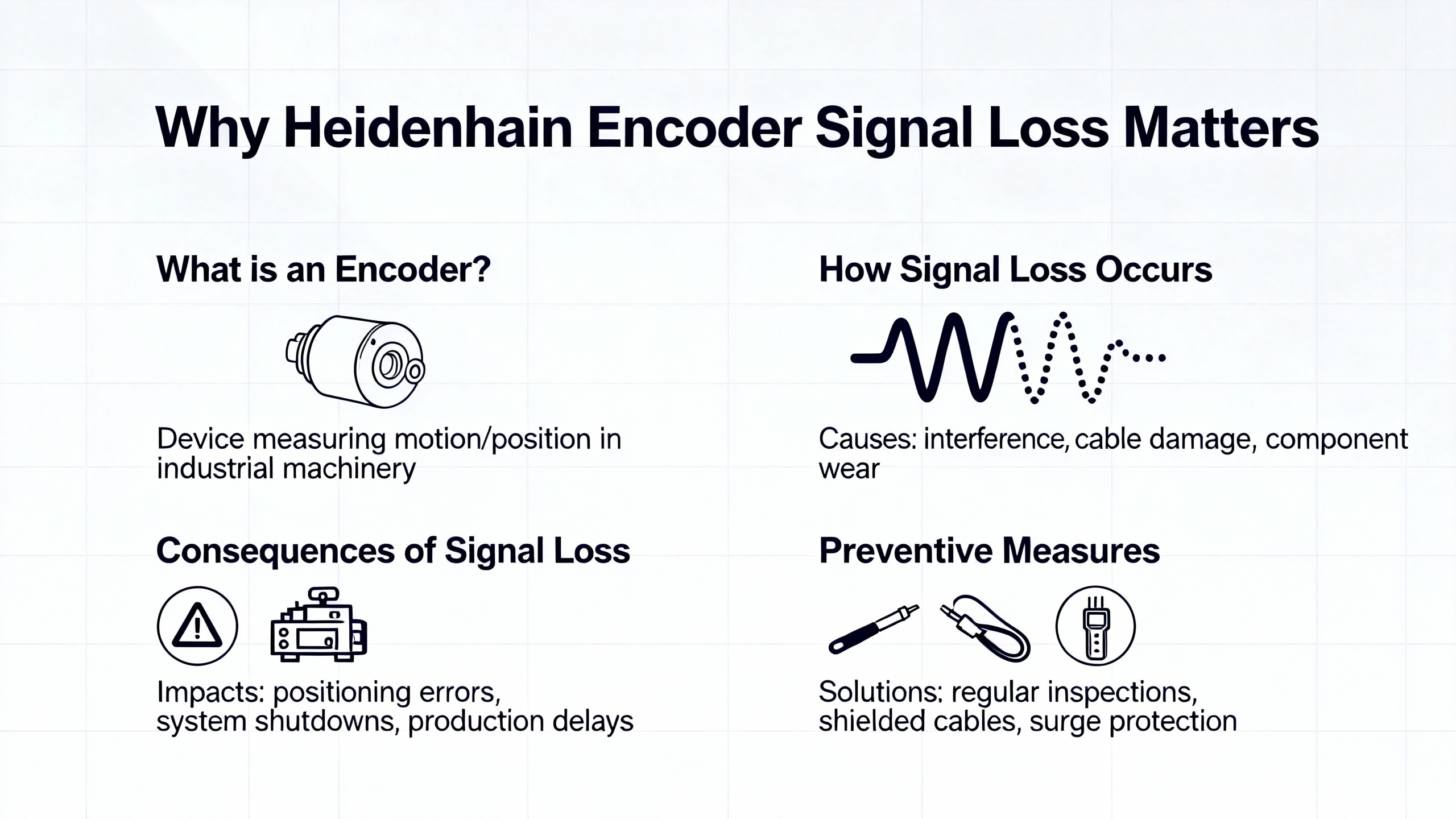
Heidenhain encoders are highŌĆæprecision feedback devices that report shaft or axis position, speed, and direction into your CNC, drive, or PLC. ACS Industrial notes that failures in these encoders can cause major downtime and production losses, because the control will not move a highŌĆæenergy axis if it is not confident about where it is.
Encoders close the loop between the mechanical axis and the servo amplifier. Roc Industrial points out that when a Heidenhain servo amplifier loses encoder feedback, you do not just get an alarm; you lose the ability to control torque and position safely. That is why so many machines are programmed to fault and inhibit motion at the first hint of encoder signal problems.
Signal loss is not always a dead encoder. Baiza Automation and several troubleshooting guides stress that many ŌĆ£dead encoderŌĆØ calls end up being loose connectors, incorrect supply voltage, wrong signal type wiring, or damaged cables. Very often, the encoder itself is still serviceable.
From a maintenance standpoint, that is good news. It means that if you follow a disciplined diagnostic process, you can often recover from a Heidenhain encoder fault quickly without immediately pulling the motor or ordering an emergency replacement.
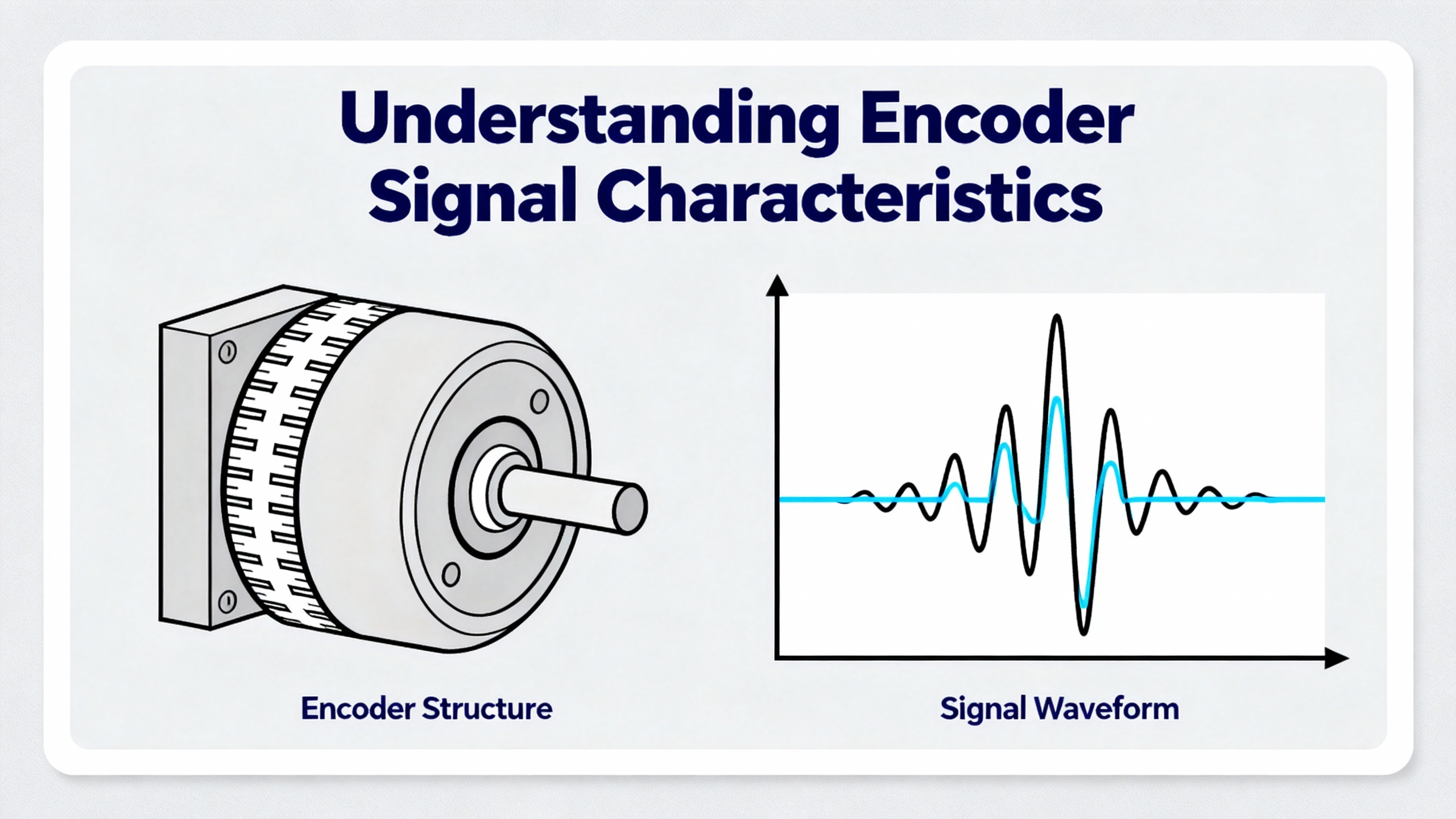
Before you can diagnose signal loss, it helps to be clear on what ŌĆ£normalŌĆØ should look like. The research set here covers a few common Heidenhain signal types and test methods.
Across the sources, Heidenhain encoders show up in both incremental and absolute roles. Incremental encoders output quadrature channels (A and B, sometimes plus complements) and often a reference mark. These can be digital square waves or lowŌĆælevel analog sine/cosine signals like the 1 Vpp outputs discussed in LinuxCNC and Practical Machinist threads.
Absolute encoders, discussed in Heidenhain selection and optimization articles, present a position word over a serial interface such as EnDat or driveŌĆæspecific links. Instead of counting pulses, the control reads out the absolute position from the encoder every cycle.
In both cases, loss or degradation of these signals can lead to lost counts, bogus positions, or complete encoder loss faults.
The LinuxCNC forum case describes probing a Heidenhain LS403 1 Vpp signal on a real milling machine. That encoder produces lowŌĆælevel analog sine/cosine signals, which typically run through an interface board powered at around 12 V. In that field report, the technician discovered that an assumed ŌĆ£unusedŌĆØ 12 V pin on the board was likely required to power signal conditioning, which explains why the 1 Vpp outputs were not behaving.
Other Heidenhain resources and test articles mention a range of interfaces: 1 Vpp analog, TTL digital, 11 ┬ĄApp current signals, and serial interfaces like EnDat as well as driveŌĆæspecific protocols. Walker Machinery and HeidenhainŌĆÖs own optimization pieces emphasize that the encoder and control need to be paired correctly, including matching electrical format and protocol.
If the encoder and interface type do not match what the drive expects, it can look exactly like signal loss even when the encoder is healthy.
DynaparŌĆÖs troubleshooting guide on lowŌĆæamplitude encoder signals gives a clear picture of what the electronics see in a failure case. A very low amplitude square wave that is barely visible but still ŌĆ£looks rightŌĆØ in shape usually points to open wires in the encoder wiring, very often at terminals or connectors rather than inside the encoder.
They also highlight a pattern where the trace you see is not a real channel at all, but crosstalk from neighboring channels that still have good contacts. When a channel wire is open, stray coupling lets the neighboring signal bleed in, creating a faint ghost waveform.
In contrast, a truly flat line on a channel usually indicates a fully open wire at the receiving device end.
On the opposite side of the problem space, Practical Machinist reports a highŌĆæspeed spindle with HeidenhainŌĆæstyle sine/cosine signals specified for 1.0 Vpp. In that case, roughly 1.2 Vpp was measured, enough to overdrive the driveŌĆÖs input stage and clip the sine waves. The drive then could not reliably compute rotation direction and threw an alarm, which is a different but related form of ŌĆ£signal not usable.ŌĆØ
HeidenhainŌĆÖs own testing hardware, such as PWM 20 and PWM 21 used with ATS (Adjustment and Testing Software), is designed to visualize these signals and compare amplitudes and shapes to Heidenhain specifications. Test and measurement articles describe how ATS can take over much of the oscilloscopeŌĆÖs role when diagnosing Heidenhain encoders, both on a bench and on the live machine.
With that picture in mind, we can look at how to approach diagnosis step by step.
When I am called to a line with a Heidenhain encoder alarm, I do not start with exotic failure modes. I start with the mundane, because most encoder problems turn out to be simple faults in the wiring, power, or installation. The sources here align with that experience.
The first thing is to capture what the control and drive are complaining about. Roc Industrial notes that Heidenhain servo amplifiers will distinguish between faults like overvoltage, overcurrent, and encoder loss or feedback faults. The wording of the alarm plus any numeric fault codes on the CNC or drive front panel are your clues.
I also want to know when the problem appears. If the encoder fault happens immediately at powerŌĆæup, that points toward missing power, a completely open cable, or incorrect interface configuration. If it appears only when the axis moves or only at higher speeds, that points more toward mechanical issues, noise, contamination, or marginal signal amplitude.
ACS Industrial emphasizes documenting the encoder make, model, and specific symptoms when seeking repair. That same documentation helps internal troubleshooting too.
Most encoders that ŌĆ£do nothingŌĆØ are not actually dead; they are unpowered. Baiza Automation, ACS, and general troubleshooting guides all point out that loose or insecure electrical connections are one of the most common encoder issues, and verifying supply voltage and wiring is the first pass.
On the machine, I start by confirming that the expected supply voltage is present at the encoder connector under load. That comes straight out of the Heidenhain manual for the specific unit and interface board. If there is a dedicated 12 V pin on an interface board, as in the LinuxCNC LS403 case, you need to confirm whether that pin actually needs to be energized for the signals to be usable and what its acceptable range is.
Yumoelectric and Qingong both highlight wiring faults as a recurring cause of signal interruption. Loose terminals, corrosion on pins, broken conductors at strain reliefs, or wires with too little exposed metal to make proper contact in terminal strips all show up in practice. Dynapar adds that open wires are the most common cause of very low amplitude encoder signals, rather than a defect inside the encoder.
At this stage, I usually reŌĆæseat connectors, inspect pins for damage or contamination, and gently tug on wires to catch broken conductors at crimps. In many cases, tightening a screw terminal or reŌĆæterminating a bad crimp resolves the encoder alarm without touching the encoder body.
Once the obvious connector issues are ruled out, I use a multimeter to confirm basic electrical health, as recommended by Qingong and Yumoelectric.
That means verifying that the supply is within tolerance at the encoder under load and that grounds are solid. It also means performing continuity tests from the encoder connector back to the drive or interface board on each signal line. An open on any of the A, B, reference, or serial lines can mimic encoder failure.
Resistance measurements may reveal shorts between channels or to ground, which suggests damaged cables or misŌĆæwiring. These basic checks do not require specialized equipment and can save a lot of time by distinguishing cable faults from encoder faults.
If the wiring checks out but the drive still reports encoder faults, the next move is to look at the signals directly. Qingong recommends using an oscilloscope to probe encoder outputs and look for irregularities such as distorted signals, improper phasing, or electrical noise.
DynaparŌĆÖs guide on low amplitude encoder signals is particularly useful here. If a channel shows a tiny, hardly visible waveform that still looks like a square wave, it is very likely that the wire for that channel is open at one end and what you are seeing is crosstalk from adjacent channels. When two channels are open, both may show strange interference, but the key clue from Dynapar is that the two traces will not match exactly; if two signals are identical, the problem is probably elsewhere.
On the other hand, if a channel is completely flat at the drive input, that strongly suggests an open at that end of the wire. Dynapar notes that this flatŌĆæline symptom is the more intuitive sign of a broken or disconnected line.
The Practical Machinist example adds the opposite scenario: an analog sine/cosine encoder whose amplitude is higher than the drive can handle. When the measured amplitude sits above the driveŌĆÖs specified limit, the peaks clip and the drive cannot reliably compute position or direction, which can throw alarms that look like generic encoder errors. That is why checking amplitude against the drive and encoder specs is as important as checking shape.
HeidenhainŌĆÖs PWM 20 and PWM 21 tools, together with ATS software, essentially automate this step. Test and measurement articles describe how ATS recognizes the encoder interface type, runs supported diagnostic tests, and shows analog and digital signal quality in dedicated views. A later Heidenhain resource on the ATS ŌĆ£ProtocolŌĆØ feature explains how you can consolidate analog, recording, and PWT measurements into a single test record and save it as a PDF. In a production facility, that is useful both for rootŌĆæcause analysis and for documenting that a repaired encoder meets specification.
Even when the scope shows trouble, you still need to decide whether the encoder itself is at fault or whether the problem lies in the drive, the interface board, or the control.
Baiza Automation and Qingong both recommend swapping the suspect encoder with a knownŌĆægood unit whenever possible. If the encoder fault follows the encoder to another axis or a bench test setup, the encoder is likely bad. If the fault stays on the original axis with a knownŌĆægood encoder, the drive, interface, or wiring harness is suspect.
Another crossŌĆæcheck comes from systems with multiple encoders on the same type of card. If only one channel misbehaves, but the others on the card look clean and the drives do not alarm, you lean toward a local encoder or cable issue. If several encoders on that card show similar noise or loss, the drive or interface hardware may be failing.
Roc IndustrialŌĆÖs discussion of servo amplifier repair reminds us that amplifier faults and encoder faults can intertwine. A failing amplifier input stage can distort or misread an otherwise healthy encoder signal, and an encoder with sporadic output can cause a perfectly good amplifier to alarm and shut down repeatedly. Distinguishing the two through swaps and tests is critical for an efficient repair.
So far, the focus has been on electronics. In practice, a lot of Heidenhain encoder signal problems originate from mechanics and environment.
Baiza Automation calls out wornŌĆæout ball bearings in or around the encoder as a source of irregular drive behavior. In that scenario, the frequency inverter is constantly correcting for missing or inconsistent pulses. Over years, normal aging or poor bearing installation can lead to premature wear, mechanical wobble, and intermittent signal loss.
Yumoelectric also highlights excessive vibration and shock as a cause of encoder problems. If an encoder is rigidly mounted to a structure with strong shocks or resonances, vibration can both shorten bearing life and shake loose marginal terminal connections. The result, from the controlŌĆÖs point of view, is missing counts or intermittent encoder loss alarms.
Proper mechanical mounting and alignment, as emphasized by Heidenhain optimization articles and Walker Machinery, reduces the stress on bearings and the motion of the sensing head relative to its scale or disc. In the long term, that translates into more stable signals.
Baiza Automation describes how dirt and dust contamination on an incremental disc can make the encoder generate one pulse too few or fail to rotate properly because particles cause two increment lines to be read as one. In other words, contamination can selectively erase or distort encoder transitions and cause lost counts long before the encoder dies outright.
Moisture is another recurring theme. Baiza notes that moisture contamination often enters through the cable gland and typically leads to sporadic or intermittent encoder failures. That matches what many of us see on machines in humid or wet areas: encoders that behave perfectly when dry but fault after washdown or in the morning when condensation is present.
QingongŌĆÖs article on encoder maintenance recommends controlling environmental factors such as dust, moisture, and temperature, along with inspecting connectors and seals, to extend encoder life.
Sealed encoders, as discussed in Heidenhain optimization pieces and Walker MachineryŌĆÖs guidance, add housings and sealing lips to protect the measuring standard from chips, coolant, and dust. That does not eliminate the need for proper cable management and sealing, but it greatly reduces contamination ingress.
Baiza Automation warns about overheating or heat damage when hot exhaust air from a motor fan constantly passes over the encoder. Over time, that can cause total encoder failure. Even before total failure, elevated temperatures can shift electronic thresholds and contribute to marginal signal levels.
HeidenhainŌĆÖs product literature, summarized in optimization articles, specifies operating temperature ranges and highlights sealed encoders designed to resist coolant and oil. Running encoders outside their rated thermal envelope is a recipe for sporadic faults that are hard to reproduce in a cooled shop.
In the field, simple changes like shielding an encoder from direct exhaust flow or moving vulnerable cable runs away from hot components can significantly improve reliability.
The following table consolidates recurring patterns from the cited sources and field experience into a quick reference.
| Symptom at drive or test equipment | Likely underlying causes (from sources and field cases) | Suggested next checks |
|---|---|---|
| No feedback at all, alarms immediately at powerŌĆæup, flat line on measured channels | No supply voltage or wrong supply level, unplugged connector, fully open wire at receiving device, incorrect interface type configured | Confirm encoder supply voltage at the connector, verify pinout and interface type against Heidenhain documentation, perform continuity checks from encoder to drive, reŌĆæseat and inspect connectors |
| Very lowŌĆæamplitude waveform that barely resembles a square wave, sometimes present only on one channel | Open wire on that channel with crosstalk from neighboring channels, poor terminal contact at encoder or drive, damaged cable conductor | Inspect and reŌĆæterminate screw terminals, verify continuity on the affected channel, gently flex cable while watching the signal to locate intermittent opens |
| Intermittent encoder alarms, often after washdown, during humidity changes, or when cables are moved | Loose or corroded connectors, moisture ingress through cable glands, contamination on incremental disc or linear scale, vibration loosening terminals | Inspect cable glands and seals for moisture, dry and clean accessible encoder components, monitor signals while inducing gentle vibration to see if faults correlate |
| Lost counts, position drift, or contour errors without full encoder loss alarm | Dirt or dust on incremental disc causing misŌĆæread lines, mechanical misalignment, worn bearings causing wobble, axis speeds exceeding encoder tracking capability | Clean encoder optics or linear scales per manufacturer guidance, verify mechanical coupling and alignment, compare commanded speed to encoder and drive limits |
| Encoder alarms only at high speed; sine/cosine waveforms appear clipped on a scope | Encoder signal amplitude higher than drive input spec, as in the 1.2 Vpp example on a 1.0 Vpp input, or inadequate signal scaling on interface board | Measure amplitude at the drive input, compare to drive limits, consult encoder and drive manuals about allowable Vpp and any configuration options, avoid adŌĆæhoc attenuation that may degrade signal quality |
This table is not exhaustive, but it captures the most common realŌĆæworld issues that show up across Baiza Automation, Dynapar, Qingong, LinuxCNC, Practical Machinist, and similar sources.
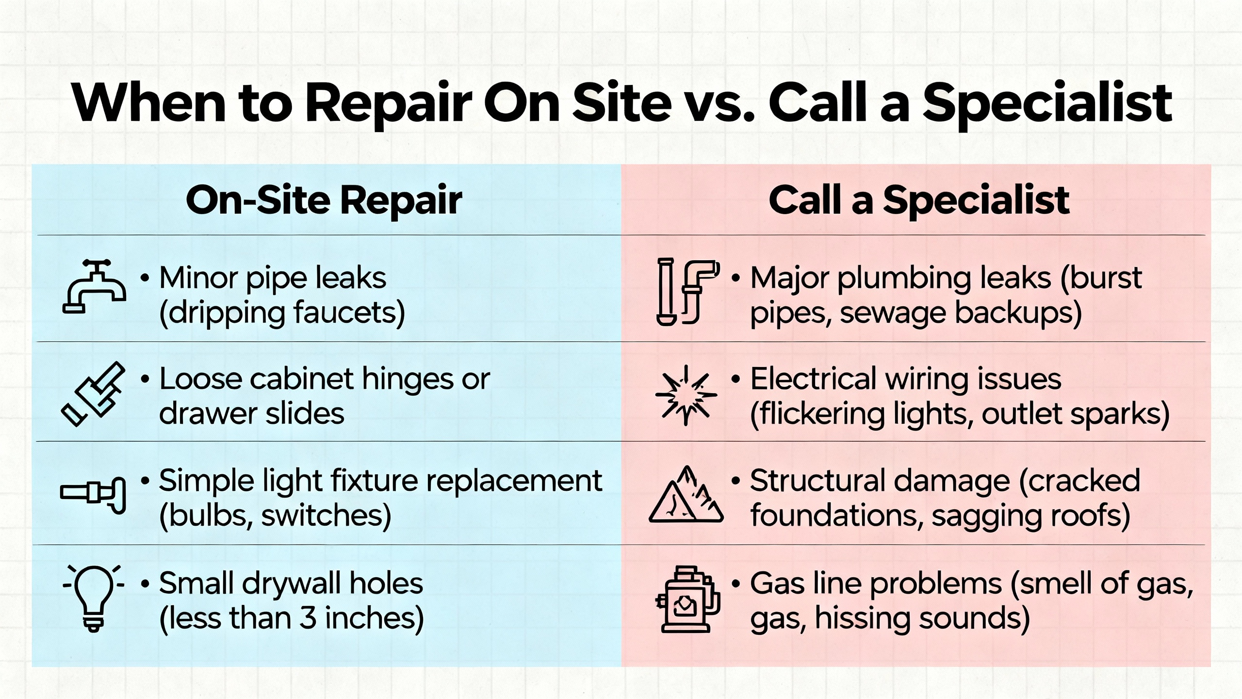
Not every Heidenhain encoder issue needs to go to a repair shop, and not every repair should be attempted on the machine. Knowing where to draw that line saves both time and hardware.
QingongŌĆÖs encoder repair article outlines a typical inŌĆæhouse process: safe removal from the machine, careful disassembly with documentation, inspection for wear, damage, or contamination, cleaning and lubricating mechanical parts where appropriate, replacing damaged nonŌĆæproprietary components, precise reassembly and sealing, and functional testing before reinstallation. For simpler encoders and shops with good electronics experience, this is feasible.
On the machine, inŌĆæhouse teams can almost always handle connector repair, cable replacement, supply voltage correction, and basic cleaning of accessible encoder surfaces according to manufacturer recommendations. YumoelectricŌĆÖs troubleshooting guide emphasizes following the manufacturerŌĆÖs installation, calibration, and maintenance directions and using a multimeter and oscilloscope to confirm basic health.
HeidenhainŌĆÖs ATS software with PWM 20 lets inŌĆæhouse teams do more advanced tasks during installation or repair, such as verifying analog signal quality, adjusting encoder alignment, checking reference marks, and even performing electronic compensation for certain linear encoders. In practice, that moves a large class of ŌĆ£send it out for testŌĆØ tasks onto the shop floor, as long as personnel are trained on the tools.
There are clear cases where the right move is to send the encoder or servo amplifier to a specialist.
Baiza Automation notes that most encoders that initially appear completely dead are actually repairable and can often be addressed economically by a specialized industrial electronics repair center. Cracked housings, broken internal components, severe contamination inside sealed encoders, and catastrophic heat damage are examples where inŌĆæhouse repair is risky or impractical.
ACS Industrial Services specializes in Heidenhain encoder repair and emphasizes that its technicians have access to proprietary technical information and modern diagnostic tools for both minor fixes and major overhauls. They remind customers to supply encoder make and model, specific failing parts, observed symptoms, and any other context when requesting service. That information helps confirm parts availability and minimize turnaround time.
Roc Industrial describes a similar model for both Heidenhain resolvers and servo amplifiers. Their workflow starts with free evaluation and quote, then componentŌĆælevel repair using highŌĆæquality parts, then load testing and quality checks that simulate realŌĆæworld conditions. For servo amplifiers with encoder loss symptoms, this includes verifying that amplifier input stages and feedback processing circuits meet original specifications.
Across these providers, a few patterns emerge. Use a specialist when the failure involves internal mechanics or PCBŌĆælevel damage, when you lack proper diagnostic tools, when downtime costs justify rush repair, or when the encoder remains under warranty or falls under safetyŌĆærelated categories where the manufacturerŌĆÖs safety documentation must be followed closely.
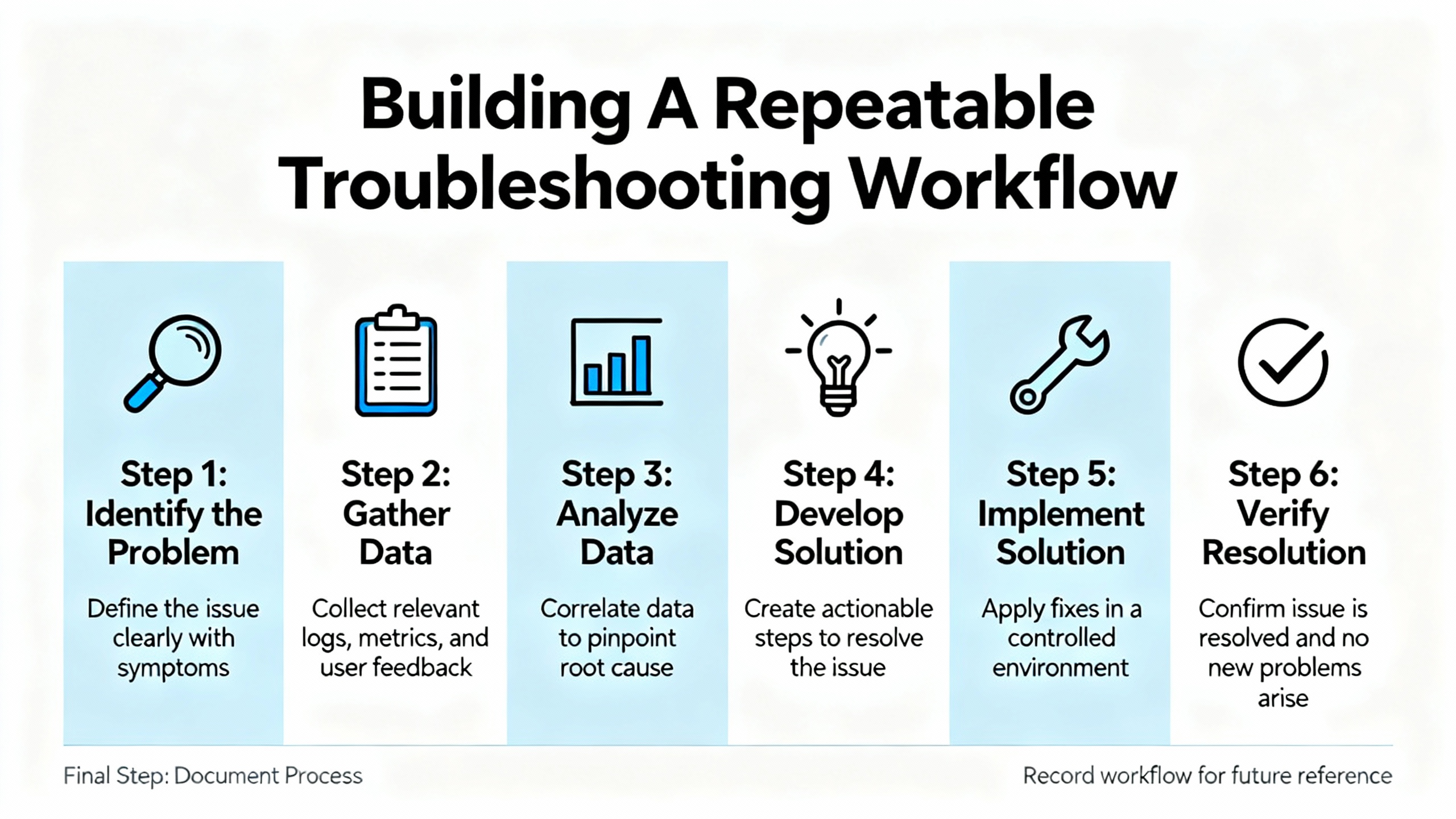
Shops that handle a lot of Heidenhain equipment benefit from turning ad hoc troubleshooting into a repeatable process. The research here, combined with field experience, suggests a practical sequence that balances speed with thoroughness.
A useful workflow begins by capturing the alarm codes and symptoms and checking whether the problem appears only during motion, only at certain speeds, or even at rest. Then it moves through power and basic wiring checks: supply voltage at the encoder, grounding, connector condition, and continuity on all channels between encoder and drive.
Once wiring passes basic checks, it shifts to signalŌĆælevel diagnostics. That can mean a traditional oscilloscope, as suggested by Dynapar and Qingong, or HeidenhainŌĆÖs PWM 20/21 with ATS, which automatically identifies the interface and runs all supported diagnostics. At this stage, you are looking for loss of amplitude, abnormal waveform shapes, clipping, phase errors, or reference marks that do not appear as expected.
If signalŌĆælevel problems are confirmed, the workflow calls for isolating where they originate, using swaps and crossŌĆætests. Swapping in a knownŌĆægood encoder or moving the suspect encoder to a different axis or test fixture can separate encoder faults from drive or interface faults, as recommended by Baiza, Qingong, and Roc Industrial.
Throughout this process, keeping records is important. Qingong advocates maintaining detailed maintenance logs over time. HeidenhainŌĆÖs ATS ŌĆ£ProtocolŌĆØ feature goes further by generating structured reports with encoder ID, interface type, test dates, inspector name, comments, and signal diagrams. Storing those reports with the machineŌĆÖs maintenance records makes future troubleshooting faster and supports quality audits.
Finally, the workflow should end with verification under real operating conditions. ACS stresses testing encoders thoroughly after any repair before returning the machine to production. In practice, that means running axes through typical moves, checking homing and reference marks, and watching for any renewed alarms or position deviations.
Diagnosis is one side of the coin. The other side is design and maintenance choices that reduce the odds of seeing encoder signal loss in the first place.
HeidenhainŌĆÖs own material on optimizing encoder systems and Walker MachineryŌĆÖs tips for digital encoders highlight the importance of selecting the right encoder type for the environment and application. That includes deciding between absolute and incremental encoders, choosing sealed designs for harsh environments, and matching encoder resolution to what the mechanical system can actually deliver. Overspecifying resolution does not overcome backlash or structural compliance and just increases data traffic.
Environmental protection is central. Sealed linear encoders such as the LC series are designed to resist coolant, oil, and dust and operate over wide temperature ranges. For rotary encoders exposed to coolant and chips, choosing models with robust sealing and routing cables through properly rated glands makes a measurable difference in reliability. QingongŌĆÖs and BaizaŌĆÖs emphasis on controlling dust, moisture, and temperature shows that basic housekeeping still matters.
Cabling and grounding practices influence signal quality directly. Multiple sources, including Qingong and Dynapar, advise using shielded cables, correct grounding, and cable lengths within the manufacturerŌĆÖs specifications. Poor shielding or shared conduits with highŌĆæpower lines can contribute to noise that looks like random encoder loss.
Communication interface selection also plays a role. HeidenhainŌĆÖs optimization articles discuss pairing absolute encoders with suitable interfaces, such as EnDat, and note that highŌĆæspeed protocols like EnDat 3 can deliver faster data rates while reducing cabling and simplifying system architecture. Properly matched interfaces not only improve performance but also minimize misreads and communication errors that present as signal loss.
Maintenance routines close the loop. Qingong recommends routine cleaning and inspection of encoders, monitoring signal quality and duty cycle, tightening couplings and mountings, and keeping maintenance logs. Walker Machinery and Heidenhain stress regular scheduled inspection and cleaning to keep scales and optics free of dust, oils, and coolants. Early detection of loose connectors, damaged cables, or creeping contamination can prevent fullŌĆæblown encoder loss faults.
Modern encoders and tools support more advanced strategies as well. Heidenhain describes integrated diagnostics and predictive maintenance features that monitor encoder health in real time and feed into digital twins for simulation and optimization. For highŌĆæend users, leveraging those diagnostics reduces unplanned downtime and improves overall return on investment.
The most reliable method, supported by Baiza Automation and other sources, is to combine basic electrical checks with a knownŌĆægood comparison. Verify supply voltage, continuity, and connector integrity first. Then look at the signals with a scope or Heidenhain test device. If a knownŌĆægood encoder shows clean signals on the same wiring and drive where the suspect encoder fails, the encoder is likely at fault. If both encoders behave the same on that axis but work elsewhere, the drive, interface board, or cabling is the culprit.
For basic diagnosis, a multimeter and oscilloscope are sufficient, as emphasized in QingongŌĆÖs and DynaparŌĆÖs troubleshooting guides. They let you confirm supply, continuity, and signal shape and amplitude. However, HeidenhainŌĆÖs PWM 20/21 with ATS software adds value by automatically recognizing interface types, running manufacturerŌĆæspecific tests, and documenting results in standardized protocols. In a facility that handles many Heidenhain encoders, that can shorten setup and troubleshooting time and provide documentation that a standalone scope cannot.
Once you have ruled out wiring and power issues, and scope or test equipment shows distorted, missing, or outŌĆæofŌĆæspec signals that do not follow wiring or drive swaps, it is time to consider professional repair. Cracked housings, internal contamination, severe thermal damage, or repeated encoder loss faults after basic remedies are additional red flags. At that point, companies like ACS Industrial, Baiza Automation, and Roc Industrial can perform componentŌĆælevel repairs, run full diagnostic protocols, and return units tested to original specifications, often with a warranty.
As an engineer who spends a lot of nights on the floor chasing elusive encoder alarms, I can say that a structured approach pays for itself. Treat Heidenhain encoder signal loss as a system problem, work from simple to complex, use the right diagnostic tools, and lean on reputable repair partners when you hit the limits of what makes sense to do on site. That is how you keep the feedback solid and the machines earning their keep.


Copyright Notice © 2026 mooreautomated.com All rights reserved,Moore Automated is not an authorized distributor or representative of the manufacturers featured on this website. Brand names and trademarks featured are the property of their respective owners.


Leave Your Comment