


MP 3009X
Get A Quote
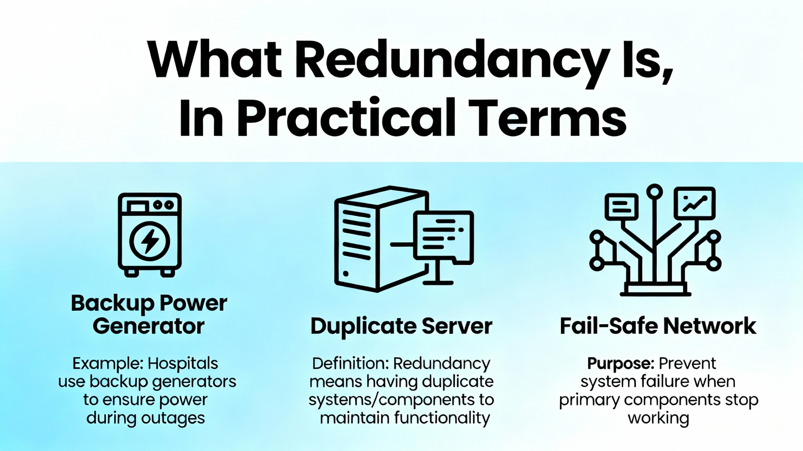
ControlLogix redundancy is a highŌĆæavailability design where a primary and a secondary controller run the same application, stay synchronized over redundant media, and allow a controlled switchover when the primary falters. In practice, most faults in redundant systems trace back to fundamentals: mismatched hardware or firmware between chassis, network configuration mistakes around EtherNet/IP and Device Level Ring behavior, and plain old power and physical layer issues that undermine healthy synchronization. Public sources such as Rockwell Automation manuals for Logix 5590 high availability and the 1756ŌĆæRM2 enhanced redundancy system emphasize using Logix DesignerŌĆÖs redundancy diagnostics to see actual system state and pinpoint where compatibility or health breaks down. FieldŌĆæoriented guidance from Industrial Automation Co, GES Repair, and community threads reinforces that a methodical approachŌĆöstart with build integrity, then network, then power, then logicŌĆösaves the most time.
My onŌĆæsite mindset is simple and pragmatic. I assume redundancy is a strict system. It wants symmetry endŌĆætoŌĆæend, predictable network behavior, clean power, and disciplined change control. When any of those drift, the system tells you in LEDs, status pages, and fault logs. Reading those signals in a structured way is the difference between a clean fiveŌĆæminute switchover test and an extended outage while two identicalŌĆælooking chassis refuse to synchronize.
In a ControlLogix redundancy build, you install identical controllers in separate chassis, match their slot order and module revisions, connect them via redundancy media modules for synchronization, and present I/O over EtherNet/IP or ControlNet such that the field layer runs continuously across a switchover. Industrial Automation CoŌĆÖs guidance stresses enablement in Studio 5000, loading identical logic, and commissioning with deliberate switchover testing before going live. The redundancy modules maintain state and data alignment. The application logic is mirrored. The chassis must be twins in model and layout because the system compares them rigorously.
The benefit is uptime. When the primary controller goes down, the secondary can take over. The tradeoff is complexity, stricter version control, and more to manage on networks and power distribution. Those tradeoffs are manageable with a disciplined build and maintenance routine.
When I step into a redundancy fault, I start in Logix Designer and the hardware, not in the logic editor. I review redundancy status and synchronization health. I compare controller and module firmware on both chassis for an exact match. I check the physical chassis lineup and verify slotŌĆæforŌĆæslot symmetry. I walk the EN2TR or other communication modules to read MS/NS and port LEDs, and if available, I open the module web diagnostics to see Device Level Ring state and any ring faults or role conflicts. I confirm static IP addressing and ensure no duplicate addresses exist across paired chassis. I meter power supplies and verify the 24 VDC rails are within healthy limits, since power issues are a leading cause of controller failures according to GES RepairŌĆÖs field data. Only after these checks do I dig into application events, controller fault logs, and any programŌĆælevel or controllerŌĆælevel fault routines.
This order matters. Redundancy faults frequently boil down to one of three things: the two chassis are not truly identical; the network behaves in a way redundancy did not expect; or the power and environment are marginal and create intermittent behavior that looks like a logic issue.

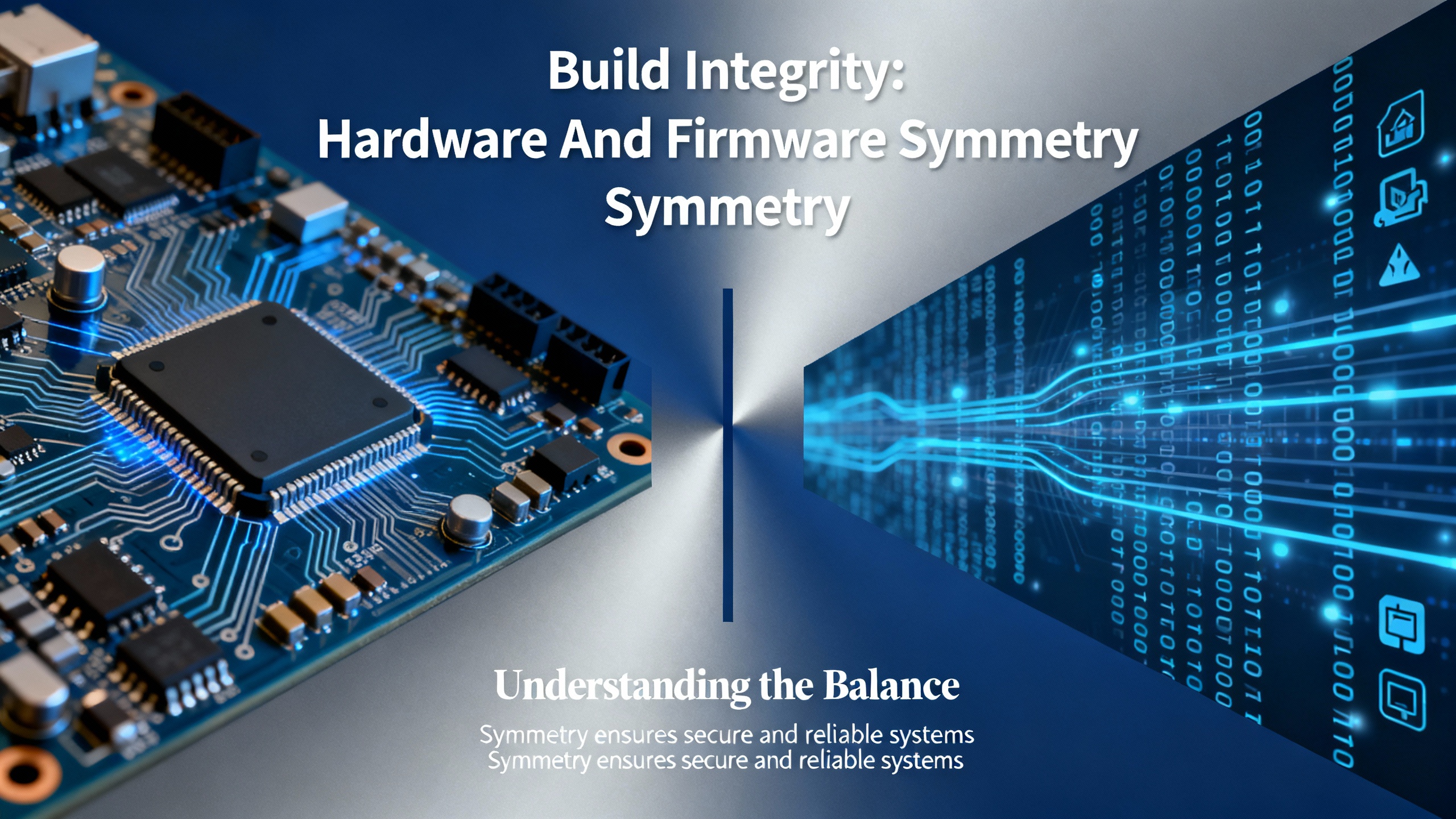
The redundancy pair must be hardware twins. That means the same chassis type, the same power supplies, the same controller family and model line, and the same slot sequence for communication modules and I/O adapters. The Industrial Automation Co material on redundancy calls out matching controller models such as 1756ŌĆæL7x or 1756ŌĆæL8x. The Oxmaint forum summary is blunt about matching not just major but minor firmware revisions for controllers and communications modules, aligned to a supported redundancy bundle. If one EN2TR has a different revision that your chosen redundancy firmware does not support, synchronization trouble is a matter of time.
I validate versions and module revisions with Studio 5000 and ControlFLASH, confirm that both sides are running the exact same bundle, and then perform a second pass with a physical audit. The physical audit catches the one that gets missed when you are rushing: the module that drifted one slot over on a rebuild, or the controller suffix that seemed ŌĆ£close enoughŌĆØ when the spare was pulled from inventory.
The 1756ŌĆæEN2TR is a dualŌĆæport EtherNet/IP module designed for topologies like Device Level Ring. Done right, DLR adds resilience at the device level. Done wrong, it introduces recurring ring faults, duplicate supervision, and connection churn that erodes redundancy stability. The Oxmaint notes define best practice plainly: use static IP addresses across the redundant pair, disable BOOTP, maintain unique addresses per slot in each chassis, and be deliberate about ring supervisor settings so there is only one supervisor where you intend one. The EN2TR LED status and web diagnostics expose MS/NS state, port state, and DLR role in minutes. I read those first.
EtherNet/IP also brings classic pitfalls that mimic redundancy faultsŌĆöa duplicate IP on a spare HMI, a switch replacement that restored power but loaded a different default configuration, or unmanaged switch features interfering with predictable traffic. Industrial Automation CoŌĆÖs network troubleshooting advice applies directly here: verify cabling and terminations, check for congestion or packet anomalies with a packet analyzer when needed, and resolve any IP conflicts immediately. If you are adding produced/consumed tags or additional I/O after commissioning, watch your CIP connection counts and scan class configuration so you do not overload the comms path during switchover.
GES RepairŌĆÖs guidance that a large share of PLC failures tie back to power is a reminder to verify basics. I meter 24 VDC supplies and watch for outŌĆæofŌĆærange rails, loose terminations, and ground faults. I confirm that each redundant chassis has independent, healthy power and that cabinet temperature and ventilation are under control. Heat, dust, and vibration can create intermittent module resets that are indistinguishable from logicŌĆædriven faults when you only read the controller fault line. An infrared scan during scheduled downtime and a simple torque check of terminal screws find problems that logic tools never will.
Periodic tests of network performance and cabinet thermals help build a baseline. When a system has been stable and then starts to wobble, comparing current temperature or error counts to the baseline shortens the rootŌĆæcause path.

Some redundancy faults are controller faults first and redundancy problems second. An application that introduces a periodic task that starves a continuous task, or that accepts an unsafe online edit, will push a controller into a major fault regardless of redundancy. The Electrical Engineering Centre case study illustrates a real fault where a 10 ms periodic task overlapped a continuous task; increasing the period and reviewing execution times resolved the issue and restored stability. Community experience on Control.com surfaces another nuance: concurrent online edits by multiple programmers can provoke crashes and major faults. In practice for redundancy systems, I enforce a oneŌĆæeditorŌĆæatŌĆæaŌĆætime policy, and I serialize acceptance of rung edits. I prefer offline testing or scheduled online windows when a switchover is an unacceptable risk.
When faults do occur, a properly designed fault routine is the lifeline to a safe state and useful diagnostics. PLC Talk discussions highlight controllerŌĆælevel and programŌĆælevel fault handlers in Studio 5000. A good handler captures fault codes and context with GSV instructions, deŌĆæenergizes or parks equipment to a known safe state, and requires an explicit operator acknowledgment to reset. AutoŌĆærestart after a major fault undermines safety and hides root causes. I verify the intended output behavior in faultsŌĆöhold last state versus a defined safe stateŌĆöand make sure the fault routine drives the outputs as designed.

Rockwell Automation manuals for Logix 5590 high availability point first to Logix DesignerŌĆÖs diagnostic views for redundancy. From there, I expand to controller and module fault logs, EN2TR MS/NS LEDs and web diagnostics, and system event logs. The troubleshooting fundamentals from DigiKey TechForum and Control Engineering articles are relevant at this step: know the machine in healthy operation, elaborate symptoms fully before acting, and document everything you observe and change.
I keep a running record of timestamps, LED states, exact fault text, task scan times, and any network changes made in the last shift. Intermittent faults often become solvable when you can line up a controller log entry with a ring role change on the EN2TR and a recorded temperature spike. That context turns guesswork into a root cause.

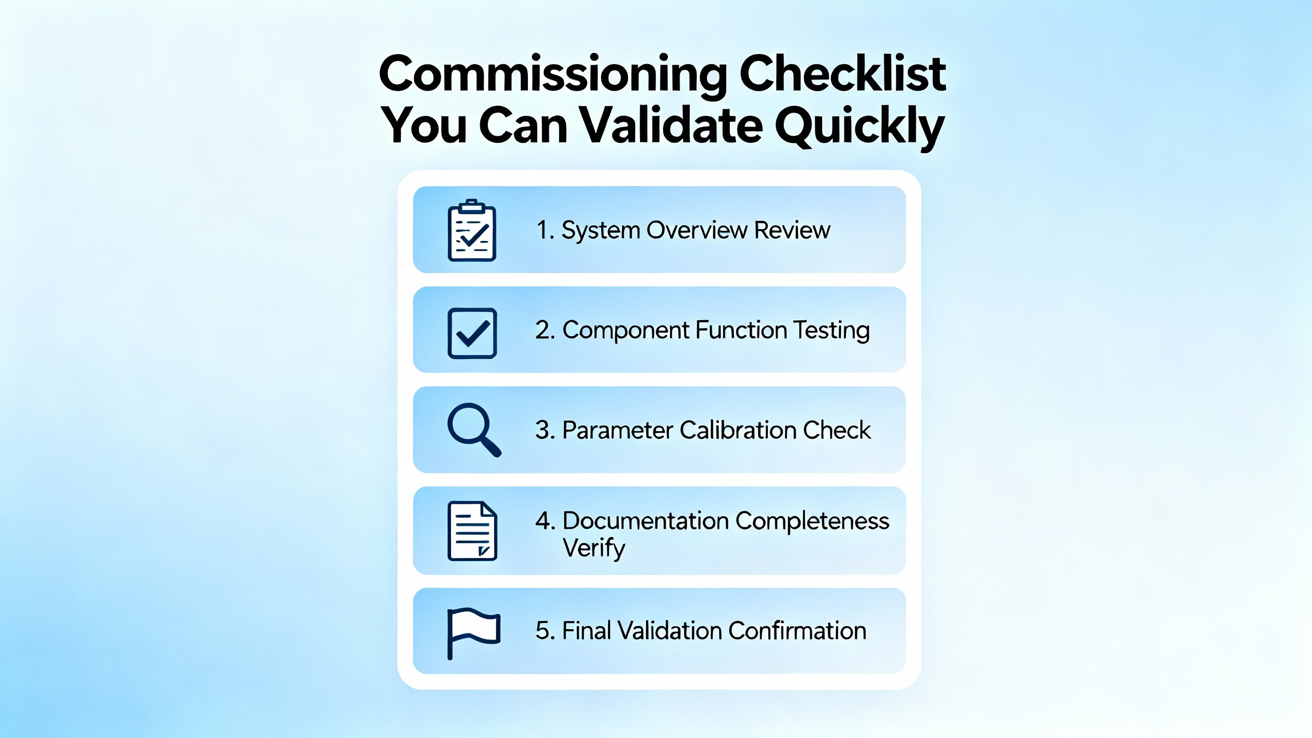
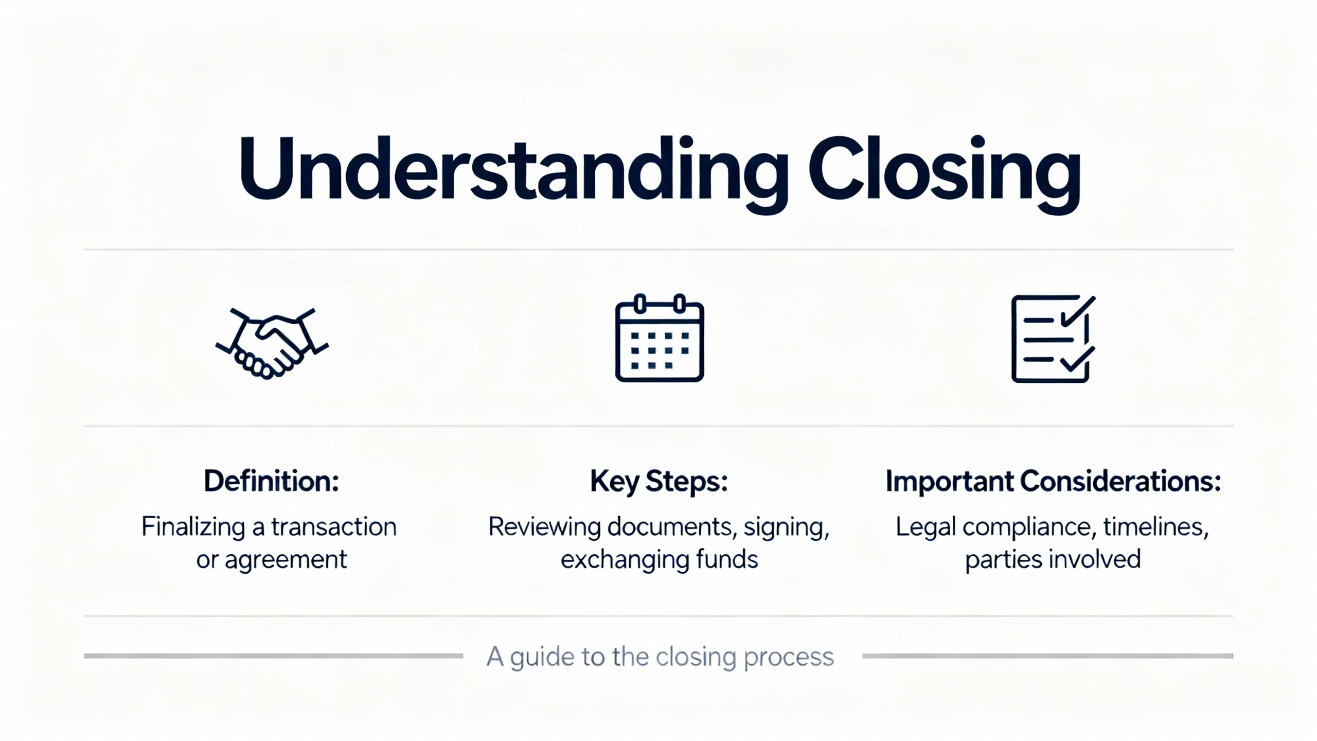
Commissioning is not complete until you have tested redundancy switchover in a controlled, safe scenario. Guidance from Industrial Automation Co emphasizes simulating a primary controller fault and observing a seamless takeover before goŌĆælive. I structure a test that matches actual operating conditions as closely as possible, verify that the process holds state as required, watch I/O connection health across the switchover, and capture log data to set a baseline for future comparisons. If the test is not seamless, I backtrack to symmetry, network, and power checks until it is.
After commissioning, I schedule regular failover exercises during planned downtime. This keeps muscles fresh and reveals silent regressions, like a reactor of firmware drift or an unintended change to a switch that only shows up during a switchover.

To accelerate triage, I map visible symptoms to likely causes and the first check I perform. The entries below are grounded in the issues called out by Industrial Automation Co, Oxmaint, GES Repair, and community discussions.
| Symptom at the Panel or in Logix | Likely Cause in a Redundant Build | First Checks That Pay Off |
|---|---|---|
| Redundancy not synchronizing or frequent resyncs | Asymmetric slot order or unsupported module revision across chassis | Compare module order and revisions sideŌĆæbyŌĆæside; verify against supported redundancy bundle in Rockwell documentation |
| EN2TR MS/NS flashing red or ring alarms | DLR misconfiguration, duplicate ring supervisors, or duplicate IPs | Read EN2TR web diagnostics; confirm single supervisor where intended; audit static IP assignments and disable BOOTP |
| Unexpected switchover under load | Power rail dips, cabinet heat, or congestion on EtherNet/IP | Meter 24 VDC under load; check cabinet temperature and ventilation; baseline and compare network error counters |
| Major fault after an online edit | Concurrent edits or unsafe change to task timing | Enforce oneŌĆæeditor access; review task execution times; stage changes offline when feasible |
| Produced/consumed tags drop during switchover | Connection count saturation or misrouted paths | Review CIP connection counts and paths; adjust RPI or topology to keep margins during takeover |
| Controller stuck in Program or not resuming | Startup configuration or safety interlock logic | Inspect Startup settings; validate fault routines and interlocks; require operator acknowledgment for reset |
Redundancy earns its keep in continuous process environments because it minimizes unplanned downtime and provides a structured way to absorb a controller failure. It also raises the bar for discipline. The build must be symmetrical in hardware and firmware. The network must be predictable with deliberate DLR roles and stable IP assignments. The power environment must be clean. The downside is that misalignment in any of these areas leads to more complex faults than a singleŌĆæcontroller system, and that commissioning is incomplete until switchover behavior is proven under realistic conditions.
The most durable redundancy systems are built and maintained with a few consistent habits. I maintain an exact inventory for each chassis with model and firmware, and I treat firmware as a bundle tied to redundancy support notes rather than as a casual update. I use static addressing everywhere that touches redundancy and take the time to document subnet and gateway settings for each slot. I verify ring supervision deliberately, making sure the EN2TR roles are set intentionally and not left to chance. I keep power rails healthy and separate where possible for the two chassis, and I enforce cabinet cleanliness and cooling. I schedule quarterly checks of network performance and quick thermal scans of panels because those two activities catch power and heat trends early. I use Studio 5000 diagnostics proactively and keep controller fault routines simple, safe, and wellŌĆætested. I maintain backups and version control, leveraging tools like AssetCentre where appropriate, so that rollback is fast and clean when a change introduces instability.
Even though redundancy is an availability feature, it does not exempt you from the basics of industrial cybersecurity and change management. Guidance from CTI Electric highlights strong access controls, tight control over removable media, and offline, tested backups. I also enforce a singleŌĆæeditor rule for online changes and treat vendor firmware and software updates as controlled events. Redundancy adds moving parts; an unreviewed change to a switch, a casual firmware update on one chassis, or an external actor with weak credentials can destabilize the system as surely as a loose terminal screw.
When internal efforts stall and you need to engage Rockwell TechConnect or a trusted partner, the quality of your evidence speeds resolution. I capture the redundancy status from Logix Designer at the time of the fault, controller and module fault logs with timestamps, EN2TR diagnostic screenshots including DLR state, CIP connection counts if relevant, measured power rail values, cabinet temperature at the time, and a change log covering the previous day. Industrial Automation Co recommends keeping firmware and Studio 5000 current, but that advice comes with a precision caveat: update in pairs and within supported redundancy bundles, not one chassis at a time.
A redundancy build that passes the following quick checks is much less likely to surprise you during a switchover. Each item maps to issues emphasized by Rockwell documentation and the industry guidance summarized earlier.
| Item | Requirement | Why It Matters |
|---|---|---|
| Controllers and chassis | Identical controller family and model; identical chassis type | Redundancy compares chassis strictly; model mismatches break sync |
| Slot order and modules | SlotŌĆæforŌĆæslot identical modules and positions | Synchronization expects a mirrored hardware map |
| Firmware bundle | Exact matching major and minor revisions across controllers and comm modules | Redundancy support is versionŌĆæbundled; minor drifts can be fatal |
| IP addressing | Static IPs; unique per slot across both chassis; consistent subnet/gateway | Duplicate IPs and inconsistent networks cause intermittent dropouts |
| DLR configuration | Single, deliberate ring supervisor; coherent DLR roles | Multiple supervisors or undefined roles create ring instability |
| Power and environment | Healthy 24 VDC rails, clean cabinets, adequate cooling | Power dips and heat lead to intermittent resets and sync loss |
| Fault handling | Controller and program fault routines tested endŌĆætoŌĆæend | Safe recovery and useful diagnostics depend on these paths |
| Switchover test | Controlled failover under realistic load with logs captured | Commissioning is incomplete until the takeover is proven |
What should I check first when redundancy refuses to synchronize even though the logic matches? Treat it as a hardware and firmware symmetry problem before a logic problem. Compare module order and revisions lineŌĆæbyŌĆæline, verify both controllers and communication modules are on the same supported redundancy bundle per Rockwell, and confirm static IP and DLR roles are consistent.
Do I need Device Level Ring to use redundancy on EtherNet/IP? No. Redundancy can run over EtherNet/IP without DLR, but if you do use DLR on EN2TR modules, be deliberate about ring supervision and IP hygiene. Misconfigured DLR is a frequent source of intermittent faults.
Is there a rule of thumb for editing online on a redundant system? Yes. Use one editor at a time, serialize rung acceptances, and prefer staging significant changes offline. Community experience shows concurrent online edits can trigger faults that have nothing to do with redundancy.
Redundancy earns its keep when the small, disciplined things are done rightŌĆömirror the hardware and firmware, make the network boring and predictable, keep power clean, and test the takeover before you need it. When a fault does land, read what the system tells you, capture the evidence, and work the basics in order. ThatŌĆÖs how you turn a flashing LED into a confident switchover instead of a long night at the panel.


Copyright Notice © 2026 mooreautomated.com All rights reserved,Moore Automated is not an authorized distributor or representative of the manufacturers featured on this website. Brand names and trademarks featured are the property of their respective owners.


Leave Your Comment