


MP 3009X
Get A Quote
As an onŌĆæsite automation engineer, I judge every troubleshooting minute by its impact on production. AllenŌĆæBradley platforms such as ControlLogix, CompactLogix, and MicroLogix are resilient, but when they fault, the difference between a fiveŌĆæminute reset and a fiveŌĆæhour outage is a disciplined method, the right measurements at the right time, and a clear understanding of what the controller is really telling you. This field manual consolidates proven practices from shop floors and training rooms into a single, practical guide. The goal is simple: reduce downtime while improving safety, confidence, and longŌĆæterm reliability.
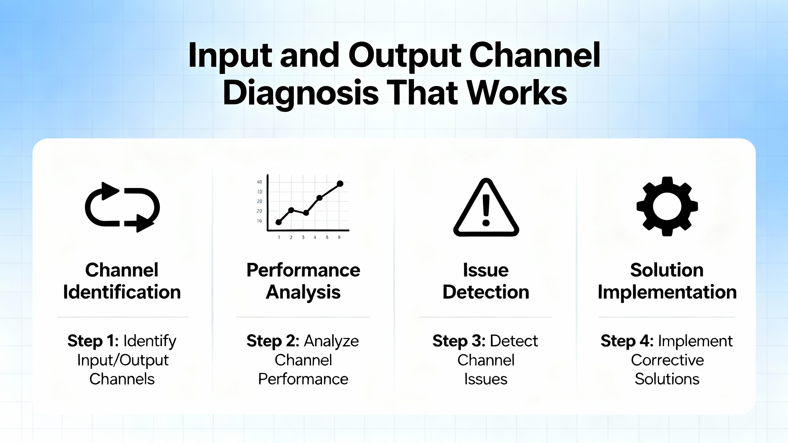
Effective diagnosis begins with safety and structure. Lock Out Tag Out, adherence to OSHA rules, jobŌĆæspecific PPE, and a deliberate buddy system are nonŌĆænegotiable. Even seemingly benign control panels can present lethal hazards once doors open and interlocks are defeated. DigiŌĆæKey TechForum emphasizes that troubleshooting is a teachable skill when approached systematically, not a mysterious talent. A simple, consistent procedureŌĆörecognize symptoms, elaborate them, list probable faulty functions, localize the faulty function, isolate to the circuit, and complete failure analysis with documentationŌĆöprevents tunnel vision and protects your credibility when minutes matter.
A culture of written Standard Operating Procedures helps tremendously. Use machineŌĆæspecific SOPs for startŌĆæup, running, and shutŌĆædown while keeping machine logbooks current. Record the initial complaint, each test, measured values, the fix, and the root cause. Those notes will save hours the next time a temperatureŌĆædependent or intermittent fault returns two months later on a night shift.

Most failures trace to familiar domains. Electrical integrity is the baseline; surges, sags, missing neutrals, poor grounding, and blown power supplies are usual suspects. Environment erodes reliability through heat, dust, and vibration; cracked terminals and fatigueŌĆæloosened fasteners take systems down during production peaks. Software problemsŌĆöcorrupted files, logic regressions, or version incompatibilityŌĆöare common when updates and backups fall behind. Components wear out: fans clog, connectors oxidize, batteries expire. Networks drop due to duplicate IPs, congested switches, or damaged cables. Human error remains a factor; incorrect inputs, accidental program edits, or rushed panel work introduce new faults more often than anyone likes to admit. These themes recur across independent summaries from Industrial Automation Co., AES, and training materials referenced in DigiŌĆæKeyŌĆÖs guidance.
Fast triage prevents days of chasing phantoms. Start with what the system shows you. Module face LEDs and CPU indicators tell you if power and logic agree. Electrical Engineering Portal notes that on input modules, a power LED indicates the field device is energized, while a logic LED indicates the module logic actually recognized the signal. If power is present and logic is absent, suspect the module. Outputs behave similarly; a logic LED indicates the command reached the module, while a power indicator or fuse indicator reveals whether the output side is energized or blown. When LEDs disagree, localize the problem around the module and verify fusing and current limits before moving on.
LEDs are invaluable but not infallible. DigiŌĆæKey TechForum cautions that fast signals do not display reliably on frontŌĆæpanel LEDs, so avoid conclusions about pulse trains or highŌĆæfrequency events based on slowŌĆæupdating indicators alone. When in doubt, measure.
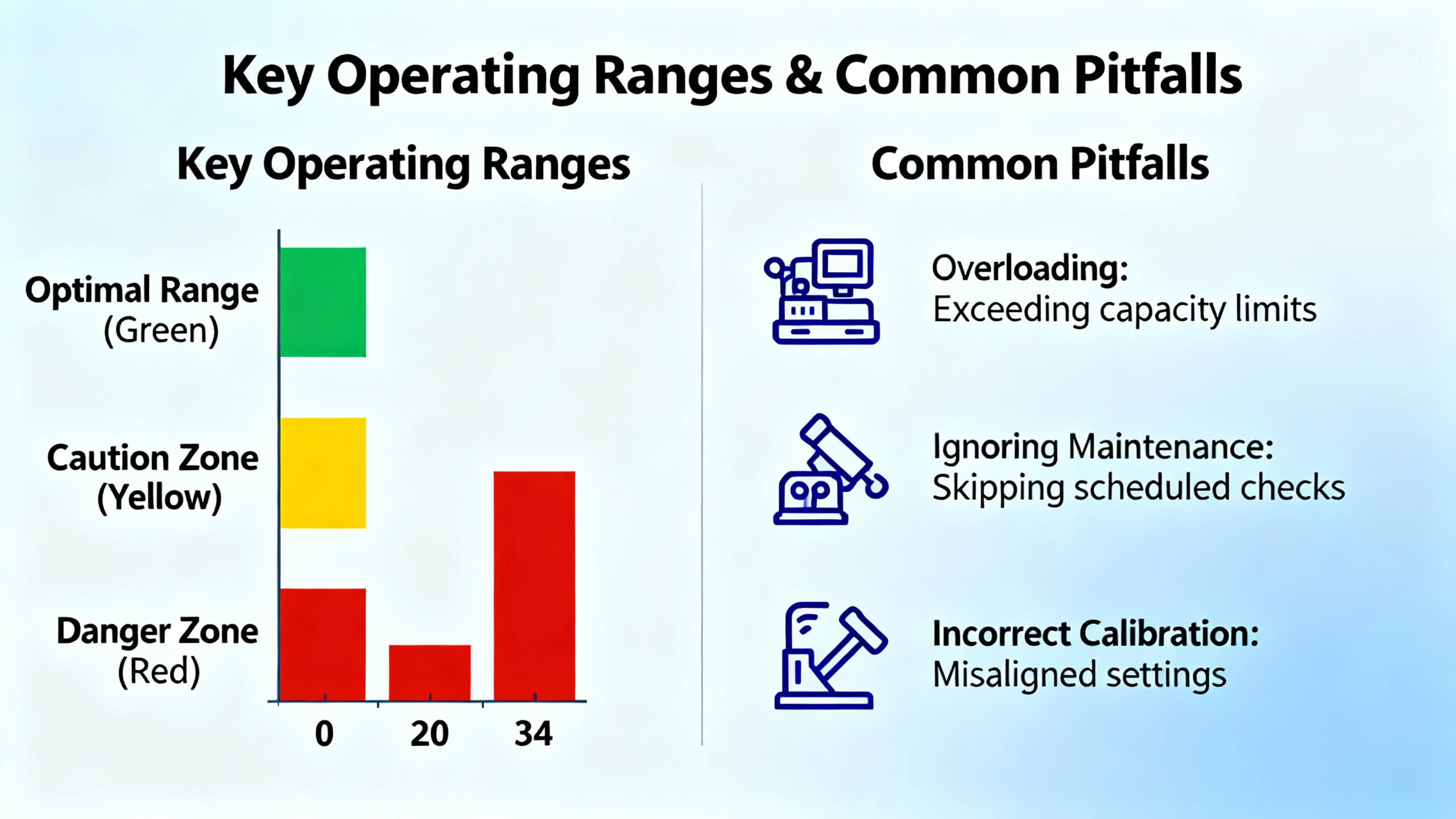
For discrete I/O at 120 VAC, verify the supply remains within about 108ŌĆō132 VAC during loading, as EEPŌĆÖs troubleshooting notes recommend. On DC I/O and analogs, measure at the terminal under actual operating conditions and confirm the return path is intact; many ŌĆ£mysteryŌĆØ analog drifts resolve when a loose return lands correctly. When an output is ŌĆ£ONŌĆØ in logic but the field device is idle, measure at the output terminal and at the device. Voltage at the terminal with no response from the device points to wiring or a failed actuator, while no voltage at the terminal indicates a failed output channel or blown fuse.
FieldŌĆætested input diagnosis follows a deliberate rhythm. Place the controller in a nonŌĆæoutput test or standby mode to prevent unintended motion, then actuate the field device by hand. If the moduleŌĆÖs power indicator turns on, wiring continuity is likely intact. Confirm that the controller sees the change in its input image or that the ladder contact highlights in the programming software. If the field voltage is present but the logic image never updates, the input channel or its optoŌĆæisolation may be compromised, and the module should be replaced. If the measured voltage is significantly below nominal at the module during activation, suspect the source feeding the switch. If the module reads nothing and no voltage is present at the field device, trace wiring, terminations, and the field device itself until you restore continuity.
Output testing mirrors that method. Confirm the processor command is present by watching the moduleŌĆÖs logic indicator, then measure the output terminal to ensure the switching device is actually providing power. If terminal voltage is healthy yet the device is dead, work outward into wiring, connectors, and the device. When fuses blow repeatedly, suppress inductive loads and confirm that the outputŌĆÖs current limits fit the application. EEPŌĆÖs guidance is blunt on this point: modules failing in cycles typically point to unsuppressed inductive spikes or overcurrent.
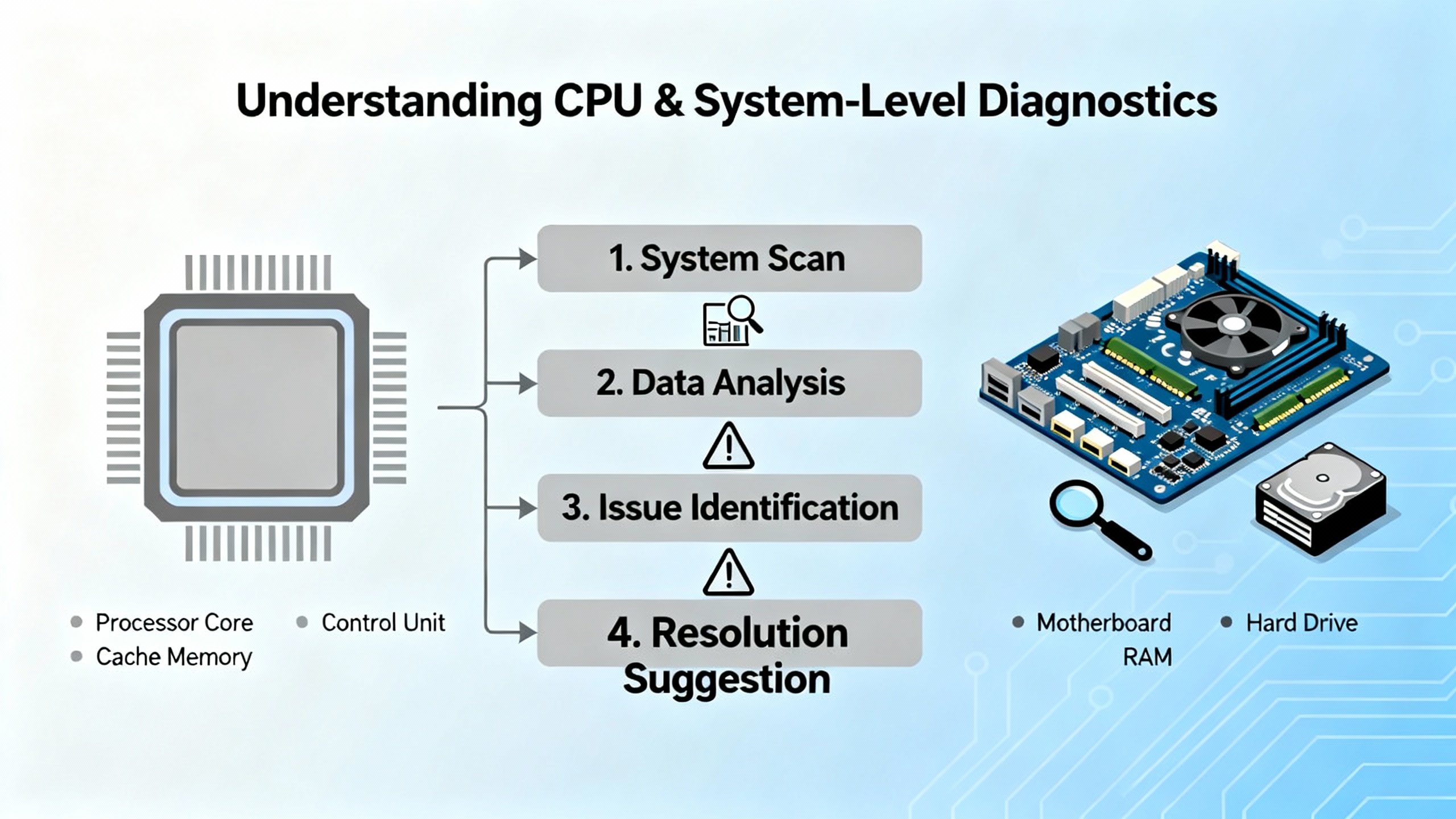
Controller front panels and software diagnostics provide a second layer of insight. PowerŌĆæOK, memoryŌĆæOK, and communicationsŌĆæOK indicators quickly narrow your search to supply, program integrity, or network. If correct power is verified at the controller and the machine remains down, expect a CPUŌĆælevel issue. Review the controllerŌĆÖs fault history, LED patterns, and any subcodes. Watch for voltage drops at the control transformer, loose fusing, and heatŌĆæstress in the cabinet. General references from AES and DigiŌĆæKey both stress that systematic power checks and a glance at the history buffer often distinguish a fifteenŌĆæminute reset from a day of disassembly.
When a Logix controller raises a fault, the hexadecimal codes are not random; they point to families of issues. Global Electronic Services provides a useful crossŌĆæsection of codes and actions that aligns with field experience across ControlLogix and CompactLogix.
| Code (hex) | Category | PlainŌĆæEnglish meaning | First actions that matter |
|---|---|---|---|
| 0x04 | Program execution | Recoverable logic fault such as divideŌĆæbyŌĆæzero stopping execution | Inspect recent changes, review the rung where execution halted, correct logic, and restart with care |
| 0x08 | Watchdog | Scan ran too long; logic exceeded the watchdog | Optimize heavy routines, eliminate runaway loops, and consider scheduling or a faster CPU if justified |
| 0x0F | Memory nonrecoverable | Serious memory problem | Attempt firmware reflash; be prepared for controller replacement if integrity cannot be restored |
| 0x300 | Insufficient memory | Controller out of space | Remove unused routines, data, and trends; optimize structures and retentive tags |
| 0x320 | Program corruption | Application integrity compromised | Reload from a verified backup and validate all I/O and comms paths before resuming operation |
| 0x12 | I/O timeout | Processor lost contact with a module | Check cables, connectors, backplane seating, and remote I/O links |
| 0x80 | EtherNet/IP timeout | Network path exceeded timeouts | Investigate switch health, congestion, duplex/speed settings, and cable quality |
| 0x88 | Duplicate IP | Conflicting IP addresses on the network | Resolve address conflicts and document addressing to prevent recurrence |
| 0x1F | Config mismatch | Module configuration doesnŌĆÖt match controller | Reconcile module profiles after firmware updates or replacements |
| 0x81 | CIP connection failed | Requested connection could not establish | Validate connection parameters, routes, and device state |
| 0x700 | Motion axis fault | Drive/axis fault demands immediate attention | Check feedback, wiring, and mechanical binding before any retune |
| 0x730 | Excessive position error | Axis cannot hold commanded position | Inspect mechanics and tuning; correct backlash, coupling slip, or load issues |
The codes are directional, not definitive. The fix still requires isolation, measurement, and confirmation. Always capture the exact code and subcodes in your log before clearing anything.
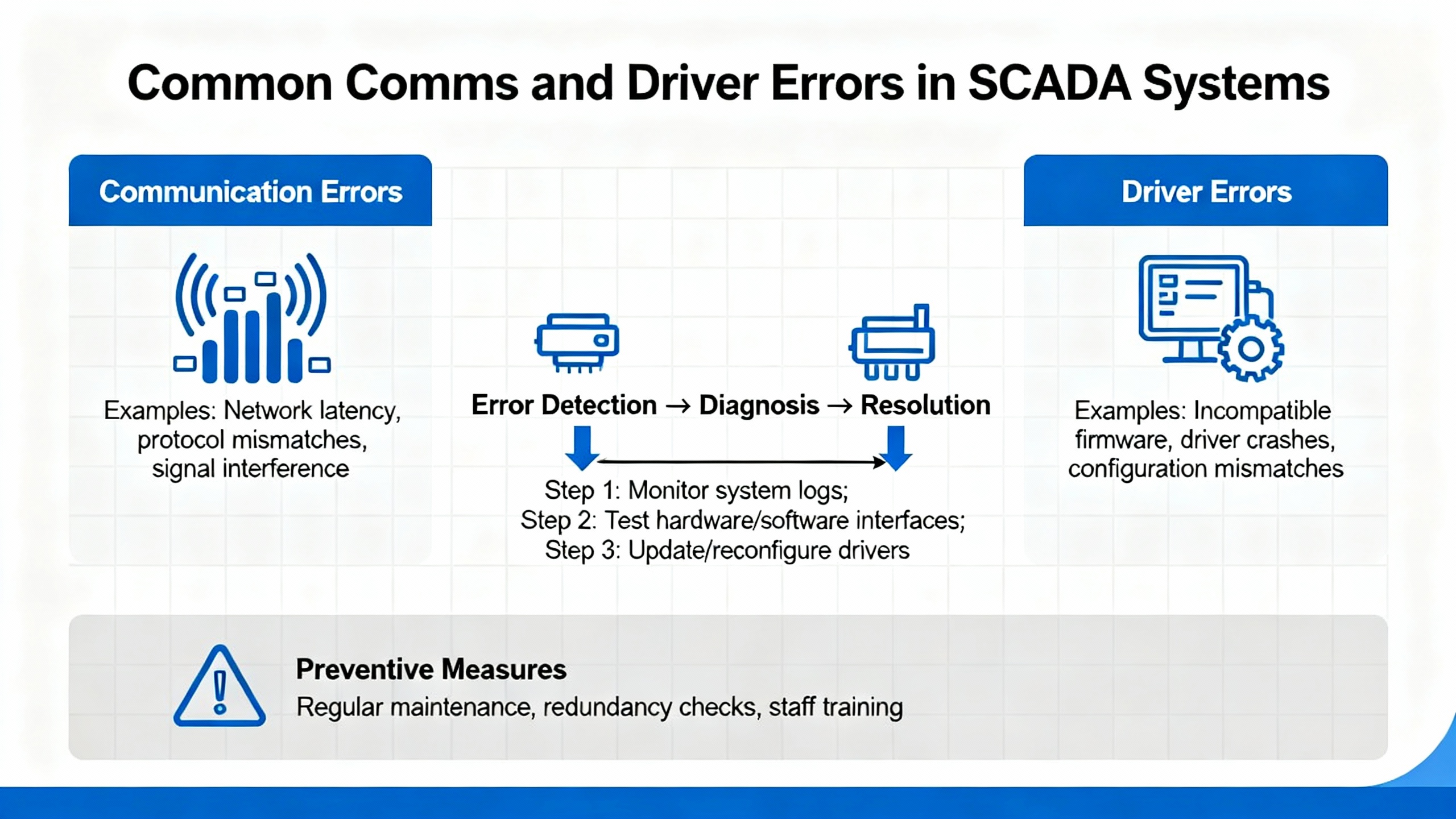
At the SCADA/driver layer, error numbers describe transport and addressing issues that masquerade as PLC faults. VTScadaŌĆÖs AllenŌĆæBradley driver documentation is concise and useful for crossŌĆætraining operators. Representative problems include program mode indications when a controller is not executing logic, illegal address or symbol not found whenever a tag path is wrong or an EDS is missing, retry limits exceeded and response timeouts when a link is noisy or congested, and socket establish or lost socket errors when the TCP path is broken or a firewall intervenes.
| Driver code (decimal) | Symptom | Likely cause | Where to look first |
|---|---|---|---|
| 112 | Processor in Program Mode | Controller not executing logic | Confirm keyswitch or remote mode, clear underlying faults before RUN |
| 513 | Illegal address | Bad tag/file reference | Validate path, file sizes, and ranges in the project |
| 260 | Symbol not found | Name does not resolve | Confirm tag exists and is spelled as deployed |
| 553 | Bad BCC/CRC | Checksum failed | Check line noise, shielding, and protocol settings |
| 512 / 551 / 773 | Retry limit or timeouts | Congested or noisy link | Inspect cabling, terminations, and switch health |
| 768 / 772 | Socket establishment or lost connection | TCP path broken | Verify IP/port, VLAN/ACLs, and device power |
Translating driver codes into operatorŌĆæfriendly alarm messages prevents false escalations. When a historian shows dozens of 773 timeouts around shift change, for example, the fix may be at a saturated switch rather than an ŌĆ£unreliable PLC.ŌĆØ
Analog drift and phantom inputs often trace to grounding. EEPŌĆÖs troubleshooting guidance shows how shielded cable grounded at both ends creates a current path between chassis grounds at different potentials. That loop current induces magnetic fields into your signal reference and corrupts the measurement. The practical fix is to connect the cable shield to ground at one end onlyŌĆöpreferably at the PLC or analog input card. To check for loops, disconnect the shield at its termination and measure resistance from wire to termination. A high resistance suggests no parallel path; a low reading reveals continuity and at least one loop. Correcting shield terminations, verifying singleŌĆæpoint grounds, and rerouting noisy conductors away from sensitive signals stabilizes analogs without rewriting a single rung.
A PLC ŌĆ£heartbeatŌĆØ bit is an inexpensive sentinel for health, comms, and logic progression. The Inductive Automation community offers a pragmatic pattern: toggle a bit in the controller every second when healthy, then use an Ignition expression such as hasChanged on the heartbeat tag to alarm when it stops changing. Assign the tag to a clock scan class aligned with the heartbeat rate and add a short timeout to avoid nuisance alarms. This catchŌĆæall detects major and minor PLC faults as well as network problems and reconnect cycles. Pair the heartbeat with device status and driver error codes to differentiate logic halts from comms losses, and link the alarms to a clear operator guide so the first response matches the failure mode. Inside the PLC, the builtŌĆæin watchdog backs you up by halting scan on runaway logic and forcing a clear diagnosis rather than silent misbehavior.
The cheapest fault is the one that never happens. Hale Engineering & Consultancy Services recommends staying current on firmware and software with a staged, nonŌĆæcritical test before production rollout. Field cases exist where phantom analog input faults disappeared after applying a Rockwell update that had been available for months. Environmental inspections reduce stress: verify airflow, remove dust with antiŌĆæstatic methods, and inspect terminations and mounting for looseness or corrosion. Memory usage and scan time trends, power cycle counts, and EtherNet/IP diagnostics should be reviewed regularly in Studio 5000 or FactoryTalk Diagnostics to catch degradation before it trips production. Training and documentation multiply your coverage; clear tag naming, change logs, and standard recovery playbooks cut resolution time for junior techs.
Backups and restore drills are nonŌĆæoptional. PLC Department outlines a robust approach: upload knownŌĆægood programs after changes, keep versionŌĆæaccurate software on a service laptop, mirror backups on secure onŌĆæsite and offŌĆæsite storage, and periodically test restores on spare hardware. SD cards, where supported, provide a fast onŌĆædevice fallback, but you still need a recent file and a plan. Version control adds discipline to changes you canŌĆÖt afford to lose. Cybersecurity around backups matters; access control and encryption pay for themselves the first time a critical program is protected from tampering.
Design choices either ease or obstruct future diagnosis. PLCskilltree highlights modular, UDTŌĆæbased architectures that enable fast isolation without spelunking a monolith. Shallow function nesting, descriptive tags, and crossŌĆæreferenceŌĆæfriendly read/write locations help engineers answer the only question operators care about: why that actuator didnŌĆÖt move when commanded. Document block purposes and sequence notes inside the code and remove dead test logic so surprises remain rare.
A thoughtŌĆæout inventory turns a long outage into a planned pause. Electrical Engineering Portal recommends a practical rule of thumb: hold roughly ten percent of commonly used parts, keep one spare for each main CPU board and each power supply, and consider a full spare rack for missionŌĆæcritical systems where diagnosis time is a luxury you donŌĆÖt have. Stock fuses, relays, network switches with known configurations, tested patch cords, and battery kits appropriate to the controller family. Favor authorized distributors for controllers, motion modules, and safety components to avoid compatibility and warranty issues, and label every box with firmware levels where relevant.
Care extends to power quality and protective gear. Use UPS units sized for your loads and confirm neutral and ground integrity. In panels feeding hazardous equipment, moldedŌĆæcase breakers with shunt trip coils make remote emergency isolation possible; that capability enhances safety and complements EŌĆæStops when seconds count, a point raised by industry practitioners on professional networks. Finally, if you are considering refurbished parts, apply them to nonŌĆæsafety roles first, validate under load, and document any performance differences. The value is real, but risk tolerance differs by plant and process.
An intermittent analog misread that trips a highŌĆætemperature alarm once every few hours is a classic production nuisance. A quick pass at the panel might show a stable power LED on the input module but an analog value that jitters. Toggling the physical shield at the transmitter reveals a quiet signal for minutes, then noise returns. Measuring resistance between the cable shield and the remote chassis after disconnecting at the PLC shows low ohms and confirms a ground loop. Moving the shield termination to the PLC side only, dressing the cable away from a VFD feeder, and confirming the loop resistance is now high restores a stable signal. The operatorŌĆÖs log is updated, the cause is recorded as ŌĆ£loop current via dualŌĆæended shield,ŌĆØ and a short line is added to the SOP so future expansions keep shield terminations consistent. The fix took less than an hour on a busy morning, and the alarm point has been quiet since.
A different day brings a stopped conveyor after lunch with a ŌĆ£Major FaultŌĆØ banner on the HMI. The CPUŌĆÖs status shows a 0x04 recoverable fault on a recently modified routine. Reviewing the rung reveals a divideŌĆæbyŌĆæzero that occurs when a sensor goes offline during a scheduled cleaning. The logic is patched to prevent division when the sensor quality flag is bad, the routine passes verification, the controller is restarted into RUN, and the log captures the code and the preventative change. Downtime stays measured in minutes rather than hours because the team checked the fault history before flipping switches.
The right instrumentation accelerates root cause. A digital multimeter for voltages and continuity tests, a network cable tester for suspect comms, a laptop with current programming software and drivers, and a thermal camera for hotŌĆæspot hunting are worth carrying daily. In software, use trends and logs to correlate alarms with load, temperature, or shifts. When a watchdog fault appears near the end of a heavy batch, long loops in a user routine might be the real culprit. Keep your ticketing or CMMS aligned with these observations; patterns emerge only when data is captured consistently.
Trustworthy alarms align with how systems fail. A heartbeatŌĆæbased monitor for ŌĆ£PLC not updatingŌĆØ combined with deviceŌĆælevel status produces actionable events rather than ŌĆ£PLC badŌĆØ spam. Add short confirmation delays to avoid transient comms blips, and group driver timeouts separately from logic faults so the first responder knows whether to inspect switches or open the controller project. Use clear operator messages tied to the fault code families in this manual, and guide the next action: measure voltage at terminal X, verify the moduleŌĆÖs logic LED against power LED, or check the controller mode.
A handful of numeric anchors resolve many disputes. On 120 VAC control circuits, expect voltage to live between roughly 108 and 132 VAC under load. If an input flags ŌĆ£ONŌĆØ only when the meter shows 135 VAC because a transformerŌĆÖs tap was misŌĆæset, the next brownout will bring intermittent failures. When LEDs disagreeŌĆölogic ŌĆ£ONŌĆØ and power ŌĆ£OFFŌĆØ or vice versaŌĆöthe module is either damaged or the field wiring is misapplied. Blown fuses that return within hours frequently point to inductive loads without suppression or to devices drawing beyond the channelŌĆÖs rating. Duplicate IP addresses rarely announce themselves politely; they appear as random communication losses at shift start when somebody powers on a spare panel with a factoryŌĆædefault address.
Reliable AllenŌĆæBradley troubleshooting blends disciplined process with simple measurements. Begin with safety and a structured method, use indicators to aim your first tests, confirm with a meter under real load, and let fault codes guide your search rather than dictate it. Maintain firmware and backups, train technicians on SOPs and tag conventions, design programs for visibility, and stock the spares that truly shorten outages. Most importantly, record what you find. TodayŌĆÖs fix is tomorrowŌĆÖs fiveŌĆæminute save for someone on your team.
Q: How do I tell a communications drop from a controller lockup when both look like ŌĆ£no dataŌĆØ on the HMI? A: Combine a PLC heartbeat bit with SCADA driver status and driver error codes. If the heartbeat stops and driver errors show socket or timeout problems, suspect the network path. If the driver shows healthy status while the heartbeat is frozen, suspect a logic halt or Program Mode at the controller. This separation focuses the first check on either switches and cables or on the controller and its fault history.
Q: What should I check first when a Major Fault stops the line? A: Read and record the exact code and any subcodes before clearing anything. Recoverable execution faults such as 0x04 often point to a specific rung; nonrecoverable memory faults like 0x0F push you toward firmware recovery or replacement. Review the fault history in Studio 5000 and confirm controller mode and I/O power before making logic changes.
Q: When should I replace a module versus keep chasing wiring? A: Let the indicators and a voltage reading decide. If an input channel shows proper field voltage at the terminal while the logic LED never registers, replace the module. If an output shows the logic LED on and no voltage at the terminal with a good fuse, replace the module. If terminal voltage is correct but the device remains inactive, keep tracing wiring and the device itself.
Q: How often should I perform maintenance on AB PLCs? A: A pragmatic cadence is to review firmware and diagnostics quarterly, conduct environmental and hardware inspections at least twice per year, and run a professional health check annually. Weekly quick visual checks catch many issues early. The interval tightens for harsh environments or critical processes.
Q: What spares are worth holding on site? A: Maintain roughly ten percent of frequently used parts, at least one spare main CPU and one spare power supply, and the fuses and relays that most often fail. For timeŌĆæcritical operations where diagnosis time is limited, a spare CPU rack can be justified. Keep network switches, patch cords, and labeled SD cards or backups ready.
Q: Can I hotŌĆæswap I/O modules? A: Some systems permit hotŌĆæswap, others require power down. Verify the specific module and chassis capability in Rockwell documentation before attempting. When in doubt, schedule a safe stop and power down to protect equipment and personnel.
The practical methods summarized here align with tutorials and case notes from Electrical Engineering Portal on LEDŌĆæguided I/O diagnosis and grounding practice, DigiŌĆæKey TechForum for structured NavyŌĆæstyle troubleshooting and safety, Global Electronic Services on fault code families in ControlLogix and CompactLogix, Industrial Automation Co. on maintenance cadence and common errors, Hale Engineering & Consultancy Services on firmware and health checks, MrPLC community examples for GSVŌĆæbased fault monitoring and SOP discipline, VTScada driver documentation on comms error codes, PLC Department on backup and restore procedures, and PLCskilltree, RealPars, and Polsys on design and troubleshooting workflow. Rockwell Automation manuals and software diagnostics remain the authoritative references for controllerŌĆæspecific behavior and limits.


Copyright Notice © 2026 mooreautomated.com All rights reserved,Moore Automated is not an authorized distributor or representative of the manufacturers featured on this website. Brand names and trademarks featured are the property of their respective owners.


Leave Your Comment