


MP 3009X
Get A Quote
When a PLC rack goes down in the middle of a shift, you do not have hours to debate theory. Conveyors are stopped, robots are frozen, and every minute of downtime can cost hundreds or thousands of dollars in lost production and rework. In those moments, ŌĆ£emergency PLC module replacementŌĆØ is not an abstract topic; it is exactly what stands between you and an angry plant manager.
I write this from the perspective of someone who has been in those panels, in hot, noisy plants, with operators staring at the clock. The good news is that fast, reliable recovery is rarely about heroics. It is about a disciplined troubleshooting sequence, smart decisions about when to replace a module, and a practiced, low-drama replacement procedure.
This article walks through how to recognize a genuine module emergency, stabilize the situation, prove that replacement is the right move, and carry out the swap in a way that restores production without creating new problems. It draws on practical field experience and aligns with guidance from Rockwell AutomationŌĆōfocused service providers, PLC handbooks from AutomationDirect, reliability specialists like Allied Reliability, and troubleshooting resources from vendors and integrators.
A programmable logic controller is a rugged industrial computer that runs control logic in a continuous scan cycle. It reads inputs, executes the user program, and updates outputs every few milliseconds. That control depends on modular hardware: power supplies, CPUs, input and output cards, and communication modules.
Emergency PLC module replacement refers to replacing one of those modules during an unplanned outage, usually under intense time pressure, to restore operation. You are not designing a new system; you are trying to make a bad situation safe and then reversible as quickly as possible.
Different modules fail in different ways. The failure might be an output card that no longer energizes motor starters, an analog input module that froze at zero, a communication module that dropped the HMI and SCADA connection, or a CPU module locked in fault with corrupted memory. Troubleshooting guides from vendors and distributors consistently report that a large share of PLC problems come from I/O modules and field devices rather than the CPU itself, and that simple checks resolve an astonishing number of ŌĆ£mystery failures.ŌĆØ
To work fast without guessing, you need to understand how each module contributes to the overall system and which symptoms point toward a genuine hardware failure rather than a wiring, device, or programming issue.
| Module type | Typical emergency symptom | Quick reality check before replacement |
|---|---|---|
| Power supply | No LEDs on the rack, repeated unexplained resets, multiple modules dropping simultaneously | Measure DC output voltage, check input fuses and breakers, and look for overheating or discoloration around terminals. |
| CPU/controller | Fault or error LED latched, no logic scan, program will not run even after download | Review fault codes in tools like Studio 5000 or RSLogix, compare running program to backup, and verify power and grounding. |
| Discrete I/O card | Motors or valves not responding, sensors always off or always on, mismatched I/O behavior | Check field wiring and fuses, use a multimeter at terminals, verify I/O status bits in PLC software, reseat the module once. |
| Analog I/O card | Inputs stuck at zero or full-scale, wild jumps, erratic control loops | Confirm sensor power, check 4ŌĆō20 mA or voltage signals with a meter, examine shield and ground, and trend values in software. |
| Communication card | Lost HMI/SCADA, network timeouts, communication LED off or solid instead of blinking | Check cables and connectors, verify IP or address settings, test network segments, and review communication diagnostics first. |
Not every fault requires you to rip a module out of the rack. In fact, one of the better-known PLC troubleshooting guides points out that once a system is wired and programmed correctly, most ongoing problems are traced back to I/O modules and field devices, not the CPU. Another guide from a refrigerator processing line notes that roughly forty percent of ŌĆ£critical failuresŌĆØ are ultimately traced to simple issues such as loose cables, contamination in cabinets, or disturbed connectors.
Reliable indicators that you may be dealing with a failing module rather than a field issue include repeated unexpected PLC shutdowns or resets, hot spots on specific modules, and fault codes that consistently point to the same card even after you reset and re-download. Service providers like Global Electronic Services describe early-warning signs such as intermittent communication issues, unresponsive I/O, fluctuating performance, and persistent error codes logged by the PLC.
Diagnostic LEDs are your first line of evidence. CPU error or fault indicators often signal internal or self-diagnostic issues. Battery indicators warn of memory risks. I/O LEDs show whether the module believes it is seeing or driving signals. Communication LEDs tell you whether data is flowing across networks. A troubleshooting flowchart published by a parts supplier emphasizes reading these LEDs and comparing them against vendor manuals before making assumptions. However, LEDs can only be trusted when interpreted alongside software diagnostics and meter readings; they can miss very fast pulses and may show ŌĆ£logicalŌĆØ state even if a field device is electrically dead.
Environmental and power-related clues matter as well. AES and Allied Reliability both stress that voltage fluctuations, power surges, dust, humidity, and high temperatures gradually degrade PLC hardware. A cabinet running noticeably hot or filled with metallic dust is a strong hint that the failure may recur if you simply swap a card without addressing the conditions around it.
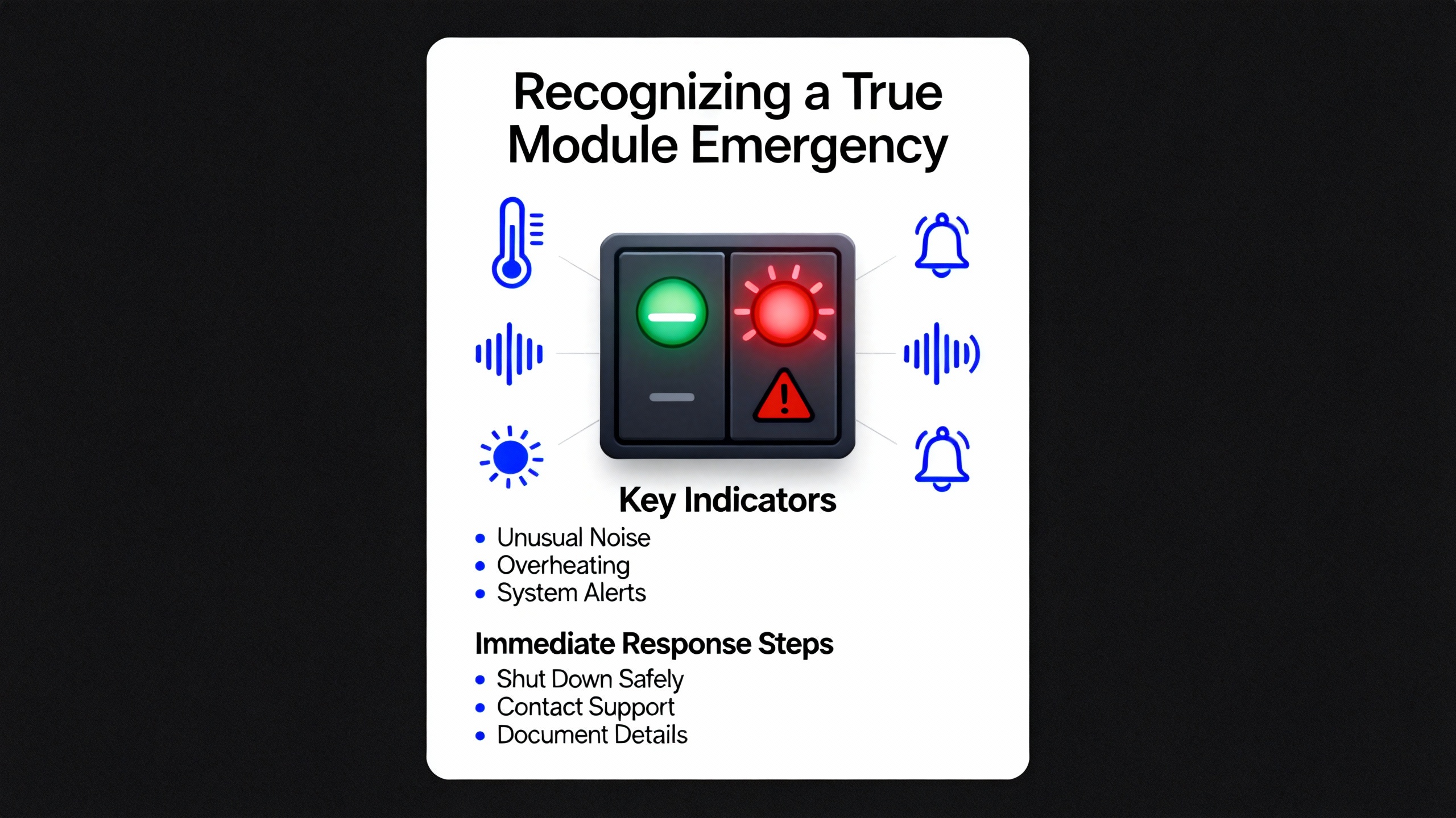
In every serious guide, troubleshooting starts with safety. The Digi-Key troubleshooting article, PLC training programs, and industrial safety standards all make the same point: a fast repair is never worth an injury.
Before opening a cabinet or touching a module, you should follow your plantŌĆÖs lockout/tagout procedures, isolate energy sources, and verify zero energy on the loads you will be near. Confirm emergency stops are effective and consider mechanical hazards as well as electrical ones. In high-inertia systems, stored energy in hydraulics, pneumatics, or rotating parts can cause serious injuries even after power is removed.
An emergency guide for refrigerator processing lines emphasizes ŌĆ£containmentŌĆØ as stage one. That means ensuring conveyors, robots, and valves are in fail-safe positions and verifying with operators that nothing can move unexpectedly while you are working. It also recommends designating a clear communicator to keep production, maintenance, and safety staff aligned. In practice, I have found that one calm person explaining what is happening and what will happen next reduces pressure on the technician in the panel and prevents well-meaning bystanders from making unauthorized changes.
Only when the system is stable and made safe should you move into diagnostic work inside the control cabinet.

Under pressure, there is a strong temptation to jump straight to swapping hardware. The more plants I have supported, the more I have seen that this is how you lose time and sometimes corrupt a perfectly good system. The fastest path out of an emergency usually begins with a structured triage.
Start with power and grounding. Multiple sources, including AutomationDirectŌĆÖs PLC handbook and AESŌĆÖs troubleshooting guidance, treat power quality as a primary suspect. Confirm with a meter that the PLC power supply is receiving the correct input voltage and delivering stable DC output. Inspect for blown fuses, loose terminals, and signs of overheating. If recurring faults disappear after a power supply swap or after stabilizing the incoming power, you may not need to touch any I/O or communication modules at all.
Next, walk the physical wiring. IndustrialAutomationCoŌĆÖs troubleshooting guide reminds technicians that loose or damaged connectors can mimic serious PLC failures. Tightening a terminal or replacing a damaged connector has saved more ŌĆ£deadŌĆØ PLCs than most people admit. Look for pulled wires, corrosion, signs of arcing, and any recent work that may have disturbed cables.
With basic power and wiring verified, move to software diagnostics. Modern tools such as Studio 5000, RSLogix, and other vendor environments expose real-time status of modules, fault histories, and sometimes even backplane diagnostics. Rockwell-focused troubleshooting articles recommend comparing the running program against your known-good backup. If the code has drifted or memory is corrupted, reloading a verified program may clear some issues without touching the hardware.
Environmental checks should not be skipped. Solution-focused maintenance articles recommend checking cabinet temperature, airflow, dust accumulation, and vibration. If you see warped plastic, discolored modules, or smell burnt material, treat that as evidence of stress on hardware and not just a nuisance alarm.
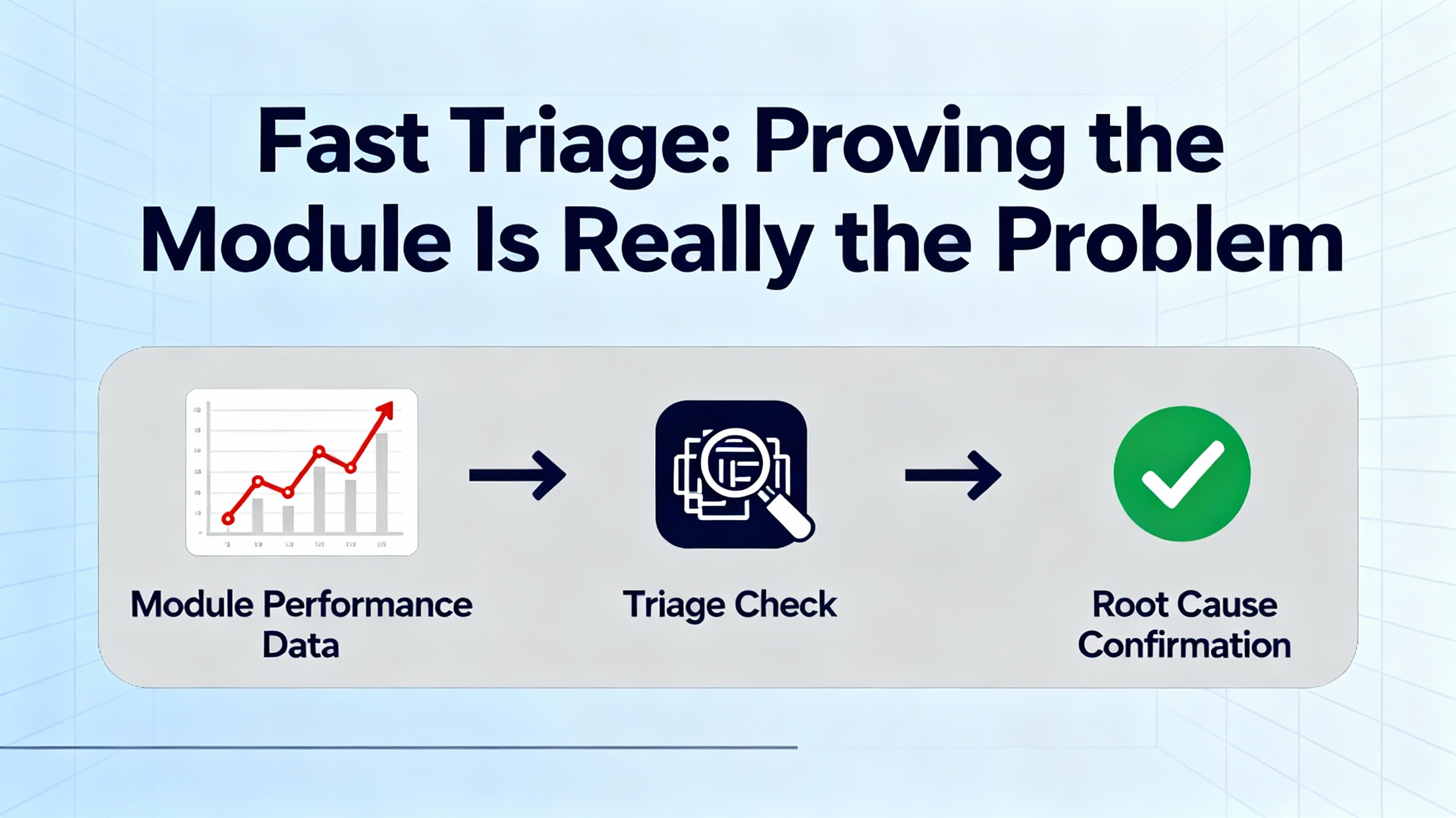
Only when power, wiring, configuration, and environment have been checked should you treat the module itself as suspect. At that point, the most decisive technique is the substitution method described in PLC communication and module failure guides: temporarily replace the suspected module with a known-good spare of the same type and configuration. If the fault follows the module, you have strong evidence that replacement is justified. If the fault remains, you are likely dealing with upstream or downstream issues rather than a bad card.
In an emergency, the default decision is usually to replace the module with a spare. Repair services such as those described by Global Electronic Services and AES often shine in post-event work, when you send failed modules out for cost-effective board-level repair rather than scrapping them.
Repair is attractive when the failure is minor, such as a blown fuse or a slightly damaged connector, or when the module is expensive, rare, or obsolete. However, these same sources point out that burned-out circuits, repeated faults after resets, and extensive physical damage typically justify full replacement, especially when production is stopped.
The choice is not purely technical; it also depends on the lifecycle strategy for your control system. Articles on maintaining custom PLC systems and on PLC maintenance best practices encourage plants to track obsolescence, plan migrations, and maintain a small but strategic inventory of critical spares. In that context, even moderately repairable modules may be replaced in an emergency, then evaluated for repair later, so that the spare stock remains healthy.
A practical way to think about the trade-off is summarized below.
| Option | Pros | Cons | Best use case |
|---|---|---|---|
| Immediate module replacement | Fastest path to restart, minimal diagnostics during the swap, strong proof of failure | Requires compatible spare, risk of configuration mismatch, may not address underlying root cause | Critical production stopped, compatible spare on hand, fault clearly follows the suspect module |
| Field-level repair only | No spare required, low component cost for minor issues | Slow, limited by in-house skills, risk of incomplete fix, may void certifications | Non-critical systems, minor visible damage, or as a temporary measure while planning full replacement |
| Third-party repair service | Professional diagnostics, board-level repair, sometimes warranty | Requires shipping time, not useful in the immediate emergency | Long-term cost control and extending life of obsolete or expensive modules |
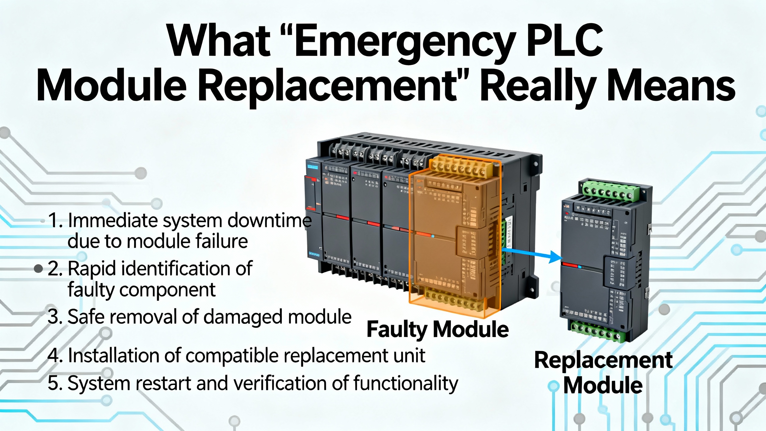
Once you are confident that a module needs to be replaced and you have a compatible spare, the real work begins. A good procedure balances speed with traceability and reversibility. What follows aligns with stepwise methods advocated by PLC troubleshooting guides, emergency recovery articles for refrigeration lines, and vendor recommendations, translated into the reality of a busy plant floor.
The first step is to capture the current state. Even in a crisis, take a minute to document what you are about to change. Photograph the rack and the suspect module from multiple angles, making sure you can see keying positions, terminal labels, and any DIP switches or address selectors. Note the moduleŌĆÖs catalog number, firmware revision if visible, and any unusual LED states. If your plant uses a computerized maintenance system or logbook, start a record now with timestamp, machine name, and observed symptoms.
Next, secure your backups and configuration. Maintenance best-practice articles emphasize the importance of having recent, verified backups of PLC programs and hardware configurations. If the controller is still reachable, connect with the appropriate software, upload the current project, and save it with a timestamped file name. For communication modules, make sure you export any configuration, such as IP addresses, protocol settings, or scan lists. For I/O modules in platforms where configuration is stored in the CPU, verify that the replacement module is the same model and revision, or be prepared to adjust the configuration according to the vendorŌĆÖs guidance.
With documentation and backups in place, shut down power to the affected rack or module unless your system explicitly supports hot-swapping and you are following vendor-approved procedures. Many field incidents and subtle backplane faults arise from ad hoc ŌĆ£liveŌĆØ replacements that were never validated by the manufacturer. When in doubt, plan for a controlled power-down, confirm with a meter that dangerous voltages are absent, and verify with operators that all motion is safely stopped.
During physical removal, handle the module as if you intend to repair it later, even if you suspect it is destroyed. Wear an anti-static wrist strap if available and attach it to a known ground. Carefully release the mechanical retainers, gently rock the module out of the backplane, and avoid bending or contaminating the edge connector. For removable terminal blocks, mark their orientation and position, and avoid tugging on wires. Field reports in emergency guides stress the value of labeled modules and terminal blocks; taking an extra moment now to confirm labeling prevents misplacement and cross-wiring when you are tired.
Install the replacement module by reversing these steps. Confirm that it has the correct keying, part number, and, where relevant, series or firmware range for your platform. Fully seat it into the backplane until latches or screws are secure. Reinstall terminal blocks or connectors, checking that each point returns to the correct position. Any lingering doubt about a connection should be resolved by comparing with your reference photos or the wiring diagram.
When you restore power, watch the rack and module status carefully. Articles on communication module troubleshooting recommend paying particular attention to the power and communication LEDs: a healthy communication module generally shows a stable power indicator and a blinking communication indicator when data flows. For I/O modules, verify that their status LEDs move through the expected sequence as the CPU resumes scanning.
The next stage is functional verification. Start with a dry check in programming software. Use real-time views of the input and output image tables to verify that the new module is being recognized correctly, shows healthy status, and is not triggering faults. For I/O, exercise each critical point in a controlled way, either through test switches, maintenance modes, or carefully coordinated manual commands. For communication modules, confirm that HMIs, SCADA systems, and peer PLCs can connect, exchange data, and operate normally.
Only after this controlled verification should you release the line to production, and even then, you should stay nearby for the first full cycle. A structured six-step troubleshooting process used in technical training emphasizes the importance of failure analysis and recording. Do not skip the final step of documenting what failed, how you diagnosed it, what you replaced, and any residual concerns. This record becomes invaluable the next time the line misbehaves or a different technician is tasked with explaining past events.
Communication module failures deserve special attention because they often present as ŌĆ£everything looks fine in the rack, but operators cannot control the machine.ŌĆØ A practical guide to communication module troubleshooting stresses that you should rule out configuration and network issues before condemning the hardware. That means verifying network settings, checking for address conflicts, confirming protocol and baud-rate alignment, and testing cables with network testers or meters.
When a communication module truly fails, the emergency replacement procedure adds a configuration layer. You must ensure that the new module carries the same logical identity as the old one, whether that is an IP address, a node number, or a slot-based configuration in the PLC program. If this mapping is wrong, you may restore basic connectivity while silently breaking data exchanges or safety interlocks. After replacement, use both diagnostics and functional tests to prove that critical alarms, commands, and interlocks still reach their destinations.
CPU module failures are rarer but more disruptive. A detailed troubleshooting flowchart from a supply house recommends exhausting power, memory, program integrity, I/O, field devices, communication links, and environmental checks before declaring a CPU bad. When everything else checks out and the CPU continues to fault or refuses to run a known-good program, replacement is the remaining option. In an emergency, this is only safe if you have a verified backup of the application, clear documentation of hardware revisions, and, ideally, vendor or specialist support on standby. RockwellŌĆÖs TechConnect and similar vendor support programs exist precisely for these high-stakes scenarios and can significantly shorten downtime when complex interactions or corrupted memory structures are involved.
The best emergency replacement is the one you never have to perform. Across sources that focus on PLC maintenance and reliability, a few practices repeatedly emerge as the difference between constant firefighting and controlled, predictable operation.
First, disciplined backups are non-negotiable. Rockwell-focused troubleshooting guides recommend backing up programs at least quarterly and after any significant change. Tools such as Rockwell AssetCentre can automate plant-wide backups. Other maintenance articles stress that backups should be stored securely, version-controlled, and periodically tested by performing restore simulations. Without working backups, a failed CPU or corrupted memory can turn a short outage into a prolonged reconstruction project.
Second, environmental and power quality control dramatically reduce hardware stress. Allied Reliability and Solution Controls highlight dust, heat, and moisture as quiet killers of PLC hardware. Keeping cabinets clean, maintaining adequate ventilation, staying within manufacturer temperature limits, and using surge protection, voltage regulation, and proper grounding all extend module life and make emergency failures less frequent.
Third, scheduled health checks catch problems early. Hale EngineeringŌĆÖs maintenance recommendations for Allen-Bradley systems, for example, suggest firmware and software reviews, diagnostics and network checks, and environmental inspections on a regular cadence, with more thorough professional health checks yearly. Checking batteries proactively, inspecting I/O modules for corrosion or looseness, trending scan times and memory usage, and reviewing network error counters all help you schedule interventions during planned downtime rather than on a frantic phone call.
Fourth, trained people and clear documentation matter as much as the hardware. Maintenance-focused integrators and training programs emphasize that technicians who understand both the control structure and the physical process make better decisions under pressure. Good tag naming, up-to-date drawings, and machine-specific troubleshooting guides reduce guesswork. Logs that capture symptoms, actions, and root causes turn one painful incident into learning for the whole team.
Finally, safety and cybersecurity should be integrated into maintenance. Standards such as NFPA 79 for electrical safety of machinery, IEC 61131-3 for programming structure, and ISA/IEC 62443 for industrial cybersecurity provide frameworks to keep PLC systems reliable and safe. Cybersecurity-focused maintenance, including controlled access, change management, and secure firmware updates, prevents configuration tampering that could masquerade as hardware failure.
Use a combination of status LEDs, software diagnostics, and meter readings. If an input LED on the module never turns on but you can measure the correct signal at the terminal, suspect the module. If the LED changes but the corresponding bit in the program does not, suspect configuration. If neither changes and you measure no signal, the sensor or wiring is more likely at fault. For outputs, if the program bit is on, the module LED is on, but the field device does nothing and there is no voltage at the terminals, suspect the module; if there is voltage at the terminals but the device is silent, suspect the device or its power source.
Only if your specific hardware platform and vendor documentation explicitly support hot-swapping for that module type, and only under a documented procedure. Many industrial articles describe module replacement with the system powered down to avoid backplane damage and unintended motion. In an emergency, the safest default is to plan for a controlled shutdown, unless a qualified engineer and the manufacturer both confirm that live replacement is supported and acceptable for your risk profile.
This is where backup discipline pays off. If you have a verified backup, connect to the new CPU with the appropriate programming software, confirm firmware compatibility, and download the master program. If no backup exists, do not attempt to ŌĆ£rebuildŌĆØ the program from memory under production pressure. Keep the system in a safe state, involve engineering leadership and, if needed, vendor or integrator support. In many cases, the safest approach is to keep the line down and reconstruct the control logic carefully rather than improvising a partial program that could introduce safety or quality risks.
At the end of the day, emergency PLC module replacement is not about clever tricks; it is about methodical, practiced habits executed under pressure. Stabilize the process, prove the fault, replace the right module the right way, and then change your maintenance and backup practices so that the next time something fails, it feels less like a crisis and more like a well-rehearsed drill.


Copyright Notice © 2026 mooreautomated.com All rights reserved,Moore Automated is not an authorized distributor or representative of the manufacturers featured on this website. Brand names and trademarks featured are the property of their respective owners.


Leave Your Comment