


MP 3009X
Get A Quote
When a Bosch Rexroth servo drive throws an encoder error, production does not usually explode in a dramatic way. What actually happens is more frustrating: a packaging axis hunts around its target, a CNC table drifts out of tolerance, a labeling wheel stops with no obvious reason, and the HMI just flashes an encoder fault. As an onŌĆæsite automation engineer, these are the calls that usually come in just before a big order has to ship.
This guide walks through how to understand, diagnose, and prevent encoderŌĆærelated faults on Bosch Rexroth servo drives using principles that apply across modern servo platforms. It blends field practice with recommendations echoed by respected sources such as BIN95, Delta Automation, UpFix, Global Electronic Services, and Mitchell Electronics. The goal is simple: get the line running safely, without guessing, and keep it running longer.
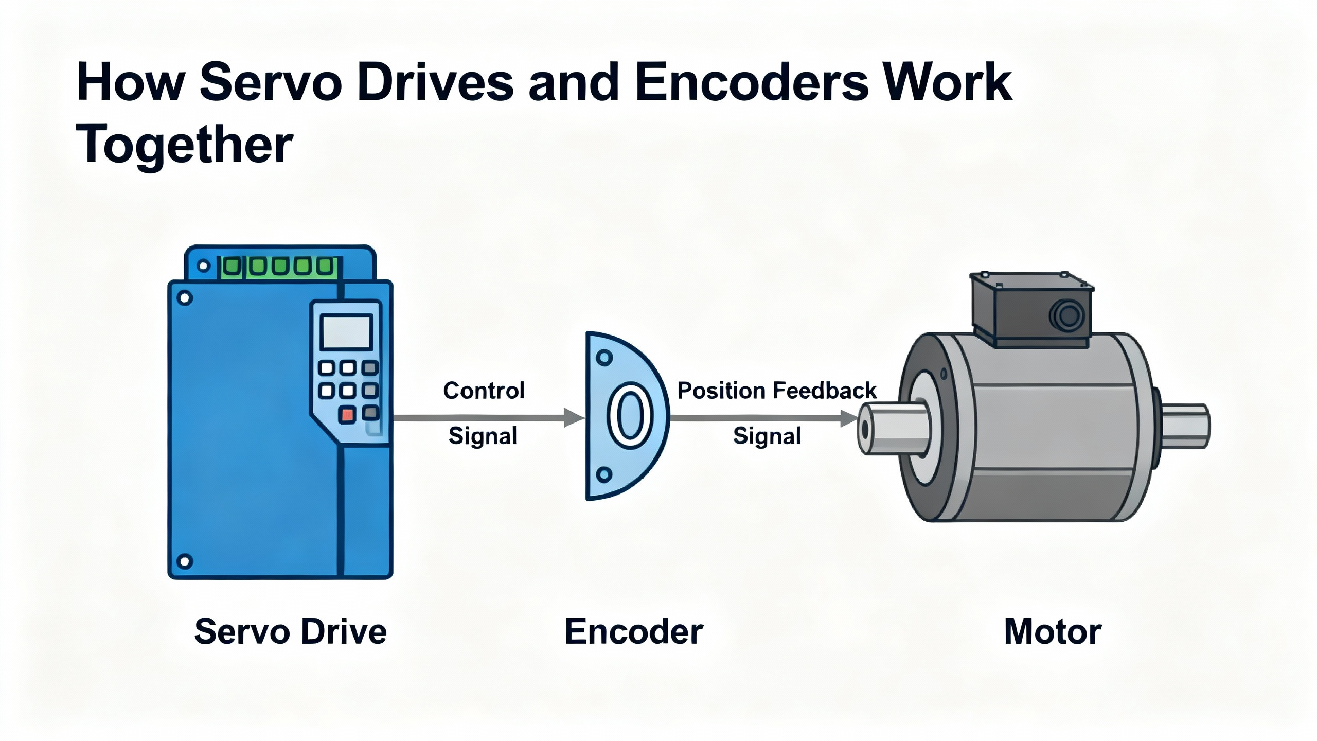
Servo drives, whether from Bosch Rexroth or any other major manufacturer, are power electronics that take lowŌĆælevel command signals and turn them into controlled torque, speed, and position at the motor. BIN95 describes the drive as the device that manages power delivery while watching feedback from encoders or resolvers to close the loop.
In a typical servo axis you will find a few core elements working together. The controller, often your PLC or motion CPU, generates the position or speed commands. The servo drive regulates power so the motor follows those commands. The servo motor converts that electrical power into mechanical motion. The encoder or resolver reports the actual position and speed back to the drive so it can continuously correct any error. Notes from UpFix and THM Huade both emphasize that this feedback device is absolutely critical for precision and for safety.
Encoders themselves come in several flavors. Incremental encoders output pulse trains, frequently in quadrature A and B channels with an optional Z index pulse per revolution. Absolute encoders report a unique positional value for each shaft position so the drive knows position immediately at powerŌĆæup. Optical encoders use a light source and code disk; magnetic designs use magnetic fields and HallŌĆæeffect sensors, as described by ACS Industrial and Global Electronic Services. Each technology has different strengths with regard to contamination, noise susceptibility, and cost.
Regardless of type, the servo drive expects encoder signals that are clean, consistent, and synchronized with the commanded motion. When those expectations are not met, the drive raises an encoder or feedback error and, if properly configured, shuts down motion to avoid a runaway event.
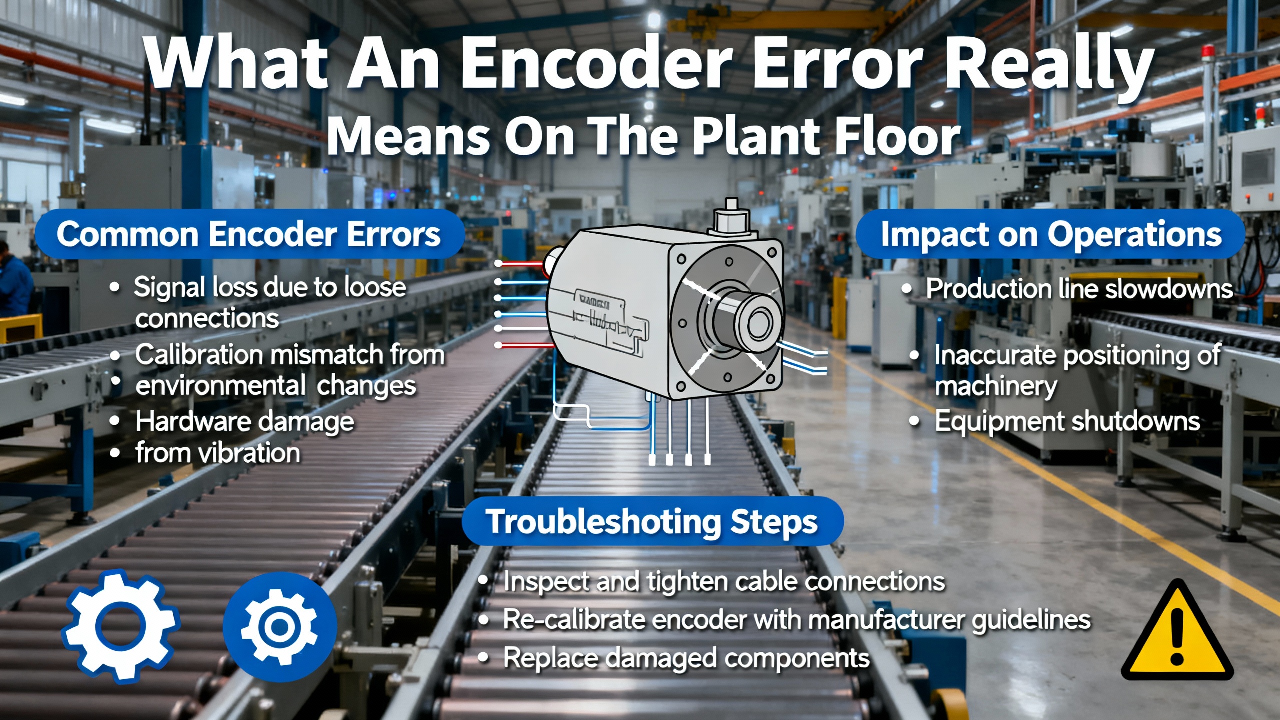
On the floor, encoder problems rarely announce themselves with a single neat alarm. Delta Automation and Global Electronic Services both note that encoder issues often present as progressive symptoms before there is a hard fault.
You may see unpredictable or jerky motor movement even while the position command looks clean. Position may slowly drift away from programmed coordinates, with growing error over time. The drive or CNC will start logging servo alarms or following errors that clear temporarily after a reset but keep coming back. In the worst case, the drive reports an encoder error and refuses to enable, or you experience a ŌĆ£runawayŌĆØ event where the axis tries to move uncontrollably because feedback disappears, which UpFix flags as a classic lossŌĆæofŌĆæfeedback condition.
From the driveŌĆÖs point of view, an encoder error generally means one of a few things. The encoder signals are missing entirely. The signals are present but electrically out of tolerance, noisy, or distorted. The relationship between channels is wrong, such as incorrect phasing between A and B. The reported movement does not match what the drive believes it commanded, often because of misconfiguration or a mechanical problem. When that happens, the drive faults to protect the machine and the operators.
Multiple independent sources point to the same families of root causes when dealing with encoder errors on servo drives. Understanding these groups helps you troubleshoot quickly and avoid chasing ghosts.
Electrical and cabling problems are often at the top of the list. ACS Industrial, Mitchell Electronics, and Haas CNC service material consistently highlight loose or damaged encoder cables, bent pins, corroded contacts, and poor shielding or grounding. Long runs next to highŌĆæcurrent motor or VFD cables inject electrical noise into encoder lines, which shows up as erratic counts or spurious faults. Incorrect supply voltage to the encoder, whether too high, too low, or unstable, also leads to missing or distorted signals, as Manufacturing Tomorrow emphasizes.
Mechanical issues are another major category. Global Electronic Services points out that even a small shift in encoder mounting or bearing wear can distort alignment enough to create significant position errors. Misaligned couplings, loose set screws, damaged shafts, or worn motor bearings change the relationship between the motorŌĆÖs actual position and what the encoder thinks it is. In some cases the encoder shaft itself becomes rough to rotate, which GES flags as a sign of bearing failure inside the encoder.
Environmental contamination tends to creep up over time. ACS Industrial notes that optical encoders are vulnerable to dust or oil on the disk, causing missing pulses or complete loss of rotation feedback. Moisture ingress through cable glands or damaged seals leads to sporadic failures that are difficult to reproduce. Overheating from hot motor exhaust air or poor cabinet cooling can eventually cause total encoder failure. KEB America also stresses that contamination by coolant, oil, and dirt is a key driver of servo motor and feedback device failures.
Configuration and control issues form the last major group. Industrial Automation Co. and the Yaskawa troubleshooting guide summarized by MRO Electric both stress that drives are sensitive to incorrect parameters, including encoder type, resolution, steps per revolution, and scaling to mechanical travel. Haas documentation shows how encoder counts must match the ball screw pitch per revolution; when these numbers do not line up, you will see position errors and faults even with perfectly healthy hardware. Firmware mismatches and unrecorded parameter changes also cause intermittent and ŌĆ£weirdŌĆØ encoder error behavior.
The same few symptoms tend to recur across Bosch Rexroth and other servo platforms. The following table summarizes how they often map to deeper causes, based on patterns described by Delta Automation, Global Electronic Services, Manufacturing Tomorrow, and others.
| Visible symptom on the line | Likely problem category | Typical first checks on site |
|---|---|---|
| Jerky motion, hunting, or vibration | Noisy or intermittent encoder signals; misalignment | Inspect encoder and motor mounts, check cable strain relief and shielding |
| Repeated encoder or following error alarms | Loose or damaged encoder cabling; contamination | Reseat connectors, inspect pins, look for oil or dust at encoder housing |
| Axis drifts or loses position over several moves | Bearing wear or small mounting shifts; mis-scaling | Check mechanical integrity, verify encoder resolution and scaling settings |
| Drive will not enable due to encoder fault | No encoder power; cable failure; dead encoder | Confirm supply voltage, check cable continuity, try known-good encoder |
| Occasional runaway or violent jump on enable | Loss of feedback; encoder misalignment or mismatch | Cut power, verify feedback wiring, alignment, and commutation parameters |
This table is not a replacement for the Bosch Rexroth documentation, but it lines up closely with what repair centers and field technicians see in practice.
Unstructured encoder troubleshooting quickly turns into trial and error, which Mitchell Electronics warns against. A disciplined flow saves time and prevents new faults. The sequence below is the same pattern I follow on site for Bosch Rexroth and other drives, adapted from best practices published by BIN95, Industrial Automation Co., UpFix, and encoder specialists.
Servo drives and motors retain energy even when the main disconnect is off. BIN95 and XŌĆæTEAM both stress electrical and mechanical safety before any encoder work. Shut down the machine using proper lockout and tagout, and verify that all relevant sources are deŌĆæenergized. Allow the DC bus capacitors in the drive to discharge fully; on older cabinets I assume they are still charged until I have waited the manufacturerŌĆÖs recommended time and confirmed with a meter where appropriate.
Secure or mechanically block any axes that could move under gravity or spring force. Do not rely solely on the brake, especially since KEB reminds us that servo brakes are primarily holding devices, not dynamic stopping systems. If you will handle encoder electronics or open a drive, use ESD protection and insulated tools. Only when the system is electrically safe and mechanically stable is it time to begin diagnosis.
Modern servo drives maintain rich fault histories. BIN95, Industrial Automation Co., Delta Automation, and YaskawaŌĆÖs DriveWizard documentation all highlight the value of reviewing fault logs rather than simply clearing them. On a Bosch Rexroth drive, start at the HMI or drive display and capture the exact encoder or feedback error code, any subcodes, and the time stamps or counters if available.
Then, in the Rexroth manual, look up the faultŌĆÖs formal description and recommended checks. Even if the manual language is generic, it usually tells you whether the drive is complaining about loss of feedback, signal quality, configuration mismatch, or internal hardware. Take a minute to note what the axis was doing at the time of fault: accelerating, holding position, creeping slowly, or standing idle. Those context clues will matter later, especially if the fault only appears at certain speeds or duty cycles.
Almost every reputable source, from UpFix to Global Electronic Services, puts visual inspection at the top of the troubleshooting list, and for good reason. On a Bosch Rexroth axis, remove guards as safely allowed and get eyes and hands on the motor, encoder, cabling, and surrounding mechanics.
Look for broken or crushed encoder cables, compromised insulation, or sections that have been rubbing across sharp edges. Check for oil or coolant wicking into the encoder housing or cable glands. Confirm that connectors are fully seated, locking mechanisms are engaged, and strain reliefs are properly clamped. ACS Industrial notes that many encoders that appear electrically ŌĆ£deadŌĆØ turn out to have simple connection issues.
Next, gently check the mechanical side. Rotate the axis by hand where safe and possible, or decouple the motor from the load. Feel for roughness or tight spots that might indicate bearing wear in the motor or the encoder. Press on couplings and mounts to detect looseness. Global Electronic Services stresses that even a slight movement at the encoder mount can accumulate into large positioning errors.
If you find obvious physical damage, contamination inside an optical encoder, or a mount that has clearly slipped, document everything with photos and correct those issues before diving into deeper electrical tests.
Once physical inspection is complete, the next logical question is whether the encoder is receiving clean power and has a continuous signal path back to the Bosch Rexroth drive.
Manufacturing Tomorrow recommends checking for correct supply voltage whenever there is no encoder output. With the system made safe and the relevant circuits reŌĆæenergized only as needed for measurement, confirm that the encoder supply at the drive end matches what the encoder requires according to its nameplate and data sheet. Do not assume; verify both voltage magnitude and polarity.
Haas service procedures advise checking encoder cable resistance leg to leg and leg to ground, expecting open circuits where shorts are not allowed. While specific values depend on the cable design, you are essentially looking for signs of crushed sections or moisture ingress that created leakage paths. If your continuity tests are inconsistent as you flex the cable, suspect internal conductor breaks.
Reseat the cable at both drive and encoder ends, making sure each plug is in the correct receptacle. More than once, I have found swapped feedback and I/O connectors after a rushed motor change, which guarantees encoder errors on powerŌĆæup.
When power and continuity look good but the Bosch Rexroth drive still reports encoder problems, the next layer is signal integrity. Global Electronic Services and Dynapar both stress the value of examining encoder waveforms directly. If you have access to an oscilloscope and the necessary isolation, observe the encoder outputs at the drive terminals while jogging the axis slowly.
Incremental encoders should produce clean, regular square waves on the A and B channels, ninety electrical degrees out of phase, with consistent amplitude. Absolute encoders using serial interfaces should show stable, repeatable signal patterns without excessive jitter or noise. Any irregular, missing, or noisy pulses suggest electrical interference, contamination on an optical disk, misalignment, or internal encoder damage.
If you do not have a scope, many modern drives, including those from Yaskawa as described in the MRO Electric summary, provide internal diagnostics that display raw encoder counts or feedback status. Bosch Rexroth platforms usually offer similar views. Use these diagnostics to confirm that counts increment smoothly and repeatably when you move exactly one mechanical pitch or revolution, similar to the method Haas describes for verifying steps per revolution against ball screw pitch. If counts jump, stall, or vary from move to move, the encoder or its configuration is suspect.
If hardware looks solid and signals are at least present, configuration often becomes the culprit. Industrial Automation Co., MRO ElectricŌĆÖs Yaskawa guide, Manufacturing Tomorrow, and Haas all highlight the importance of matching drive parameters to the actual encoder and mechanics.
On a Bosch Rexroth drive, confirm that the configured encoder type matches the installed device: incremental versus absolute, optical versus magnetic if relevant, and any protocol or interface mode. Check that resolution values, such as counts or cycles per revolution, agree with the encoder specifications. Then verify scaling from encoder counts to mechanical travel, using methods comparable to jogging exactly one ball screw pitch and comparing counts.
Review control loop parameters as well. Badly tuned gains may masquerade as encoder issues, especially when they cause oscillation or overshoot, which MRO Electric and UpFix both flag as common symptoms. Restore knownŌĆægood parameter sets from backups where possible, a practice THM Huade and UpFix strongly recommend before making changes, and compare firmware versions with Bosch Rexroth guidance if the drive has been recently updated or replaced.
If you discover that parameters were changed without documentation, treat this as a configuration drift problem. Document the asŌĆæfound values, align them with Rexroth recommendations and mechanical realities, and retest.
BIN95 and ACS Industrial both note that swapping suspected parts with knownŌĆægood ones is often faster and more reliable than guessing. Once you have exhausted noninvasive checks, you can use controlled swaps to isolate whether the encoder, motor, cable, or drive electronics are at fault.
If another identical axis exists on the same machine, temporarily swapping encoder cables at the drive side can show whether faults follow the cable or stay with the drive. Swapping only the encoder, while keeping the same motor and cable, reveals whether the encoder unit itself is defective. In all cases, label everything clearly, change one variable at a time, and follow Bosch Rexroth and plant safety rules.
Mitchell Electronics cautions that without proper alignment tools, reattaching an encoder to a servo motor can introduce misalignment that causes new problems or masks the original fault. If you do not have the fixtures and training to perform encoder alignment, seriously consider sending the motor and encoder assembly to an experienced repair center.
Several sources, including UpFix, Global Electronic Services, and Mitchell Electronics, emphasize that servo and encoder repair is specialized work. Deep issues such as internal encoder electronics failure, complex commutation alignment problems, or intermittent faults that only appear at high speed often require labŌĆægrade diagnostic gear and fixtures.
Signs that it is time to escalate include encoder errors that persist after you have verified power, cabling, mechanical mounting, and configuration; runaway or severe instability that cannot be safely replicated for testing; and drives that show mixed or cryptic fault codes even after firmware and parameter checks. At that point, Bosch Rexroth technical support or a certified repair house with servo test benches is the better option than continued onŌĆæsite trial and error.
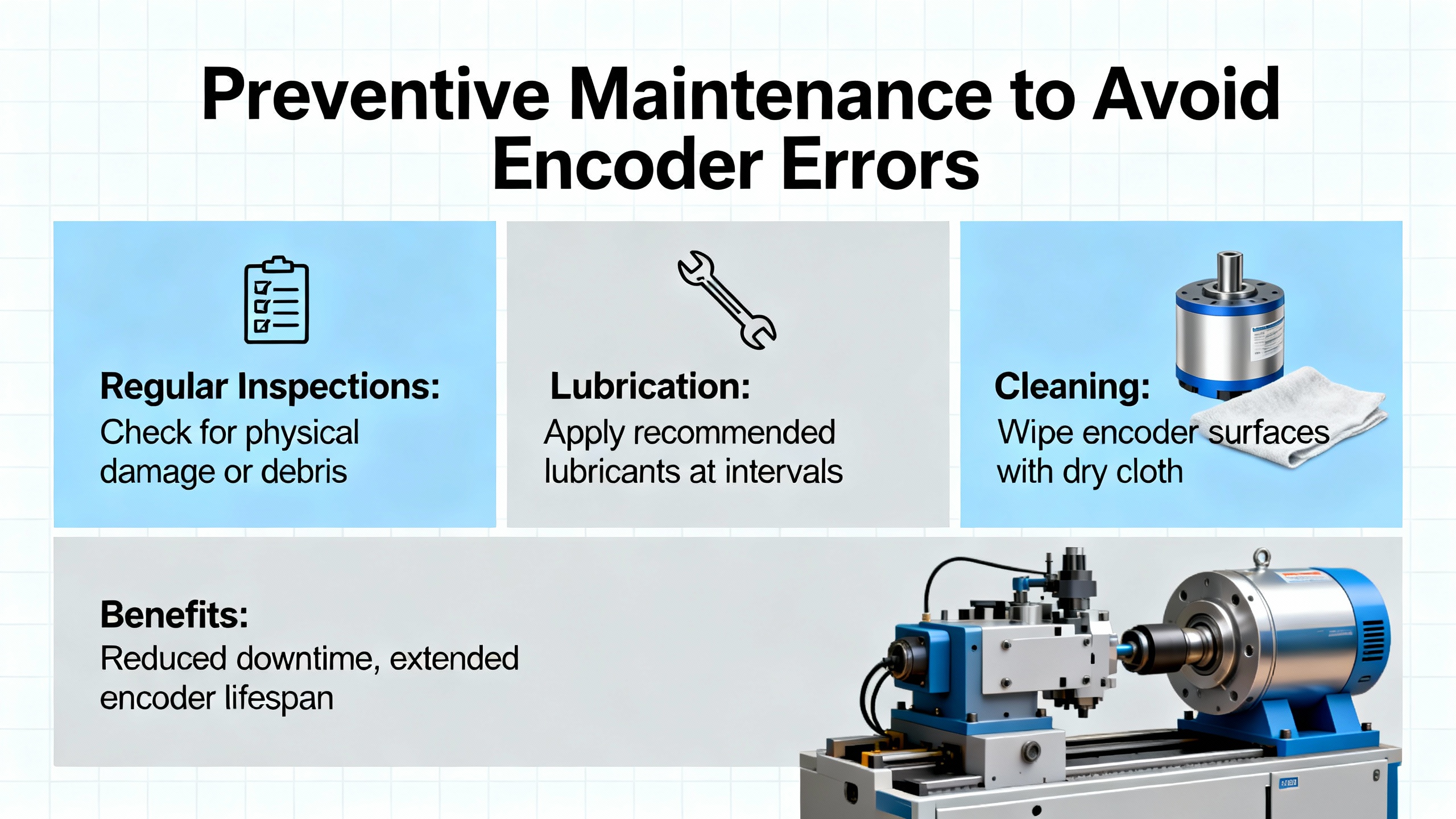
Almost every article in the research set converges on the same conclusion: most servo and encoder failures start as small, preventable problems. BIN95, UpFix, THM Huade, Delta Automation, KEB, and others all promote structured maintenance rather than waiting for faults.
For Bosch Rexroth systems, that maintenance should cover both the drive environment and the encoder hardware. Keep drive cabinets clean, dry, and well ventilated. BIN95 suggests service intervals of roughly a year for light duty and as short as three to six months for harsh, continuous operation; UpFix recommends routine checks every three to six months and even monthly in demanding environments. Cleaning fan inlets, filters, and heat sinks reduces overheating that can damage encoders mounted on hot motors.
Inspect wiring and connectors regularly. THM Huade and UpFix stress tightening terminals, replacing damaged cables, and checking grounding. For encoder cables, pay special attention to bend radius, strain relief, and routing away from noisy power cables. Global Electronic Services notes that proper shielding and physical separation of feedback lines from highŌĆæpower conductors dramatically reduces electrical interference.
On the mechanical side, follow KEB and UpFix guidance by monitoring for unusual noises and vibration, which often signal bearing wear or misalignment. Check motor mounts, couplings, and encoder brackets for looseness or fatigue. Addressing those small issues early prevents the microŌĆæshifts and misalignment that eventually trigger encoder errors.
Environmental control matters as well. ACS Industrial and KEB warn that oil, coolant, and metal dust are enemies of encoders. Use covers, better sealing, and proper cable glands to keep contaminants out. Where washdown or moisture is unavoidable, consider more robust feedback devices with improved sealing, as Global Electronic Services suggests.
Finally, make parameter and firmware management part of your maintenance discipline. THM Huade and UpFix both recommend backing up drive parameters before changes and maintaining clear records. When you upgrade firmware on a Bosch Rexroth drive, verify encoderŌĆærelated settings afterward and retest axes under controlled conditions to catch any incompatibilities before they hit production.
When a Bosch Rexroth servo drive shows encoder errors, you face a decision about how far to go inŌĆæhouse. The research notes highlight three basic paths, each with pros and cons.
Repairing the existing encoder or motor assembly through a qualified repair center is often costŌĆæeffective. ACS Industrial and Global Electronic Services both argue that many encoders and servo motors that appear to be dead can actually be repaired economically, with multiŌĆæyear warranties and quick turnaround times. UpFix cites substantial customer savings when repair is chosen over full replacement, along with improvements in reliability after proper refurbishment.
Replacing the encoder with a new unit is the straightforward option when there is obvious physical damage, severe contamination, or when the encoder model is relatively inexpensive. Manufacturing Tomorrow recommends replacing encoders that are visibly or functionally damaged after you have verified correct installation and cabling. When you do this on a Bosch Rexroth system, ensure the replacementŌĆÖs electrical characteristics and resolution match what the drive expects, and follow the installation and alignment instructions closely.
Sending the motor and encoder assembly, or even the drive, to a specialist or to Bosch Rexroth service is the safest route when you lack the tools or experience for proper diagnosis and alignment. Mitchell Electronics explains how attempting servo repairs without purposeŌĆæbuilt tools leads to misdiagnosis, repeat failures, and higher longŌĆæterm costs. Complex encoder alignment, in particular, is not something to tackle with generic tools and a guess.
In practice, I usually handle basic checks, cabling, cleanliness, and obvious mounting issues on site. When I encounter persistent encoder faults after those steps, or when alignment is required, I document everything, pull full parameter backups, and then either arrange for OEM support or ship the affected components to a trusted repair partner.
Running with known encoder issues is a risky bet. The research from Delta Automation, Global Electronic Services, and KEB shows that early warning signs usually precede more serious failures. Intermittent encoder faults can escalate into sudden runaways, uncontrolled motion, or repeated emergency stops that are harder on mechanics than a controlled shutdown. In a safetyŌĆæcritical environment, it is far better to schedule a short, planned downtime to address encoder problems than to wait for an uncontrolled stop that may damage tooling or injure personnel.
You can get a long way without a scope by following the structured checks advocated by BIN95, UpFix, and Manufacturing Tomorrow: visual inspection, cable continuity, power verification, and parameter review. Many Bosch Rexroth drives provide internal diagnostics that show raw encoder counts and error status, similar to capabilities described in Yaskawa and Haas documentation. However, when you suspect electrical noise or marginal signal quality, a scope or a dedicated encoder test tool gives you insight that basic meters cannot. Mitchell Electronics highlights that specialized tools dramatically reduce misdiagnosis, so for plants with frequent servo work, the investment is justified.
Global Electronic Services and ACS Industrial both recommend upgrading to encoders with better sealing and noise immunity when operating in environments with metal dust, oil mist, or strong electromagnetic interference. Optical encoders offer high resolution but dislike contamination; magnetic encoders better tolerate dirt and moisture but can be affected by strong magnetic fields and may have different noise behaviors. Work with Bosch Rexroth or a qualified encoder vendor to select a device whose environmental ratings and output format match your driveŌĆÖs capabilities, then ensure that cabling, grounding, and routing are upgraded at the same time. Installing a tougher encoder without cleaning up electrical and mechanical conditions rarely solves the root problem.
Closing this out as a field engineer, encoder errors on Bosch Rexroth servo drives are less about mysterious electronics and more about disciplined basics: safe lockout, careful inspection, clean power and cabling, verified configuration, and knowing when to hand the problem to specialists. If you treat each encoder fault as an opportunity to tighten up both maintenance and documentation, you will see fewer surprises, shorter stoppages, and a servo system that earns its place in your automation toolbox.


Copyright Notice © 2026 mooreautomated.com All rights reserved,Moore Automated is not an authorized distributor or representative of the manufacturers featured on this website. Brand names and trademarks featured are the property of their respective owners.


Leave Your Comment