


MP 3009X
Get A Quote
When a B&R slice dies at 2:00 AM and the line is bleeding money, the last thing you want is guesswork. Replacing B&R PLC modules is usually straightforward, but there are enough quirks around firmware handling, hardware visibility in Automation Studio, and legacy platforms that a sloppy swap can turn a quick repair into an extended outage.
This guide is written from the perspective of a field engineer who has had to nurse B&R systems back to life on live production floors. It draws on practical experience and on vendor and community knowledge from sources such as the B&R Community forum, technical notes summarized by ABB and RGB Elektronika, and migration advice from practitioners on MrPLC and Corso Systems. The focus is simple: help you replace B&R modules confidently, without breaking a working project.
PLCs are tough, but they are not immortal. Corso Systems highlights that controllers can fail due to physical damage, electrical events, or something as mundane as a dead backup battery combined with repeated power cycling. In many plants, the PLC outlives almost everything else, which means the system around it gets modernized while the controller hardware and protocols age in place. When a module finally fails, you may be dealing with a mix of legacy hardware, modern SCADA, and patched wiring that does not always match the drawings.
The CPU module itself is the brain of the system. RGB Elektronika describes how it runs the user program, manages inputs and outputs, handles diagnostics, and often takes care of tasks like error logging and firmware updates. If a CPU is sick, the whole machine is at risk. I/O slices, power supplies, drives, and backplanes may seem less critical, but a misconfigured or mismatched replacement can still pull a controller into service mode, trigger firmware conflicts, or quietly change behavior.
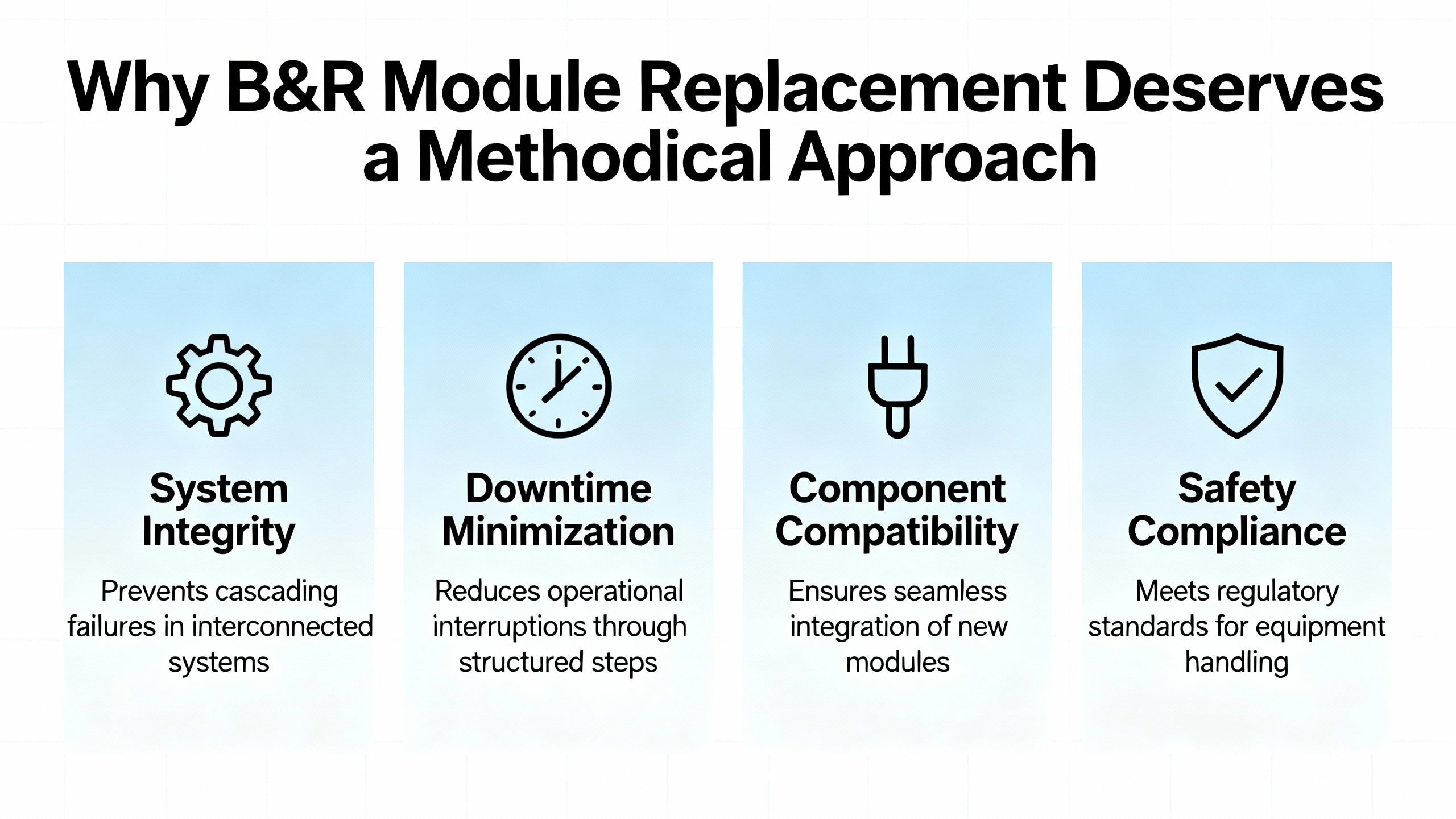
From a purely technical standpoint, B&RŌĆÖs ecosystem is helpful here. Modern systems manage firmware centrally, and B&R controllers tend to be forgiving when you swap a module for an identical part. At the same time, community threads show that simple visibility settings in Automation Studio can hide the modules you need to configure, and that diving into a legacy B&R 2005 project without the right tools and upgrade path can be hazardous. A methodical approach is how you keep a quick mechanical swap from turning into a software archaeology project.
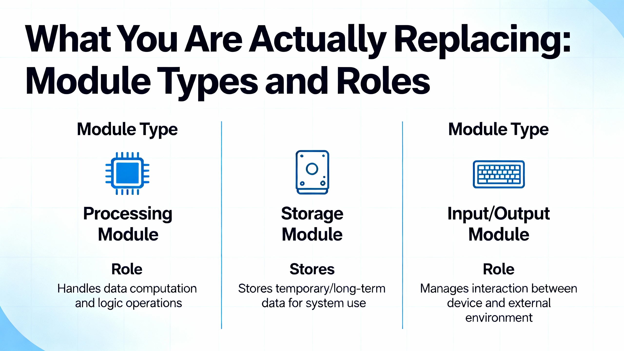
Every replacement job starts with being clear on what the module does and how the system sees it. The table below summarizes the main types of modules you will encounter in B&R systems and how sensitive they are to replacement decisions, based on the published descriptions of CPU behavior, I/O roles, and B&R migration experiences.
| Module type | Typical role | Replacement sensitivity |
|---|---|---|
| CPU controller | Executes user program, manages scan cycle, diagnostics, error logging, time | Very high; missteps can erase programs or lock system in error modes |
| I/O slices (X20 etc.) | Interface to field sensors and actuators | Medium; generally tolerant to identical like-for-like swaps |
| Power supply modules | Provide logic power and often output power to racks | High; wrong sizing or wiring can damage multiple modules |
| Backplanes/base units | Mechanical and electrical carriers (X20BM, BM11/BM01 etc.) | Medium; must match configuration and ensure correct addressing |
| Servo drives | Motion control, often managed via fieldbus and PLC firmware | High; firmware and parameter alignment are critical for safe motion |
The CPU carries the most risk. RGB Elektronika points out that persistent STOP or ERROR states, unresponsive communication ports, or repeated memory faults after verifying power and I/O often indicate the CPU itself is at fault and should be replaced or reconditioned. I/O slices, by contrast, are closer to consumables, provided the replacement matches exactly and the configuration still points to the same type.
B&R 2005 and X20 platforms also use base modules and power-supply modules to create isolated power groups, as practitioners outlined on MrPLC. Those base modules determine how nodes are addressed and how you can cut power to certain groups. If you replace them, you are touching the backbone for several slices, not just a single channel, so the risk is broader even if the swap looks mechanically simple.
The fastest way to waste a shutdown is to assume the faulty part is obvious. Before you pull a module, make sure you have enough evidence that it is the real culprit.
RGB Elektronika emphasizes that many symptoms that look like a bad CPU or module are actually caused by issues elsewhere. A PLC stuck in STOP, blinking error LEDs, random stops, unstable outputs, or communication failures can be traced to power supply problems, I/O faults, or firmware issues. Replacing the CPU or an expensive slice without checking those fundamentals can leave you with the same fault and a higher parts bill.
B&RŌĆÖs own ecosystem encourages a diagnostic-first approach. In a B&R Community thread about a CP340 controller stuck in service mode, experts insisted on pulling the controllerŌĆÖs error logbook before touching the project. They recommended connecting via the B&R Service Utility over a serial null-modem cable, selecting the correct COM port in Windows, and using the ŌĆ£Save Error LogbookŌĆØ function instead of immediately transferring a project that might not match the installed machine. The caution was clear: pushing an OEM project that is not an exact match may fail to fix the problem and can introduce new issues.
This mindset translates directly to module replacement. Before you declare a module dead, confirm that input power levels are correct, field wiring looks sane, and the controllerŌĆÖs logs do not point to a broader firmware or configuration issue. When in doubt, pull error logs or consult B&R support rather than guessing from LED patterns alone.
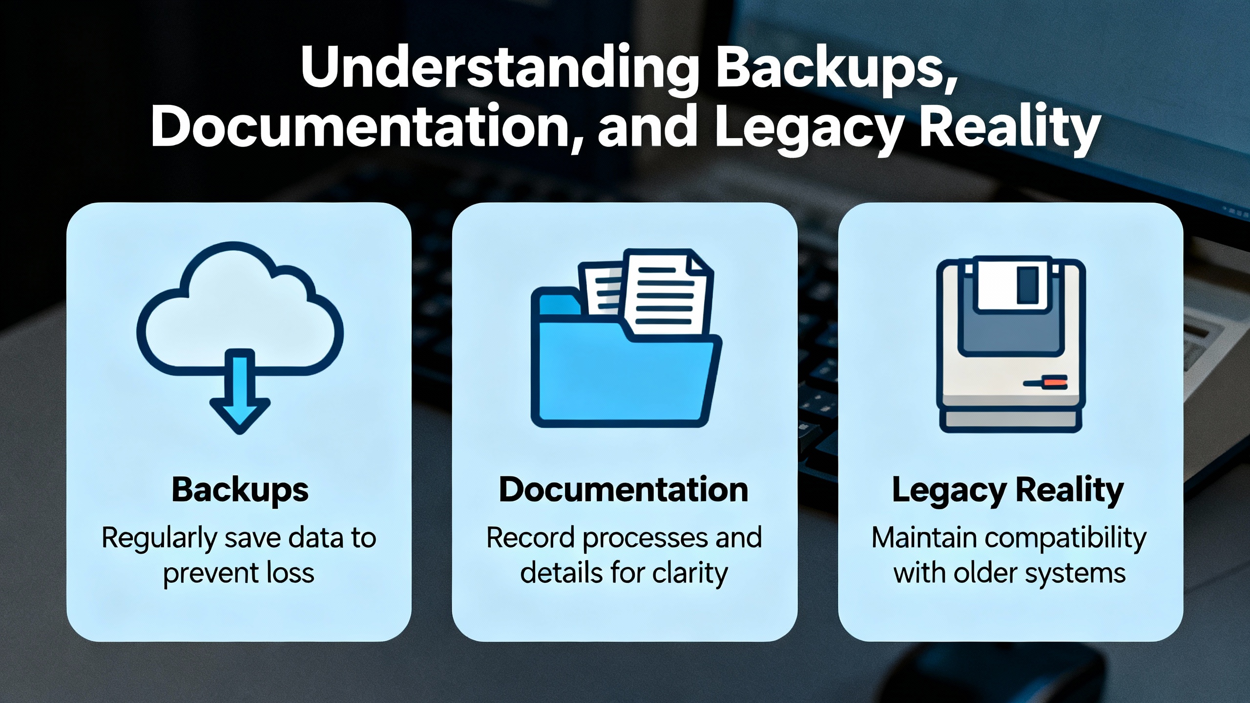
There is a recurring theme in the literature and in real plants: the documentation is often older than some of the technicians. Corso Systems notes that original panel drawings from 10 to 30 years ago rarely match the system after retrofits and field modifications. Legacy B&R 2005 projects may have been created with early Automation Studio versions, or even other B&R tools, and might exist only on a compact flash card or in an old engineerŌĆÖs laptop.
Practitioners on MrPLC explain that B&R controllers typically store compiled code on the device, while the true source project lives elsewhere. Early Automation Studio versions required manual transfer of the source files, often to the user partition on the controller via FTP. Later versions bundle the source with system binaries in a single archive, which can be opened directly from Automation Studio, but you still need that archive. If you show up on site without a verified project backup, you are betting the line on whatever is in the controller and on the assumption that nothing will go wrong during your replacement.
The safest approach is straightforward but often overlooked. As soon as you have a stable system, ensure that you have at least one good backup of the Automation Studio project, including hardware configuration, and that you can open it in a known-good Automation Studio environment. Corso Systems recommends treating legacy development environments themselves as assets: sometimes you need old Windows versions or carefully configured virtual machines to reliably open and upgrade old projects.
For hardware replacement, that means two things. First, do not touch firmware or hardware configuration without a backup and a tested way to restore it. Second, if you are working on B&R 2005 or other legacy platforms, plan for the possibility that a simple module failure will force you into broader modernization or project migration.
One of B&RŌĆÖs strengths is its centralized firmware management, which is especially relevant when you replace modules.
A B&R Community thread on power supply module and servo drive replacement explains that firmware versions for modules are defined in the projectŌĆÖs physical view, not set manually on the hardware. When you transfer the project, firmware files are bundled and sent to the PLC. On every boot, the controller checks whether each moduleŌĆÖs firmware matches the version defined in the project. If there is a mismatch, the PLC automatically upgrades or downgrades the module firmware to align with the project.
There are important safeguards. In rare cases, a module defines a minimum firmware version. If the project attempts to push a firmware older than that minimum, the module itself blocks the downgrade to prevent hardware incompatibility. According to the community discussion, this kind of restriction was mainly needed for some very old I/O slices. In those cases, the project generally does not need to be modified; the module simply refuses to accept the older firmware, and the system continues with the newer version that meets the minimum requirement.
Users on PLC Talk describe a similar, menu-driven firmware management approach for B&R systems in general. Engineers select runtime, motion, HMI, and safety component versions within the development environment, and the PLC takes care of distributing those versions to modules, drives, and VFDs. Drive parameters are sourced from the PLC at boot, and programs are commonly stored on compact flash cards with redundant partitions, which simplifies recovery when hardware is replaced.
The practical implication for a technician is reassuring. When you replace a B&R power supply module, servo drive, or I/O slice with the same model, the system does not expect you to manually juggle firmware files. The projectŌĆÖs physical view and its firmware definitions remain the single source of truth, and the PLC will usually align the module firmware at the next boot. The exceptions tend to be clearly enforced by the module itself through minimum firmware rules.
Hardware replacement is only half the story. The controller must see the new module and know how to use it. In B&R systems, that visibility is governed by the hardware configuration in Automation Studio, and even experienced engineers can be misled by simple view settings.
A B&R Community thread about adding a BB80 PLC module is a good example. The original poster could not see the required backplane, specifically an X20BM01, in the Physical View. It turned out that the module was not missing from the catalog; it was hidden by default because it was considered an accessory. The fix was not to install a new library or change deep settings. Instead, the engineer had to enable ŌĆ£Show Accessory ModulesŌĆØ using a toolbar toggle above the Physical View. Once that option was switched on, accessory components such as X20 backplanes became visible and selectable.
This has two practical consequences. First, when a module or backplane seems to be missing from the hardware view, check the view and filter options before concluding that the part is unsupported. The ŌĆ£Show Accessory ModulesŌĆØ toggle can make the difference between thinking you have an incompatible module and seeing the correct backplane or carrier exactly where it should be. Second, collaboration can be tripped up by these per-user view settings. Different engineers on the same project may see different hardware layouts if one has accessory modules hidden and another does not, which complicates remote troubleshooting.
DMCŌĆÖs Automation Studio blog goes further in explaining how hardware is added and configured, especially in Version 4. A typical workflow is to create a new project, define a hardware configuration manually, and select the desired CPU model. If certain models are not visible, the engineer can use an ŌĆ£Include Legacy ModulesŌĆØ option in the hardware catalog to reveal older or extended hardware. The Physical View then shows the CPU and system unit. Additional hardware, such as system units and I/O modules, is added by dragging them from the Hardware Catalog Toolbox onto the graphical representation in the Physical View.
Once an I/O module is in place, its properties expose a list of hardware channels with names such as ŌĆ£DigitalInput0XŌĆØ or ŌĆ£DigitalOutput0XŌĆØ. These channels are mapped to named variables via the Process Variable column. This channel-to-variable mapping is what binds the physical module to the program logic. For replacement work, the key takeaway is that as long as the module type and its slot remain unchanged, the existing mapping remains valid. If you introduce a different module type or move it to another position, you must revisit that mapping.
A question seen in the PLC and HMI programming community captures the situation most technicians face: a B&R X20 analog or digital I/O module is damaged and needs to be replaced with an identical unit. The core concern is whether this requires software updates or if the module can simply be swapped.
Putting together B&RŌĆÖs firmware management behavior, Automation StudioŌĆÖs hardware configuration model, and practical field experience, the usual path looks like this.
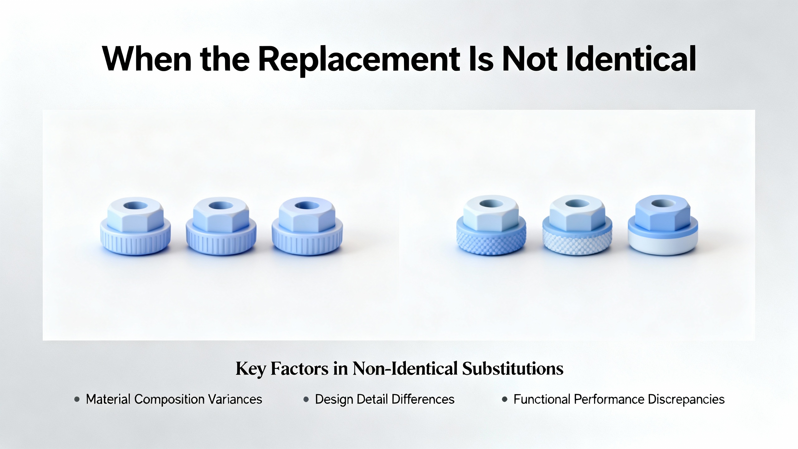
You start by verifying that the replacement module truly matches the original. That means checking the exact B&R order number, not just the general family, and ensuring the same electrical specifications. This is essential even if the module is part of a standardized rack like X20, because different slices can look similar while having different capabilities or channel counts.
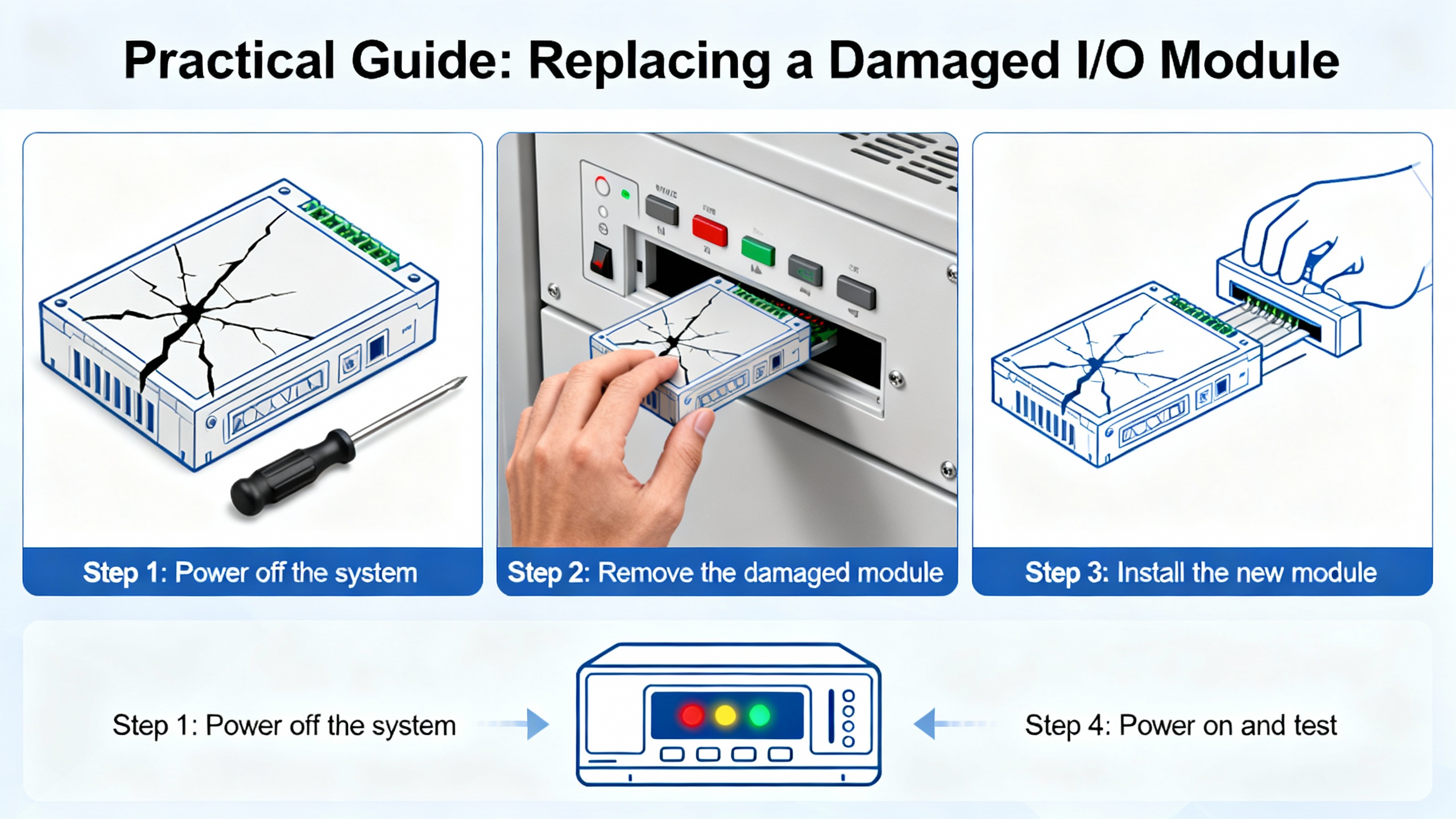
With the correct module in hand, the mechanical replacement is straightforward in most panel layouts. The line should be stopped, power to the rack removed, and correct lockout/tagout applied. Confirm that field wiring is labeled or documented so it can be reconnected exactly as before. Then remove the damaged module from its base or backplane and seat the new module in the same position, using the same base module and backplane.
From the controllerŌĆÖs perspective, nothing in the project has changed. The hardware configuration in Automation Studio still points to a specific module type at that slot, with defined firmware and channel mappings. At the next power-up, the PLC will detect the new module. Based on the B&R Community explanation of module firmware handling, the controller then compares the installed firmware with the project-defined version and, if needed, upgrades or downgrades the module firmware automatically within the allowed range. Since the project already knows that slot as an X20 slice of a particular type, the channel mapping stays intact.
Under those conditions, replacing a damaged X20 module with an identical type typically does not require project changes or a software update by the technician on site. The firmware and configuration are driven by the existing project. That said, it remains good practice after the swap to observe the controllerŌĆÖs startup behavior, check for error LEDs, and verify in Automation StudioŌĆÖs online view that the module appears healthy and that the input and output channels behave as expected.
Real life is often messier. Legacy modules can be hard to source, or the warehouse may only have a newer revision or related type available.
Corso Systems describes how sourcing legacy Allen-Bradley hardware sometimes forces engineers to accept different processor revisions and then modify the program. B&R is no different on older platforms. The MrPLC discussion about upgrading B&R 2005 projects to X20 hardware outlines an upgrade path that crawls through specific Automation Studio versions because of major changes between version families. That conversation underscores a key point: when you cannot match the original hardware closely enough, you are no longer doing a simple module replacement. You are in migration territory.
On B&R, using a different module type or channel density usually means updating the hardware configuration in Automation Studio, potentially using the ŌĆ£Include Legacy ModulesŌĆØ filter to find a compatible replacement or redesigning the I/O layout. Channel names can change, and process variable mappings may need to be redone. For motion or safety-related modules, differences in features and timing can have wider implications for logic and safety functions.
Firmware can also limit your options, though B&RŌĆÖs protection mechanisms are designed to block unsafe combinations. If you insert a much older module that does not meet the minimum firmware expectations encoded in the hardware definition, the module may refuse to accept a downgrade, as described in the B&R Community thread. In such cases, you may need to update the projectŌĆÖs firmware configuration or consult B&R support to determine an approved combination.
The practical rule is simple. If the replacement is not the same catalog number and feature set, do not assume the project will ŌĆ£just work.ŌĆØ Treat it as an engineering change, not a maintenance swap, and schedule the testing, documentation updates, and stakeholder communication that go with that responsibility.
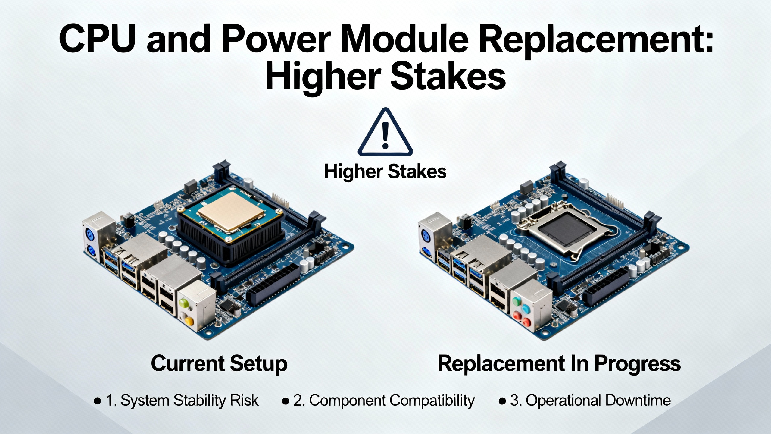
Replacing a CPU or power supply module is a more delicate operation than swapping an I/O slice.
RGB ElektronikaŌĆÖs overview of CPU modules makes it clear that symptoms such as the controller remaining stuck in STOP or ERROR, an inability to connect over Ethernet or USB, persistent program loss after power cycling, or visible physical damage strongly suggest a faulty CPU. After verifying that the power supply, I/O modules, and firmware are all known good, CPU replacement is often the next logical step.
B&R-specific practice, as described in PLC Talk discussions, typically uses compact flash cards that contain system binaries and sometimes source archives, along with redundant partitions for resilience. In many cases, recovering from a CPU hardware failure is as simple as moving the compact flash card into a new, identical CPU module. The new hardware then boots the existing software environment and re-establishes communication with the I/O and drives. This is analogous to swapping a PC while keeping the hard drive.
Power supply modules deserve equal respect. On B&R rack systems, specialized supply modules such as PS2100 for output power or PS3300 for logic power are used where many modules are present. Engineers on MrPLC emphasize checking internal power consumption and designing isolated I/O power groups so that cutting twenty-four volt output power, for example during an emergency stop, does not drop the CPU or critical logic power. When a power supply module fails, replacing it with the wrong variant or without understanding which groups it feeds can introduce subtle safety issues, like outputs remaining energized when they should be dead or vice versa.
For both CPU and power modules, there is also the repair versus replace decision. RGB Elektronika notes that remanufacturing or reconditioning a CPU can be cheaper and faster than sourcing a new one, especially for older or discontinued models. New modules offer warranty and the latest firmware, which can be crucial for production-critical systems. The right choice depends on part availability, downtime tolerance, and the age of the platform.
Legacy B&R 2005 systems are still in service in many plants, and replacing modules on those platforms can expose you to unexpected software issues.
A MrPLC thread from 2015 explains that upgrading a B&R 2005 project to X20 hardware relies heavily on Automation Studio version compatibility. If the original program was created in Automation Studio, there is an automatic upgrade path, but it must follow specific version steps. Engineers often open projects in Automation Studio 2.7 first, then in a 3.x version, and only after that in the latest release. Major changes between Automation Studio 2.x and 3.x, and a smaller but still relevant jump from 3.x to 4.x, make this path important.
There are other pitfalls. Motion libraries such as NCX and older HMI variable-linking formats may not upgrade cleanly, leading to lost tag links or broken motion functions. The recommendation from practitioners is to always back up, install Automation Studio under a straightforward path such as C:\BrAutomation for stability, and avoid certain operating systems that have historically caused issues with older Automation Studio versions.
If you are called in to replace a module on a B&R 2005 system and you discover that a simple one-for-one swap is not possible because the part is obsolete or the project needs migration, it is better to be honest about the scope. In those situations, a modular modernization plan, including project upgrades through the recommended Automation Studio versions and careful testing of motion and HMI behavior, is safer than trying to force a quick fix.
Several sources emphasize that the biggest risk in legacy PLC support is often not the hardware but the knowledge gap. Corso Systems argues that plants should close that gap by proactively training staff on legacy hardware before emergencies, documenting procedures for going online with processors, managing I/O and logic, and troubleshooting, and updating electrical and I/O drawings to reflect reality.
For B&R in particular, there is a rich ecosystem of community knowledge. The B&R Community forum threads on module visibility, firmware handling, and error log extraction show how quickly a specific problem can be resolved when you can describe it clearly and share logs. Third-party blogs such as DMCŌĆÖs Automation Studio series and practitioner forums like PLC Talk and MrPLC add practical context on version compatibility, hardware design, and migration patterns.
From an on-site engineerŌĆÖs perspective, the best recipe for predictable module replacement combines disciplined backups, clear documentation of hardware and firmware versions, familiarity with Automation StudioŌĆÖs hardware configuration and view options, and a readiness to consult vendor support or community resources when you hit edge cases such as firmware minimums or legacy migrations.

In most B&R systems, if you replace a damaged I/O slice with an identical model in the same slot and the existing project already defines that hardware in the physical view, no software change is required. The project still points to the same module type and channel mapping, and the PLC will align the module firmware at boot according to the projectŌĆÖs configuration. You should still verify that the controller comes to RUN without errors and that the I/O behaves as expected.
B&RŌĆÖs design, as described in community discussions, is to treat the project as the authority on module firmware. On boot, the PLC checks for mismatches and automatically upgrades or downgrades module firmware to match the project-defined version. Some modules enforce a minimum firmware version and will block downgrades below that threshold. In those cases, the module remains on a compatible newer version, and the project usually does not need to be changed.
If an identical replacement is not available, you should treat the job as an engineering change, not just maintenance. That typically means selecting a supported alternative in Automation StudioŌĆÖs hardware catalog, possibly using ŌĆ£Include Legacy ModulesŌĆØ to reveal more options, updating the physical view, adjusting process-variable mappings, and thoroughly testing behavior. If the platform is very old, as with B&R 2005 systems, you may need to plan a broader migration to X20 hardware following the recommended Automation Studio upgrade path.
CPU replacement is strongly indicated when there is clear physical damage, persistent error states that are not resolved by verified-good power and I/O, repeated loss of the project on power failure, or complete inability to connect over standard interfaces. RGB Elektronika recommends weighing reconditioning versus buying new based on part availability, required speed of restoration, and the criticality of the application. For modern, production-critical lines, new CPUs with full manufacturer support are often the safest choice.
Replacing B&R PLC modules does not have to be a gamble. When you respect the way B&R manages firmware, pay attention to how hardware is defined and displayed in Automation Studio, and pair that with disciplined backups and honest diagnostics, most module swaps become predictable, low-drama operations instead of emergency experiments.


Copyright Notice © 2026 mooreautomated.com All rights reserved,Moore Automated is not an authorized distributor or representative of the manufacturers featured on this website. Brand names and trademarks featured are the property of their respective owners.


Leave Your Comment