


MP 3009X
Get A Quote
When a CompactRIO chassis boots and some or all C Series modules refuse to show up in NI Measurement & Automation Explorer (MAX) or a LabVIEW project, the line does not care that it is ŌĆ£just a detection issue.ŌĆØ From the operatorŌĆÖs point of view, an undetected module looks exactly like a broken sensor, a dead controller, or a stalled production cell.
In real deployments, I have seen module detection failures cause hours of downtime because the problem sat at the intersection of networking, drivers, and hardware limits rather than in one obvious place. National Instruments documentation, case studies from integrators such as Apex Waves and Viewpoint Systems, and NIŌĆÖs own known-issues lists all show the same pattern: most ŌĆ£missing moduleŌĆØ problems are preventable if you approach them methodically and respect the platformŌĆÖs limits.
This article walks through how CompactRIO detects controllers and modules, what typically goes wrong, and how to get modules back online quickly and safely using the same steps I rely on when I am standing next to a dead panel with production managers watching the clock.
Before troubleshooting, it helps to be clear on what ŌĆ£detectionŌĆØ means in a CompactRIO system. CompactRIO is NIŌĆÖs rugged, modular embedded platform that combines a realŌĆætime controller, an FPGA backplane, and C Series I/O modules. According to NI and integrators such as Apex Waves, detection happens in several stages.
First, the CompactRIO controller must appear as a remote system in NI MAX. That step relies on basic networking, IP configuration, and the NIŌĆæRIO server accepting remote connections. If the controller never shows under Remote Systems in MAX, you will not see any modules later.
Second, after the controller appears in MAX and has the correct software stack installed, LabVIEW uses the ŌĆ£Targets and DevicesŌĆØ dialog to add that controller into a project. NIŌĆÖs knowledge base recommends creating or opening a LabVIEW project, rightŌĆæclicking the project root, and choosing ŌĆ£New ┬╗ Targets and DevicesŌĆØ to add the CompactRIO controller as a target.
Third, LabVIEW queries the chassis for installed C Series modules. NI documentation describes a prompt labeled ŌĆ£Discover C Series Modules?ŌĆØ and recommends clicking Discover so LabVIEW can automatically scan the chassis and populate modules under the CompactRIO target in the project tree.
If any of those three stages fails, you will see some flavor of ŌĆ£controller not detected,ŌĆØ ŌĆ£modules are missing,ŌĆØ or ŌĆ£module mismatchŌĆØ errors. The following sections break those stages down and tie them to specific NI troubleshooting guidance.
How you program CompactRIO changes how modules are discovered and managed. NIŌĆÖs documentation distinguishes two main programming modes for a controller added into LabVIEW.
In LabVIEW FPGA Interface mode, you explicitly program the FPGA fabric, which gives you fineŌĆægrained control over timing and custom I/O behavior. NIŌĆÖs guidance is to choose this mode when you need custom FPGA behavior and highŌĆæprecision timing control. This mode is also the escape hatch when you hit some Scan Interface limits, especially for specialty digital resources.
In Scan Interface mode, the NI Scan Engine periodically reads and writes module channels, and you access I/O using shared variables or Scan Engine nodes without touching the FPGA. NI describes Scan Interface as better suited for simpler, scanŌĆæbased I/O access where hard realŌĆætime timing at the FPGA level is not required.
One NI errorŌĆæcode reference notes that specialty digital modules only support a finite number of ŌĆ£specialty digitalŌĆØ slots when using Scan Interface. For example, NI calls out error codes indicating that only two slots can be configured as specialty digital I/O in Scan Interface mode, and recommends adding an FPGA target and using LabVIEW FPGA Interface mode if you need more than that. On site, that mapping from an error code to ŌĆ£you are hitting a mode limitation, not a bad moduleŌĆØ is crucial.
The tradeŌĆæoff is simple. Scan Interface offers quick setup and automatic detection, but with tighter limits and less control. FPGA Interface requires more engineering effort but lets you work around some of those limits and gain better control over timing and resource usage. Keeping that in mind helps you interpret certain detectionŌĆærelated error codes correctly.
When nothing appears under Remote Systems in NI MAX, you are not yet at a module problem. You are at a connectivity and discovery problem. NIŌĆÖs knowledge base on ŌĆ£NI network devices not showing or not recognized in MAXŌĆØ lays out a practical sequence that maps very well to what I do in the field.
Start at the hardware and power level. Verify against the device user manual that the controller has the correct supply voltage and that power LEDs are normal. Check the Ethernet port link and activity indicators; if they are dark or not blinking, swap the Ethernet cable. You cannot troubleshoot software if the link is physically down.
Next, simplify the host PCŌĆÖs network environment. NI explicitly recommends disabling all but the primary network adapter and turning off WiŌĆæFi, especially on laptops, when you connect directly to an Ethernet target. Multiple active adapters cause routing confusion that makes autoŌĆædiscovery unreliable.
Then confirm addressing. If the controller is on a network with a DHCP server, NI advises checking with the network administrator that there are available addresses on the subnet and that the relevant switch ports are not blocked or filtered. If the device must be added manually to a DHCP network, coordinate with IT to reserve and assign an address.
From the NIŌĆæRIO side, open NI MAX on the host and ensure remote access is allowed. NI documentation describes going to the NIŌĆæRIO Settings under the Tools menu and adding a wildcard such as an asterisk under remote device access so that all remote systems may access RIO devices. Without that, the controller can sit on the same subnet and still not show up.
Once basic settings look plausible, test connectivity directly. NI suggests using ping to check whether the controller responds when it is on the same network as the host. If the CompactRIO responds to ping, but still does not appear in MAX, NI notes that reŌĆæimaging the host computer or repairing the NI System Configuration stack can help in some cases.
If the controller appears in MAX but shows a disconnected state, NI recommends resetting or repairing the MAX configuration database and, where applicable, reformatting the realŌĆætime controller image using official procedures. That step clears corrupted configuration data that can prevent proper discovery.
Finally, NI introduced a Remote Systems Discovery Troubleshooter in NI System Configuration 15.0, accessible in MAX by rightŌĆæclicking Remote Systems and choosing the discovery troubleshooter. NI instructs engineers to install the latest NI System Configuration, restart the PC, and then follow the wizard carefully. The tool automates several of the earlier checks and suggests additional steps tailored to the current configuration. The 15.0 version only supports English text and English LabVIEW installations by NIŌĆÖs own note, which was later improved in NI System Configuration 16.0.
Throughout this process, do not ignore the Windows firewall. NI gives concrete steps for Windows XP and Windows 7 to add Measurement & Automation (MAX) as an allowed program in the firewall settings, ensuring that discovery traffic is not silently blocked.
Once the controller is visible in MAX and added to a LabVIEW project, the next failure mode is that one or more C Series modules do not show up under the chassis, or show as disconnected or mismatched compared with the physical hardware. NIŌĆÖs guidance on detecting CompactRIO systems in LabVIEW and the CompactRIO error code reference both describe common root causes.
In the LabVIEW project, NI recommends explicitly running the Discover C Series Modules process after adding the controller. If that discovery dialog is skipped, modules simply will not appear in the project tree, even though they are physically present. That is the first easy fix.
If discovery runs but some modules remain missing or mismatched, NIŌĆÖs CompactRIO error code documentation groups related errors in the ranges around 65400 to 65538. These cover situations where the detected module does not match the expected module configured in software, a module is missing, or a module is not supported by the installed version of LabVIEW or NIŌĆæRIO. In some cases, NI notes that an error can indicate that an FPGA VI is already running and controlling the module, preventing other interfaces from attaching.
The recommended actions are straightforward but important. Ensure that the slot configuration in LabVIEW matches the physical module layout in the chassis. Do not assume the project is correct; compare each slot number and module type against what is actually installed. Then verify that the module type is supported by the installed driver set and LabVIEW version. Apex Waves explicitly advises aligning the CompactRIO software packages on the controller with the LabVIEW development version, and NIŌĆÖs separate article on avoiding CompactRIO software compatibility issues highlights the need to respect NIŌĆÖs version compatibility tables.
To check software support, NI and Apex Waves recommend using NI MAX and the ŌĆ£Add/Remove SoftwareŌĆØ dialog under the CompactRIO controller to confirm that LabVIEW RealŌĆæTime, LabVIEW FPGA, and the CompactRIO driver corresponding to your development version are installed. If a module is absent from the list of supported C Series modules after that, there is a high chance you are dealing with an unsupported hardwareŌĆōsoftware combination.
NIŌĆÖs knownŌĆæissues documentation adds another nuance. When using RealŌĆæTime Scan mode, accessing properties of modules that have not yet been deployed can produce an error stating that the CompactRIO system could not resolve the module URL, indicating that the system does not consider the module fully deployed to the target. NI recommends deploying all modules to the controller before trying to read or write module properties.
Taken together, the field pattern matches NIŌĆÖs documentation: unresolved modules usually point to skipped discovery, slot mismatches, or missing driver support, not to an immediate hardware failure.
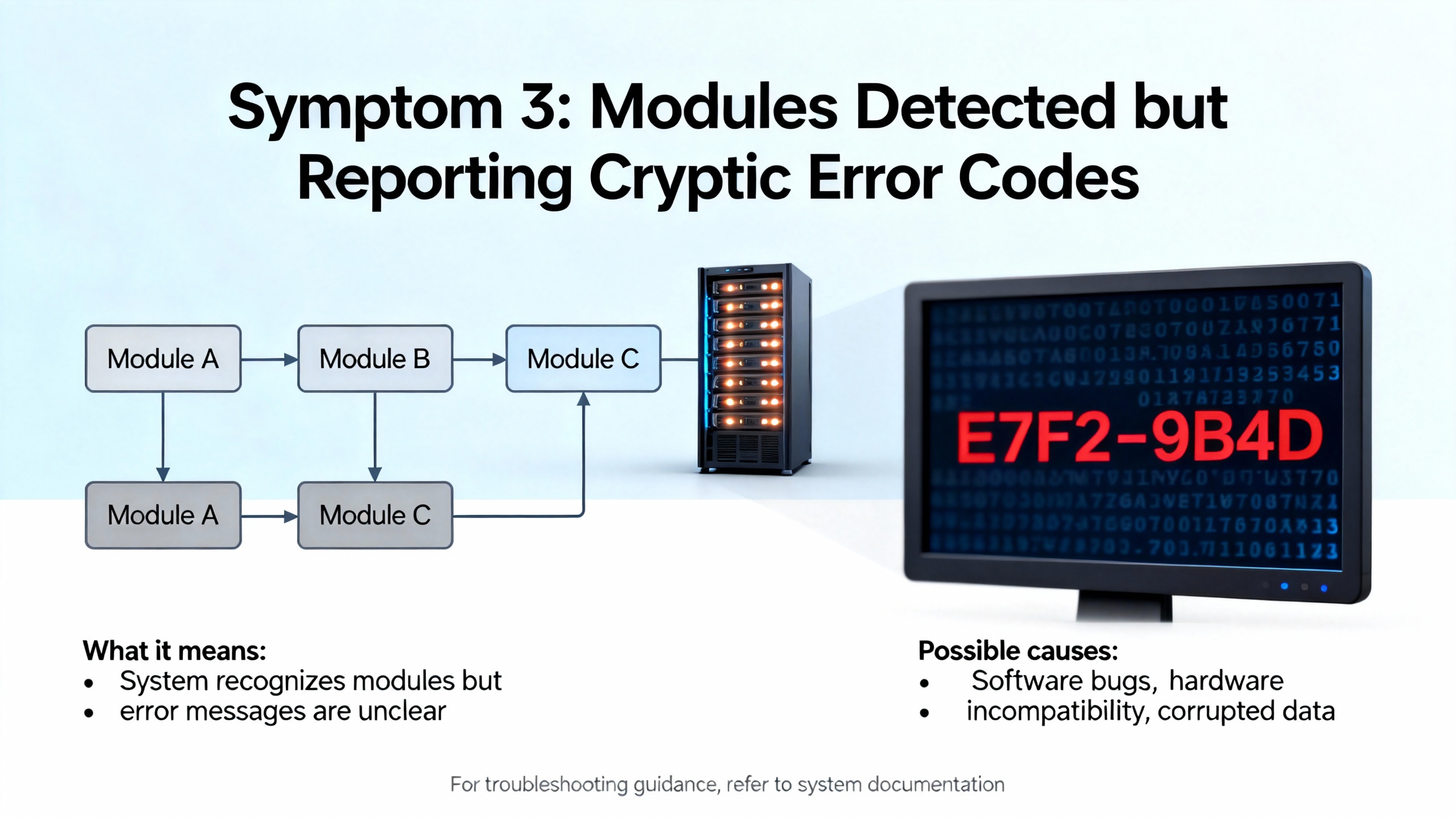
Sometimes the controller and modules appear correctly in MAX and LabVIEW, but an I/O channel throws error codes as soon as it is used or behaves intermittently. NIŌĆÖs CompactRIO and C Series error code tables are essential here, because they categorize failures by resource type and often suggest concrete remedies.
Digital I/O conflicts are one frequent source of trouble. NI groups several error codes that occur when a single digital line is accessed by multiple node types, when duplicate terminals exist in an FPGA I/O node, or when Digital Output and Digital Port Output nodes both try to use the same underlying resource. The recommended mitigation from the NI error reference is to restrict each hardware line to a single access type, remove duplicate terminals from FPGA I/O nodes, adjust the number of synchronizing registers where relevant, and avoid using the ŌĆ£Never ArbitrateŌĆØ option when multiple pieces of code share the same resources. In practice, that often means cleaning up legacy code where different developers added overlapping I/O nodes.
Clocking and timebase issues are another category that can masquerade as detection problems. NI documents error codes indicating invalid module timebase settings, unknown master timebase sources, unsupported synchronization schemes, or invalid topŌĆælevel FPGA clocks. The guidance is to configure all modules that must share timing to use a common timebase, to rely on onboard clocks for some chassis, and to enforce a 40 MHz topŌĆælevel FPGA clock when required by specific hardware combinations. If a module technically appears but refuses to run, a bad clock configuration is high on the suspect list.
SensorŌĆæspecific errors also matter. NIŌĆÖs error listings identify problems such as unsupported TEDS access, communication timeouts with modules, missing TEDS sensors, open current loops, open thermocouples, and commonŌĆæmode voltages that fall outside supported ranges. The fixes are not glamorous but they are reliable: validate that the module truly supports the TEDS features being used, confirm sensor compatibility, and recheck wiring and terminal connections channel by channel. An open thermocouple or loop will cause the module to report diagnostic errors rather than quietly continuing.
Communication and timing problems show up when loops running on the CompactRIO do not keep pace with module data rates. NI associates error codes in the 65536 to 65541 range with module communication failures, timeouts, missed input data points when application loops lag behind, and incorrect communicationŌĆæmode state. NIŌĆÖs recommendations focus on ensuring that loops execute fast enough and that the appropriate communication mode is explicitly started and stopped. When I am in a plant debugging such issues, I often begin by measuring loop timing and, if necessary, splitting heavy work into slower parallel loops so the I/O loop can keep up.
Together, these categories underscore a key point: once the module is visible, most problems move from discovery into resource conflicts, timing, or wiring. Interpreting error codes through NIŌĆÖs documentation turns ŌĆ£crypticŌĆØ messages into actionable steps.
Not all ŌĆ£module problemsŌĆØ originate in the module. NIŌĆÖs error code tables include a large set of codes related to file systems, SD cards, and power that can cause a CompactRIO system to behave as if a module or data logging function is failing when the underlying issue lies elsewhere.
For storage, NI documents codes for unmountable drives, corrupt or missing partitions, invalid drive handles, attempts to mount an already mounted drive, fileŌĆænotŌĆæfound situations, illegal open, close, read, or write modes, and limits such as only one file open at a time on certain modules. Additional codes signal full file systems, exceeding a limit of root directory entries, SD card doors being open, and invalid or unsupported file system formats such as nonŌĆæFAT16 media where FAT16 is required. The recommended remedies from NI include running file system checks such as CHKDSK on affected drives, ensuring that SD cards are formatted with supported file systems, closing files before certain operations, and verifying both card insertion and door status.
On the power side, NI lists error codes that report supply voltage outside acceptable ranges, channels entering overcurrent or combined overcurrent and overvoltage protection modes, and fault conditions detected at terminals. The guidance is to check supply voltages against specifications, search for shorts or failed external devices attached to module outputs, and correct any overŌĆærange voltages or currents before reŌĆæenabling the channels.
From a troubleshooting standpoint, these categories matter because a module may stop acquiring or logging data not because the detection logic failed but because the system is protecting itself from power or storage problems. Being familiar with these error families helps you avoid replacing a healthy module when the real problem is an SD card formatted incorrectly or an overloaded external circuit.
NIŌĆÖs documentation on network device discovery and known issues around CompactRIO highlight some less obvious scenarios that can cause module detection or access to fail.
One example involves controllers whose IP address is reset to an invalid value such as 0.0.0.0. NI notes that some IT security tools will block traffic from such addresses. The suggested recovery is to connect the controller to a network segment that provides a DHCP server, allowing it to acquire a valid address, after which you can reconfigure it in MAX.
Another class of problems involves how NIŌĆÖs tools themselves behave. NIŌĆÖs knownŌĆæissues lists describe cases where measurement tools or technical reports generated by MAX on Linux realŌĆætime controllers no longer automatically include certain configuration files such as nirio.ini, which stores RIO server remote access settings. When you are auditing why a particular host cannot access a CompactRIO or certain modules, you may need to retrieve that configuration file directly from the controllerŌĆÖs file system instead of relying on the autoŌĆægenerated report.
These details are not glamorous, but they explain why a system that ŌĆ£should workŌĆØ based on a quick visual inspection can still ignore a module in a real plant network.
The best time to fix module detection failures is before the system ships. Several sources, including NI guidance on preventing software compatibility issues, an NI article on CompactRIO known issues, and a Viewpoint Systems article on NI hardware compatibility, converge on the same point: discipline around software versions and hardware baselines pays off.
NI emphasizes keeping LabVIEW, LabVIEW RealŌĆæTime, LabVIEW FPGA, and CompactRIO or NIŌĆæRIO device drivers in compatible combinations according to NIŌĆÖs published compatibility tables. In practice, that means choosing a specific LabVIEW version and then installing the matching CompactRIO driver packages and realŌĆætime modules both on the development PC and on every controller. Apex Waves explicitly recommends this matchedŌĆæversion approach when configuring CompactRIO systems in LabVIEW.
A common practice NI advocates is to standardize on a tested reference image for each CompactRIO model. That image includes the controllerŌĆÖs operating system, all required drivers, and any base configurations. You then replicate that image to every controller of the same type, rather than handŌĆæconfiguring each one. NI and community experiences also warn that imaging tools have boundaries; for instance, engineers have reported that NIŌĆÖs Replication and Deployment utility works reliably for the realŌĆætime application but can be less consistent with FPGA bitfiles, and that images created from hardware missing certain modules can fail to deploy properly to targets that expect those modules. The lesson is to build images on hardware that matches the deployed configuration as closely as possible.
NIŌĆÖs knownŌĆæissues lists specifically caution against uninstalling and reinstalling CompactRIO software stacks on targets with NIŌĆæDAQmx in some versions because it can corrupt module and chassis aliases, causing confusing warnings in MAX. NIŌĆÖs recommended pattern is to reformat the controller and perform a clean reinstall instead of layering uninstalls and reinstalls. That extra discipline avoids subtle alias and detection problems later.
Viewpoint Systems describes broader hardware compatibility lessons that also affect detection. Selecting C Series modules with appropriate signal levels, ensuring controller processing capacity is sufficient for required data rates, and planning for synchronization and timing technologies such as Time Sensitive Networking are all part of this. While these topics reach beyond pure detection, the practical takeaway is that many ŌĆ£modules not behaving as expectedŌĆØ reports originate in underŌĆæpowered controllers, misŌĆæmatched modules, or unplanned timing requirements, not in detection logic alone.
By combining NIŌĆÖs softwareŌĆæcompatibility guidance with careful image management and conservative hardware choices, you dramatically reduce the number of times a module surprises you by disappearing in the field.
Putting the vendor recommendations and field experience together, it is useful to think in terms of a consistent workflow whenever modules go missing. The idea is to move from the outer layers inward, only advancing once the previous layer is clearly healthy.
Start with physical power and network links. Confirm that controller power rails are in spec and that Ethernet link and activity indicators look normal. Swap cables if necessary. If connectivity is pointŌĆætoŌĆæpoint from a laptop, disable WiŌĆæFi and extra network adapters to avoid routing confusion.
Once the link is up, focus on IP configuration and NIŌĆæRIO access. Use NI MAX to confirm that the controller appears under Remote Systems. If not, check DHCP availability, work with IT to ensure switch ports do not block traffic, and ensure that the NIŌĆæRIO server on the host allows remote access. Where necessary, use ping tests as NI suggests, and consider the automated Remote Systems Discovery Troubleshooter to accelerate the early checks.
When the controller appears, validate the software stack. In MAX, use Add/Remove Software to verify that the correct versions of LabVIEW RealŌĆæTime, LabVIEW FPGA, and the CompactRIO driver are installed, as Apex Waves and NI recommend. Align these versions with your LabVIEW development environment according to NIŌĆÖs compatibility tables.
Next, move into LabVIEW. Add the CompactRIO target to your project using the Targets and Devices dialog, select the appropriate programming mode (Scan Interface or LabVIEW FPGA Interface) based on your timing and flexibility needs, and run the C Series module discovery process. Make sure the projectŌĆÖs slot configuration matches the actual chassis layout.
If modules appear but report errors, consult NIŌĆÖs CompactRIO and C Series error code documentation. Interpret digital I/O conflicts, timebase errors, sensor diagnostics, communication timeouts, power faults, and file system codes in light of NIŌĆÖs recommendations, and correct wiring, timing, or resource conflicts before suspecting hardware failure.
Finally, once the system is running, document the working configuration. Capture controller software versions, installed driver sets, module lists, and any nonŌĆædefault configuration. NI and independent integrators both emphasize that this kind of documentation makes future recoveries and new deployments far more predictable, and keeps module detection problems from reappearing every time you replace a controller.
To summarize these relationships, the following table maps common categories to symptoms and typical fixes based on NI and integrator guidance.
| Category | Typical symptom | Primary fix (source) |
|---|---|---|
| Controller not discovered | CompactRIO absent or disconnected in MAX | Verify power, Ethernet LEDs, DHCP, NIŌĆæRIO settings, firewall, and use discovery troubleshooter (NI) |
| Modules missing in LabVIEW | Chassis visible but slots empty or mismatched | Run module discovery, align slot map with hardware, install compatible drivers (NI, Apex Waves) |
| Digital I/O resource conflicts | Errors when using shared digital lines | Use a single access type per line, remove duplicates, avoid ŌĆ£Never ArbitrateŌĆØ (NI error reference) |
| Timebase and clock misconfig | Modules present but fail on run or sync | Share valid timebase, use required topŌĆælevel FPGA clock, rely on supported clocks (NI) |
| Sensor and TEDS issues | OpenŌĆæcircuit errors, TEDS timeouts, outŌĆæofŌĆærange voltage diagnostics | Verify module capabilities, sensor compatibility, and wiring (NI) |
| Communication and loop timing | Missed samples, timeouts, data overrun errors | Speed up I/O loops, separate heavy tasks, correct communication mode state (NI) |
| File system or SD card errors | Logging failures, unexpected file errors, module data appears to ŌĆ£vanishŌĆØ | Run CHKDSK, ensure FAT16 where needed, manage open files, check card door and format (NI) |
| Power and protection faults | Channels shut down, modules stop driving outputs or reading inputs | Check supply voltages, search for shorts or failed loads, correct outŌĆæofŌĆærange conditions (NI) |
| Software compatibility issues | Supported module not recognized, alias warnings, odd deployment behavior | Align LabVIEW and driver versions, use golden images, reformat controllers before reinstall (NI) |
NIŌĆÖs compatibility guidance and integrator case studies show that two controllers that look identical on paper may run different operating system images, driver versions, or LabVIEW runtimes. A module recognized on one unit can be flagged as unsupported on another if their software stacks differ. Building and deploying a single, tested image per controller family avoids that drift and keeps module detection consistent.
NI positions the Scan Interface as the simpler choice for many systems, and it integrates well with module autoŌĆædiscovery. However, NIŌĆÖs error code reference shows clear limits, such as the small number of specialty digital slots supported. When you hit these limits or need tighter timing and resource control, NI recommends moving to LabVIEW FPGA Interface mode, even though it requires more design effort.
NIŌĆÖs error code documentation separates detectionŌĆælevel problems from sensorŌĆælevel diagnostics. If a module or slot is completely missing from MAX or LabVIEW, focus first on networking, software versions, and slot configuration. If the module appears but channels report open circuits, invalid TEDS, or outŌĆæofŌĆærange voltages, NIŌĆÖs guidance points toward sensor compatibility and wiring. Using those categories, you can quickly decide whether to reach for a screwdriver or a configuration dialog.
In the field, robust CompactRIO systems come from treating module detection as a disciplined process rather than a oneŌĆætime nuisance. If you consistently align software versions, respect hardware limits, follow NIŌĆÖs discovery workflow, and read error codes as design feedback instead of noise, module detection stops being a mystery and becomes another reliable part of your automation toolkit.


Copyright Notice © 2026 mooreautomated.com All rights reserved,Moore Automated is not an authorized distributor or representative of the manufacturers featured on this website. Brand names and trademarks featured are the property of their respective owners.


Leave Your Comment