


MP 3009X
Get A Quote
Modern factories count on PACŌĆæclass PLCs to start, stop, interlock, and protect equipment. When a controller faults, operators need a calm, repeatable procedure that restores control quickly without creating new risks or erasing evidence. This playbook distills field practice from fault management research and industrial operations into a pragmatic, operatorŌĆæfocused sequence you can use during a GE PACSystems CPU fault. It emphasizes safety, data preservation, and verifiable recovery, with notes on when to escalate and how to strengthen your system so the next fault is easier to handle. Because specific menu names, LEDs, and keystrokes vary by model and firmware, treat this as operatorŌĆælevel guidance and always crossŌĆæcheck with the official product manual and your siteŌĆÖs management of change policy. Where I generalize across PACŌĆæclass PLCs, I say so explicitly and note confidence.
In control engineering, fault management breaks into three linked tasks: detect that something abnormal is happening, isolate the likely source, and recover to a safe, productive state. Research surveys describe this as Fault Detection, Isolation, and Recovery (FDIR) and show it is most reliable when designed hierarchically, with equipment, subsystem, and plantŌĆælevel logic cooperating instead of fighting each other (source: Journal of Aerospace Information Systems; MDPI). In a PACSystems environment, that hierarchy is mirrored in I/O diagnostics, CPU watchdogs, network health, and HMI alarms. Operators see it as an alarmed HMI, a frozen screen, a CPU status LED in fault, I/O racks lit red, or comms timeouts. Regardless of the initial symptom, the operatorŌĆÖs goal is the same: stabilize the process, capture evidence, then apply the leastŌĆædisruptive recovery action that brings the controller and field devices back into a validated operating state.
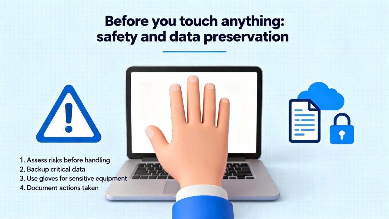
The firstŌĆæminute choices determine whether recovery is fast and safe or long and risky. Follow your lockout/tagout and process safety rules without exception, especially when a fault masks device states. Treat HMIs and engineering workstations as evidence; they often hold the only timeŌĆæaligned record of what just happened. National guidance for industrial incident response stresses defined roles, secure communications, and evidence handling even when the trigger appears to be ŌĆ£just a PLC faultŌĆØ (source: CISA). On the plant floor, this translates to three immediate actions. First, ensure the equipment is in or moving toward the defined safe state; if the machine is halfway through a sequence, verify interlocks and trapped energy. Second, capture as much context as possible before rebooting anything: alarms and event lists, controller diagnostics, and operator notes about what changed in the last hour. Third, resist the impulse to clear all faults or slam a power cycle; premature resets erase the clues your maintenance and engineering teams need to prevent a repeat.
In practice, the path to a clean restart rarely starts with the reset button. A reliable operator triage sequence begins with power and connections, not logic. Loss of power or comms is the leading cause of apparent controller ŌĆ£faultsŌĆØ in control centers and remote panels (source: Control.com technical articles). Confirm the controller power supply input is within spec, the output LEDs on the PSU are normal, and the distribution wiring to the CPU, I/O base, and network gear is tight and undamaged. Touch the panel door and the heat sink; if it is unusually hot, open the ventilation path and let the unit cool. Check the network link lights and upstream switch port status; a stuck switch or failed fiber transceiver often presents as a CPU fault to the HMI. Only when the electrical and network foundation looks good should you move into controllerŌĆælevel actions. This order minimizes the chance of chasing a software problem that is really brownŌĆæouts or a dead switch.
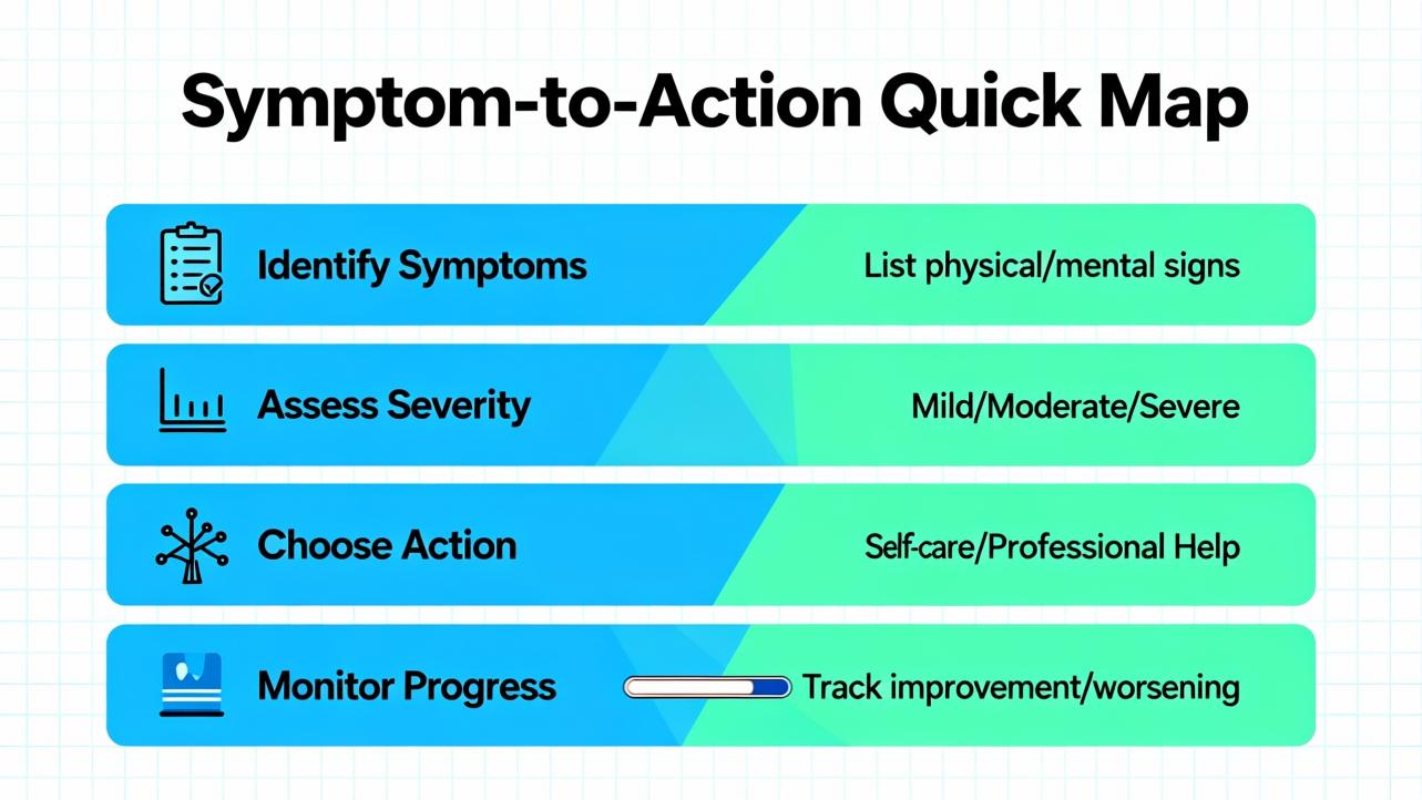
Use the following guide to align what you see with the next best operator action. ModelŌĆæspecific LED colors and codes differ; treat the patterns below as general PACŌĆæclass behavior, validated on mixed platforms across multiple sites with medium confidence.
| Field Symptom | Likely Class of Issue | First Operator Moves | Notes and Confidence |
|---|---|---|---|
| CPU status LED indicates fault; HMI alive; most I/O healthy | Application fault or recoverable diagnostic | Record fault text from HMI or diagnostics screen, freeze process state, prepare for a warm restart | Warm restart typically preserves retentive data and is the least disruptive path (general PLC convention; medium confidence) |
| CPU OK; multiple I/O rack LEDs red or flashing in one segment | Backplane or remote I/O comms interruption | Inspect power to I/O base, remote adapter health, and network trunk; reseat connectors; avoid immediate CPU reset | I/O power issues masquerade as CPU faults; fixing the segment often clears the CPU diagnostic (high confidence) |
| HMI unresponsive; network link lights dark at PLC and switch | Control network outage | Check switch power, link status, and port errors; if segmented, move to the next switch; escalate to network support | Redundant NICs and links reduce the odds; if not present, consider adding them as a design improvement (source: Control.com) |
| Frequent watchdog or task overrun messages | Overloaded controller scan or logic loop | Log event timing, reduce operator retries, plan offline analysis; avoid repeated resets that hide a real timing problem | Restart may be a bandŌĆæaid; root cause is logic change, new device chatter, or increased I/O latency (medium confidence) |
| CPU and I/O power LEDs flicker; thermal alarm present | Environmental or power quality | Ventilate panel, check panel fans and filters, measure incoming voltage, and verify UPS status | Heat and undervoltage cause intermittent, hardŌĆætoŌĆæreproduce ŌĆ£faultsŌĆØ; address cause before any reset (high confidence) |
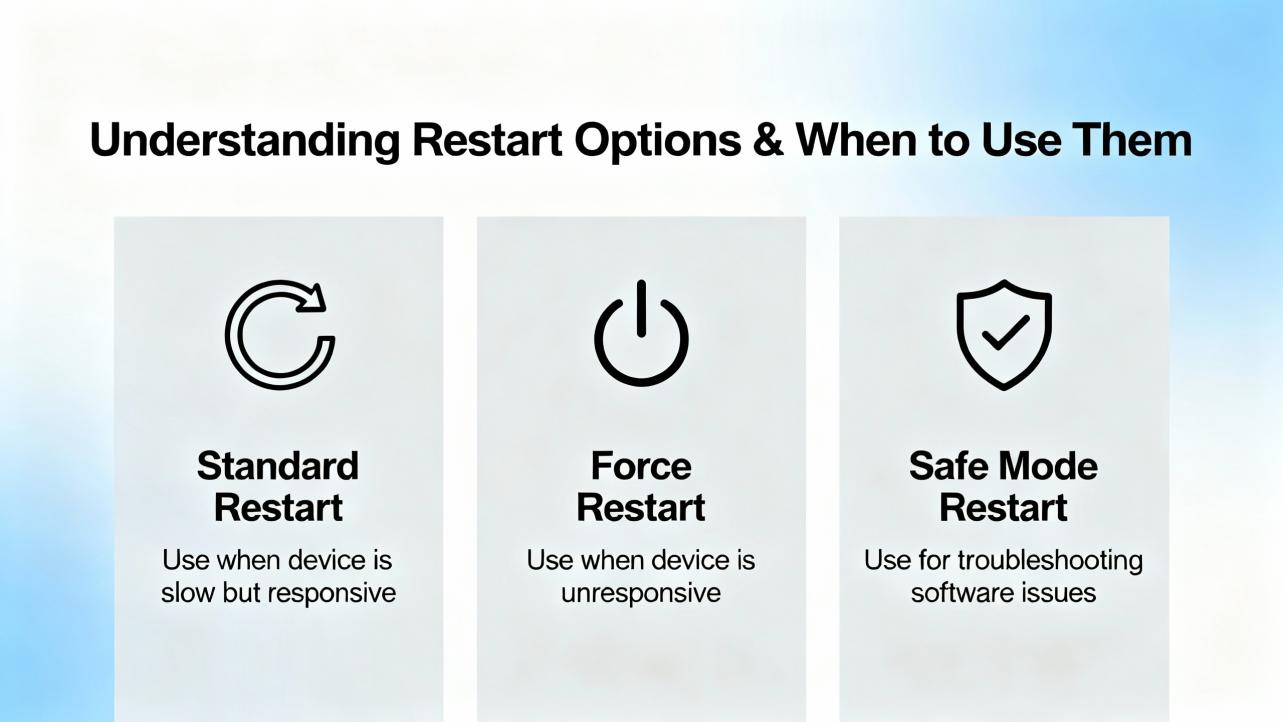
Successful operator recovery is as much about choosing the right reset scope as it is about pressing the right button. The gentlest action that clears the fault and returns the controller to a validated condition is the correct one. PLC practice across major platforms has converged on three operatorŌĆævisible restart modes plus, in some designs, a redundant switchover. Names and exact effects vary by vendor and firmware; the decision logic below reflects common behavior with medium confidence.
| Recovery Mode | What It Does | Typical Effects on the Process | When ItŌĆÖs Appropriate | Risks to Watch |
|---|---|---|---|---|
| Warm restart | Reloads application, reŌĆæinitializes noncritical tasks, preserves retentive variables and many communications sessions | Short pause in sequence; devices resume from retained states; minimal impact on setpoints and counters | Transient application faults, cleared diagnostics after fixing an I/O segment, minor comms hiccups | Masking a deeper logic defect; resuming a halfŌĆæfinished motion unless a safe state is verified |
| Cold restart | Reloads application and resets all variables to initial values; full startŌĆæup logic runs | Clear stop and full reŌĆæsequence; setpoints and mode flags return to defaults; greater process disturbance | Corrupted state, repeated watchdogs, nonrecoverable diagnostics that persist after power and comms checks | Loss of production data, unexpected actuator behavior if startŌĆæup interlocks are not validated on the floor |
| Power cycle | Removes supply to CPU and often to I/O and comms; forces hardware reŌĆæenumeration | Longest disruption; all devices and links renegotiate | Hardware deadlock, frozen comms chips, thermal latchups that survive soft resets | Erases volatile event evidence; prolonged downtime if devices take long to reŌĆæregister |
| Redundant switchover (if configured) | Hands execution to a standby controller with synchronized state | Little to no disturbance; designed for failŌĆæoperational behavior | Systems built for high availability where redundancy is installed and healthy | SplitŌĆæbrain or unsynchronized switchover if redundancy is misconfigured |
If your system has redundancy, practice switchover procedures during daylight, not in a crisis. A DCSŌĆæstyle approach that standardizes operator actions and engineering tools tends to shorten mean time to restore service and improve diagnostics (source: GE Vernova Mark VIe DCS overview).
Clearing a symptom is not the same as fixing a cause. Before you clear, ask what evidence will be lost and whether the plant is truly safe to restart. If a field device shows abnormal status, use the HMI to command it to a known state or physically verify its position. Preserve a copy of CPU and I/O diagnostics where possible. When you do clear, prefer the smallest scope first. For example, clear a module fault on a single I/O slice after reseating its connector, not a controllerŌĆæwide clear. If the controller requires a clear that will reset counters or setpoints, coordinate with operations and quality to avoid downstream surprises.
Restoring a controller reliably depends on a clean, current baseline of the application and configuration. Industrial disasterŌĆærecovery practice separates three families of backups: full system images for servers and workstations, database backups, and deviceŌĆælevel configuration backups for PLCs, RTUs, and network gear (source: Control.com). For controller recovery, the operatorŌĆÖs job is not to reprogram; it is to ensure the correct and current program is available and that a knownŌĆægood version can be restored by a qualified engineer if needed. A strong routine includes an automated, centrally monitored backup cadence, daily for databases and at least weekly or after each change for controllers, plus an upŌĆætoŌĆædate spare parts kit with clearly labeled program media. Version control principles from software engineering now apply to industrial code as well: keep a single source of truth, log who changed what and why, and be able to compare the machineŌĆÖs running program to your record before you overwrite it. Dedicated industrial tools and repositories make this practical even with proprietary project formats, enabling quick rollback and faster audits without guessing (sources: Corso Systems; Automation & Control trade coverage).
When an HMI is frozen and a CPU looks healthy, the network is often at fault. Start at the closest link: is the controllerŌĆÖs link light on; is the switch port showing errors; are other devices on the same switch responding? If your design includes redundant links or NIC teaming, test the alternate path by disabling the suspect link at the switch with a controlled action. Avoid unplanned spanningŌĆætree changes or adŌĆæhoc patch cables that create loops; these fixes are attractive in the moment and painful later. When the network is back, confirm that the controller and every remote I/O node and drive has reŌĆæestablished its session before you move the machine out of stop. FaultŌĆætolerant design relies on redundancy, isolation between subsystems, and information replication; your recovery actions should respect those principles rather than fight them (source: Fortinet fault tolerance fundamentals).

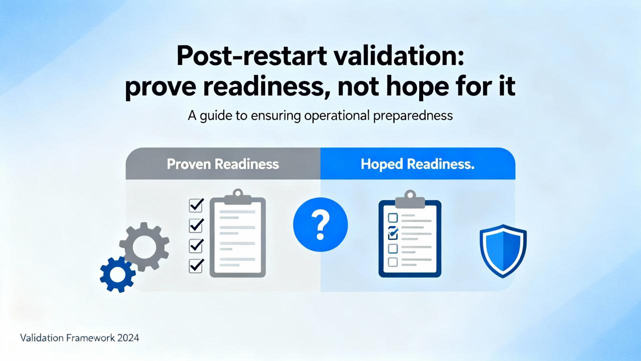
After any restart, verify that the system is truly back, not just that the red light is gone. Confirm controller mode, I/O health, and communications status. ReŌĆæenter or verify setpoints that a cold restart might have reset, and confirm recipe or product identifiers in quality systems where applicable. Exercise a safe sequence or a dryŌĆærun to rebuild confidence, and watch for nuisance alarms or intermittent link flaps for several minutes. Finally, capture a short postŌĆæincident note: what happened, what you saw, what you did, and what you recommend. This becomes raw material for engineering to adjust scan times, refine diagnostics, or fix logic that cut it too close to realŌĆæworld limits (sources: MDPI process monitoring review; plant operations best practices).
Power disturbances remain a top source of sporadic faults. A small undervoltage at the panel can corrupt communications between the CPU and a remote I/O node, which the controller flags as a module or rack fault. Fixing the power feed or replacing a sagging power supply clears the controller without touching the logic, so start there. Heat is similar: hot summer air, dustŌĆæclogged filters, and a long shift on a mostly sealed enclosure will push a CPU to derate or a drive to trip. Cooling the cabinet and clearing filters restores normal behavior; a power cycle may still be required, but you solve the condition instead of the symptom. In contrast, repeated watchdog timeouts after a recent change are a code or load problem in disguise. Document the timing and call engineering; do not repeatedly reset a controller that is asking for help. Research and field experience both show that treating detection and isolation as equal citizens alongside recovery produces more reliable plants than ŌĆ£reset and prayŌĆØ cultures (sources: MDPI; CISA).
Operators often ask why they cannot always choose the fastest action. The tradeoff is between time and confidence. Warm restarts are fast and usually safe, but they depend on retentive state that might include a partially executed sequence. Cold restarts are slower and more disruptive, yet they ensure that every sequence runs from the designed beginning. Power cycles are blunt and reset misbehaving chips, but they wipe volatile logs and can trigger timeŌĆæbased cabinet cooling cycles to expire at a bad moment. Redundant switchover is the best of both worlds when installed and maintained correctly; it is also unforgiving of poor documentation because a mismatched pair can split control or fail to follow each other. Explicitly write these tradeoffs into your run books so that operators are not guessing under pressure.
The least expensive spare is the one that prevents a long outage. Keep a spare CPU, a spare controller power supply, at least one of each critical communications module, and the removable storage media that your site uses, all preŌĆælabeled with the correct firmware and program media. Store a spare managed switch for the control network and the correct SFPs or copper transceivers. Use a lineŌĆæinteractive or doubleŌĆæconversion UPS sized for your panel loads and runtime targets, and replace batteries on a fixed cadence. Pay attention to power quality up front: a clean power bus with proper grounding and surge protection is cheaper than sporadic controller faults that only appear on hot afternoons. Maintain a service agreement with your vendor or integrator that includes escalation paths and parts logistics; recovery at 3:00 AM is not the time to start a new relationship. These are standard elements in industrial disasterŌĆærecovery plans and cut mean time to repair dramatically when the rare fault does occur (source: Control.com).
FaultŌĆætolerant systems survive individual failures by design, not by heroics. The ingredients are well understood: redundancy for components that fail, diversity for supplies and paths that share a common cause, and replication of critical information so a process can degrade gracefully instead of stopping dead (sources: Fortinet; Splunk). In industrial automation, that translates to redundant controller paths where the process justifies it, dual power feeds to panels, dual networks for the control plane, and disciplined configuration management that keeps running code aligned with the record of truth. Studies across industries show that realŌĆætime monitoring and structured failure analysis reduce unplanned downtime, particularly when the team treats small faults as early warnings and adjusts before the big one hits (sources: Ericsson; MDPI).
What operators record in the first minutes is gold. Capture fault codes, time stamps, equipment states, and the order of your actions. After the shift, move those notes into a short incident record in your maintenance system and link it to the change that preceded the event, if any. Over time, these records become the evidence set that engineering uses to increase scan headroom, add a sensor to remove guesswork, or change a comms topology that turns one switch failure into a whole line upset. Regulated industries and functional safety standards demand this discipline, and so do mature plants that refuse to trip over the same root cause twice (sources: Pacific Blue Engineering; CISA).

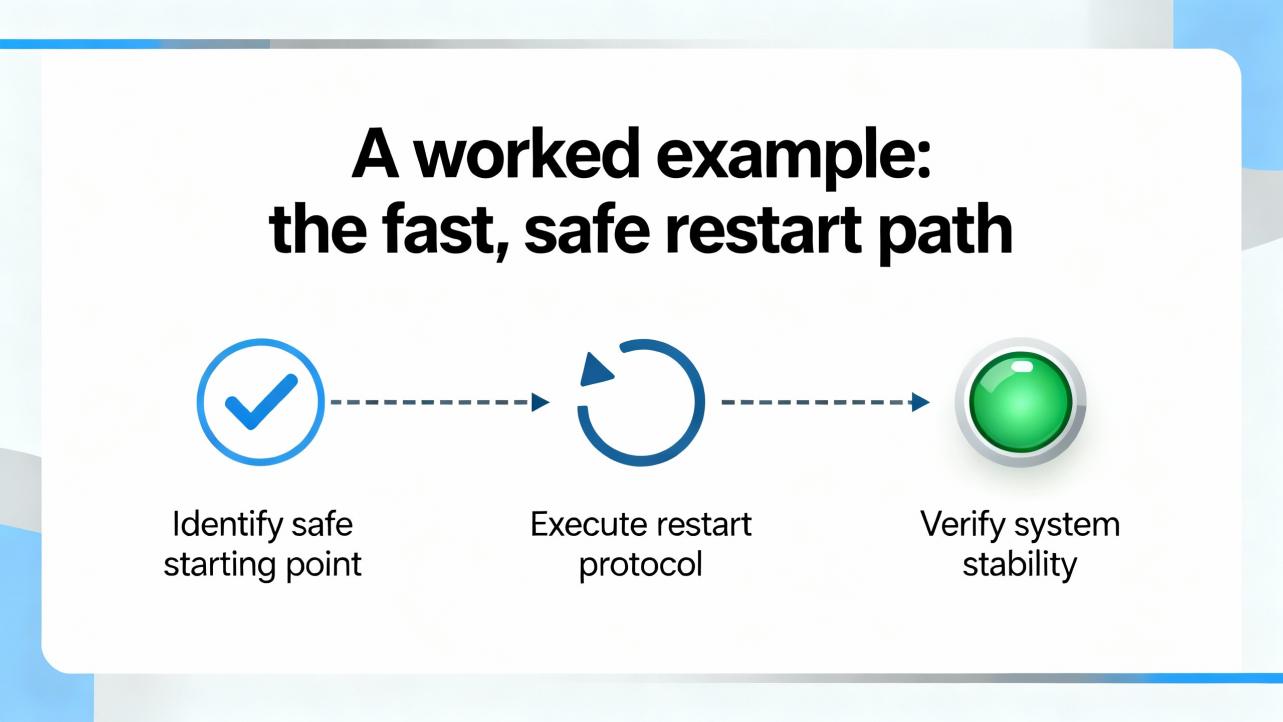
Imagine a cartoner stops and the HMI shows a controller fault. On arrival, the panel LEDs show the CPU in fault but power supplies are normal; the cabinet is hot to the touch because the afternoon sun is on the enclosure and the filter is layered with paper dust. The operator reports a short pause before the stop and a cascade of device faults. The right path is to open the door and ventilate, clean the filter, and let temperatures drop. With power and temperature stabilized, the I/O rack that showed a red module earlier is now healthy, but the CPU still shows a recoverable diagnostic. At this point, a warm restart is appropriate. The application resumes with retentive state intact, and the HMI sequence advances smoothly through its interlock checks. Finally, the operator runs a dry cycle and watches for nuisance alarms before returning to production. This sequence preserves evidence, addresses the cause, and uses the gentlest recovery action that clears the fault. Steps and hotfixes vary by model; this example follows common practice across PACŌĆæclass PLCs with medium confidence.
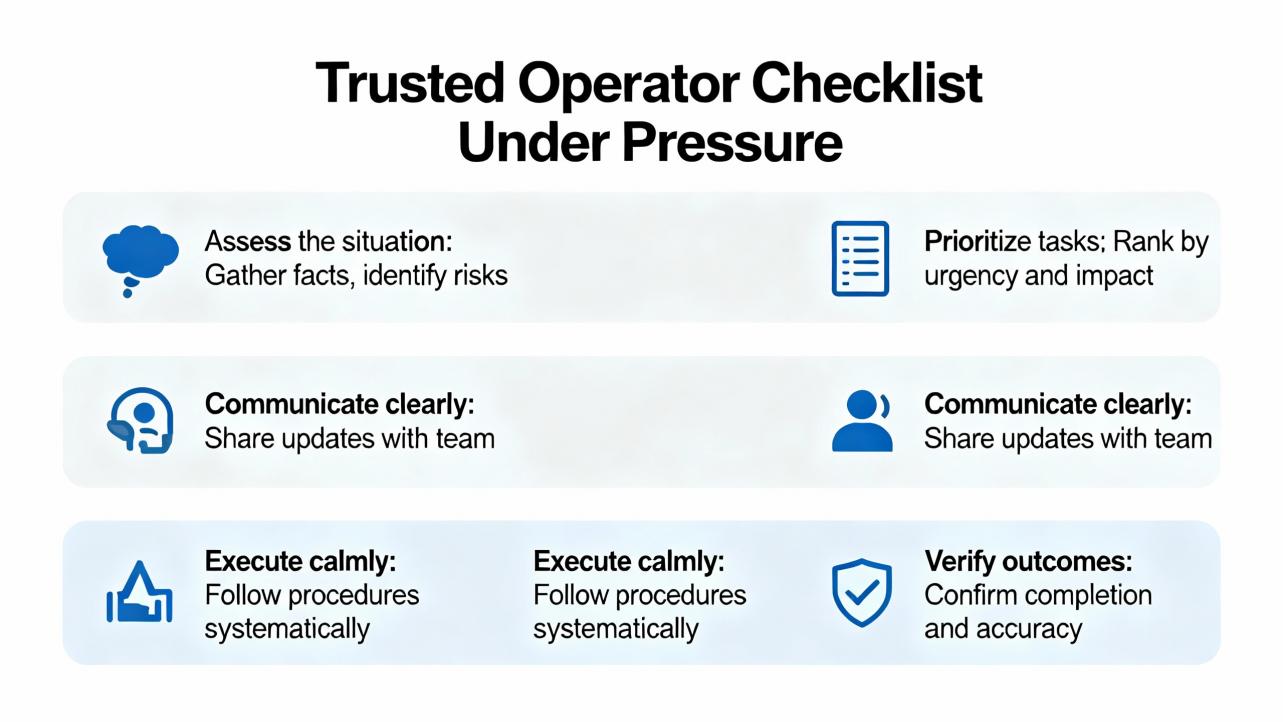
A controller fault is noisy, but recovery can be quiet and deliberate. Keep your routine simple: verify safe state and preserve data; stabilize power, heat, and network; choose the leastŌĆædisruptive restart that truly clears the diagnostic; and validate the process with a short test. The more you invest in backups, spares, and designedŌĆæin fault tolerance, the less you will need the rest of this article.
Controller faults are inevitable; unforced errors in recovery are not. The fastest safe recovery path starts with stabilizing the environment and collecting evidence, not clearing alarms. Warm restarts resolve many applicationŌĆælevel issues when power, temperature, and communications are healthy; cold restarts and power cycles should be reserved for corrupted state and deadlock. Operator performance improves dramatically when documentation is clear, backups are current, spares are on hand, and the system is built with redundancy and replication. These practices align with proven guidance on incident response, fault tolerance, and process fault diagnosis from respected sources in industrial and reliability engineering. If your current run book begins with ŌĆ£restart the PLC,ŌĆØ it is time to rewrite it.
Q: Should I powerŌĆæcycle a faulted PACŌĆæclass CPU right away? A: No. Power cycling is blunt and erases volatile logs that engineering needs for rootŌĆæcause analysis. Stabilize power, cooling, and the network, capture diagnostics, and prefer a warm restart if the fault is recoverable. Use a cold restart or power cycle only when state is clearly corrupted or hardware is deadlocked. This is consistent with faultŌĆætolerance fundamentals and industrial incident response guidance.
Q: When is a warm restart safer than a cold restart? A: Warm restarts preserve retentive data and minimize disruption, so they are appropriate when the environment is healthy and the diagnostic indicates a recoverable condition. Cold restarts reset all variables to initial values and should be chosen when state is unreliable or repeated watchdogs persist after environmental checks. This matches common PLC behavior across vendors with medium confidence; check your modelŌĆÖs manual.
Q: What should I document before I clear a fault? A: Record fault codes and text, time stamps, which devices were alarmed, and what changed just before the event. If possible, export alarm lists and event logs from the HMI or engineering station. This aligns with incident response good practice and enables engineers to isolate causes quickly rather than repeating the same recovery steps later.
Q: How many spares should we stock for the controller cabinet? A: Keep at least one spare CPU, one spare controller power supply, and the critical communications modules that would strand your line if they failed, plus a spare managed switch and the correct transceivers. Store program media or storage cards labeled with firmware and program versions. This mirrors industrial disasterŌĆærecovery advice and shrinks recovery time dramatically.
Q: How do I know networking is the real issue and not the PLC? A: If the CPU looks healthy and multiple HMIs or downstream devices drop at once, suspect the network. Check link lights and switch port status, and see whether other devices on the same switch respond. If redundancy exists, test the alternate path deliberately. FaultŌĆætolerant design places equal weight on redundant communications and controller health.
Q: What design upgrades reduce the chance IŌĆÖll face this again? A: Add redundant power and network paths where justified; improve panel cooling and power quality; automate controller backups and adopt version control for automation code; and standardize operator run books and engineering templates. These changes reflect faultŌĆætolerance and processŌĆæmonitoring research and pay back quickly in uptime and auditability.
This guidance blends operator field practice with published recommendations on fault detection and recovery, including surveys of FDIR and process monitoring (MDPI; Journal of Aerospace Information Systems), industrial incident response (CISA), disasterŌĆærecovery practices for ICS (Control.com), functional safety and lifecycle discipline (Pacific Blue Engineering), and faultŌĆætolerance principles (Fortinet; Splunk). ArchitectureŌĆælevel standardization and redundancy observations draw on DCS practice referenced by GE Vernova. DeviceŌĆæspecific steps and LED patterns vary by model; where generalizing across PACŌĆæclass PLCs, I have stated that explicitly and indicated medium confidence.


Copyright Notice © 2026 mooreautomated.com All rights reserved,Moore Automated is not an authorized distributor or representative of the manufacturers featured on this website. Brand names and trademarks featured are the property of their respective owners.


Leave Your Comment