


MP 3009X
Get A Quote
As an industrial automation engineer who has stood in front of tripped shutdown systems with production on the line, IŌĆÖve learned that the fastest path back to a safe, stable plant is a disciplined diagnostic approach grounded in how safety PLCs actually fail and recover. This guide distills practical, field-proven methods for HIMA safety PLC diagnostics, rooted in real incident patterns, standards-based principles, and what matters at the cabinet when every minute counts. You will find definitions, fault isolation tactics, recovery patterns, maintenance practices, and purchasing considerations tailored for HIMA platforms, while still applicable to safety systems more broadly.
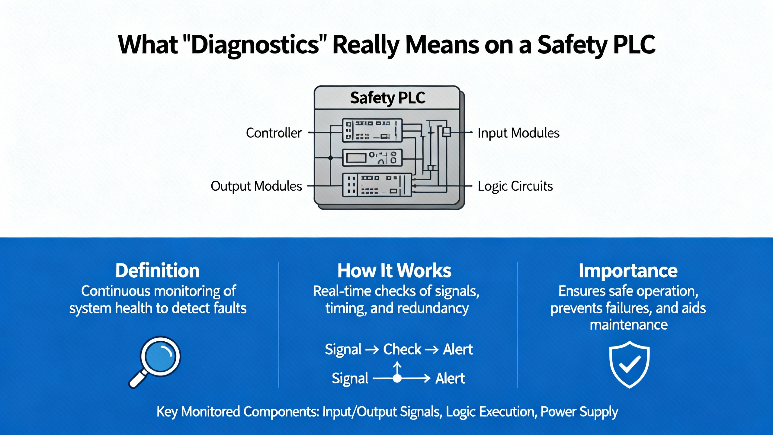
Safety PLC diagnostics exist to detect faults early, localize them precisely, and force a safe state when required. To talk about diagnostics clearly, use consistent terminology aligned with IEC language and HIMA publications. A fault is a defective state that might be latent or active. An error is the effect of a fault manifesting as a deviation from the required value or behavior. A failure is the observable loss of the required function at the system boundary. Hardware failures are typically random, while systematic failures can arise in hardware or software and stem from design, specification, or process weaknesses. In safety practice, failures are categorized by consequence and detectability. Safe failures do not compromise the safe state, even when undetected. Dangerous failures matter most; dangerous detectable failures can be driven to a safe state by a properly designed system, while dangerous undetectable failures are the critical residual risk that the safety lifecycle aims to minimize through diagnostics, proof tests, and robust processes. Safety performance metrics such as Probability of Failure on Demand (PFD) and Probability of dangerous Failure per Hour (PFH) quantify risk over time and should be tied to real diagnostic coverage and testing discipline.
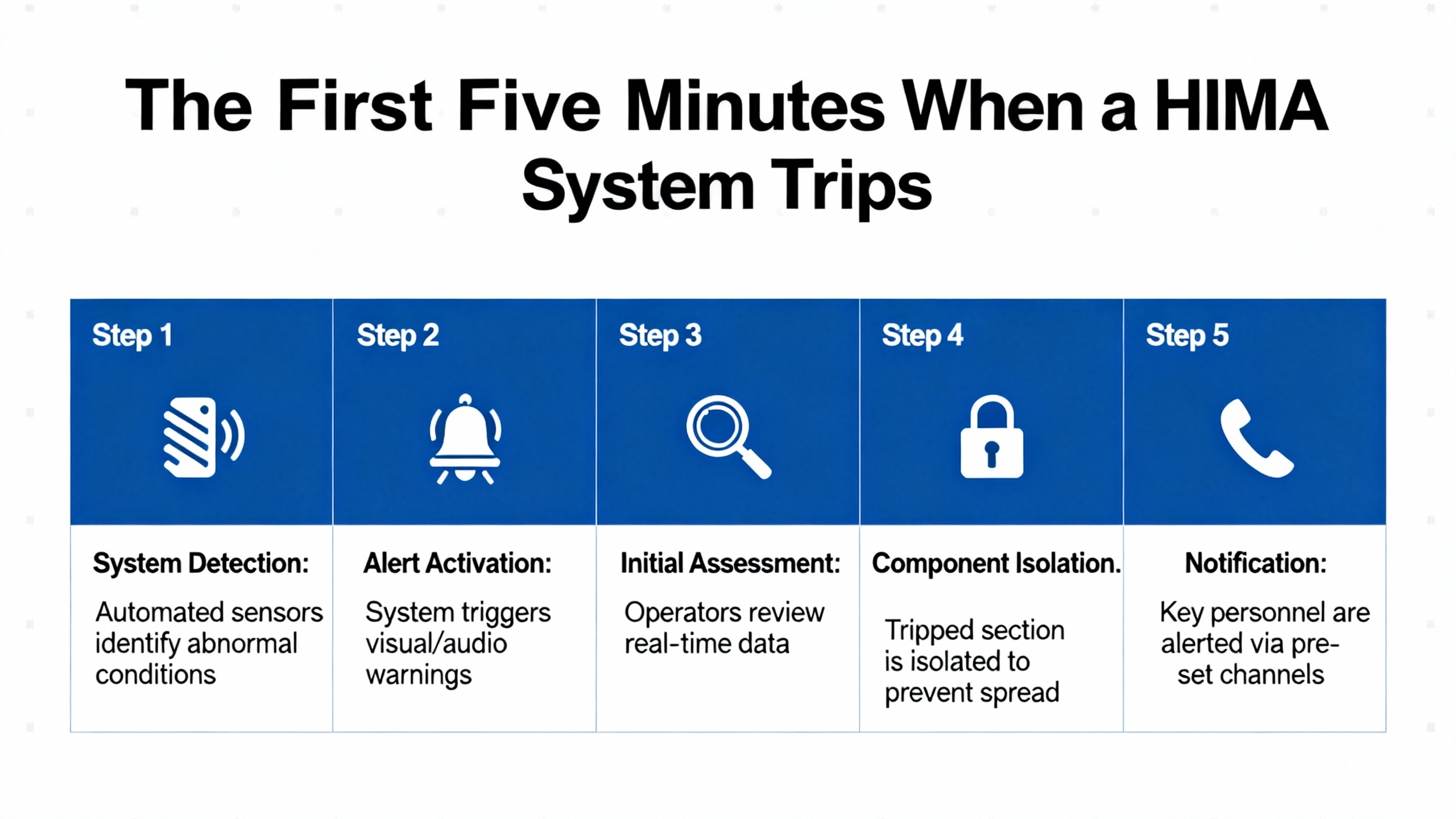
When a safety shutdown system trips, you need to separate symptoms from root causes immediately. A well-documented ammonia plant trip on June 23, 2010 at 4:41 PM shows what the first minutes often look like on a HIMA H51ŌĆæHS with redundancy. The operator sees multiple digital input fault codes across ranges like 1308ŌĆō1310 and 1407ŌĆō1410, a hardware watchdog indication, and an I/O bus fault flag emerging from a specific position. Acknowledge the errors and observe mode transitions. In the case above, RUN returned briefly, a redundant controller dropped to STOP, the other ran in MONO (single-controller mode), and then also stopped within minutes. Loading the last backup did not cure the issue, but loading only the primary CU worked. Replacing the second CPU module (F8620/11), reloading the application, and then proactively replacing the first module, restored redundancy and stability. That sequence points strongly to a faulty controller module or disturbed I/O backplane segment rather than bad application logic. The lesson is simple: widespread digital input bus errors, a triggered hardware watchdog, and brief recoveries often indicate a hardware or backplane path, not the program.
When a HIMA rack throws grouped codes, decode and map them to rack, slot, and channel. Use HIMA engineering tools to correlate 13xxŌĆō23xx input fault ranges and any special events like ŌĆ£187ŌĆØ to the exact hardware and bus position. Keep a printed or digital map of your rack and field connections that ties each code range to physical modules. If redundancy is in play, test and document switchover behavior after any corrective action. Confirm CPU firmware compatibility, and burn in replacement modules before putting them on the shelf as spares. These steps prevent chasing ghosts and minimize unnecessary module swaps during a time-critical shutdown.

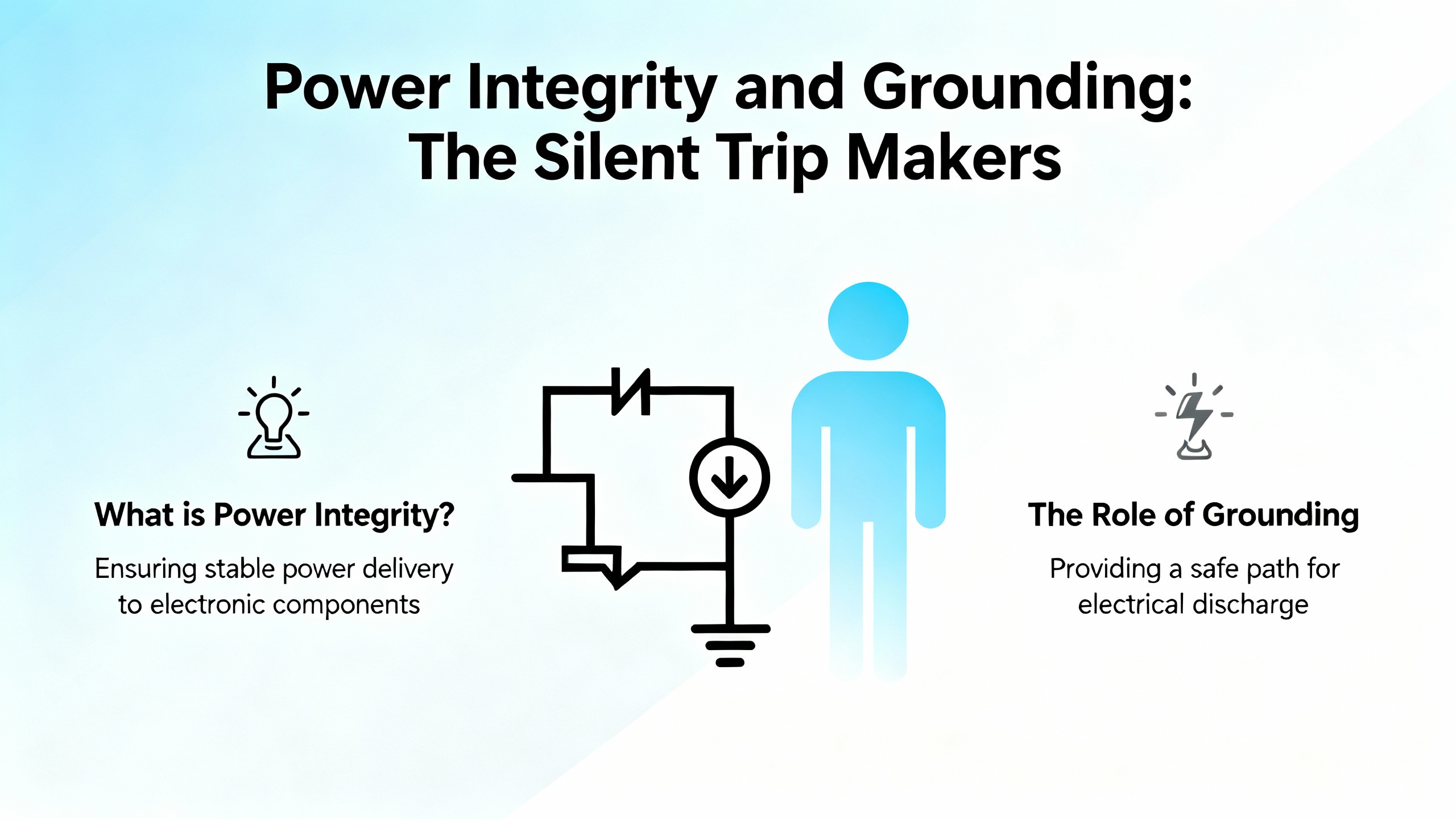
Power quality is the quiet saboteur of safety PLC stability. A dip on a 5 VDC rail can halt a CPU and disturb I/O logic; a marginal 24 VDC field supply can make a rack look haunted. Treat power like a root-cause suspect from the start. Verify the 5 VDC railŌĆÖs stability under load and no-load conditions and inspect for ripple. Confirm proper system grounding and a robust common ground reference. Ensure no floating voltages exist on the 5 VDC or 24 VDC rails relative to common ground. Use separate 24 VDC supplies for the CPU versus the I/O cards to avoid shared transients. If a power-supply card is adjustable, characterize its output under load and transient conditions and log behavior during suspected disturbance windows. Engineers who methodically clear power and grounding first simply fix safety PLCs faster.
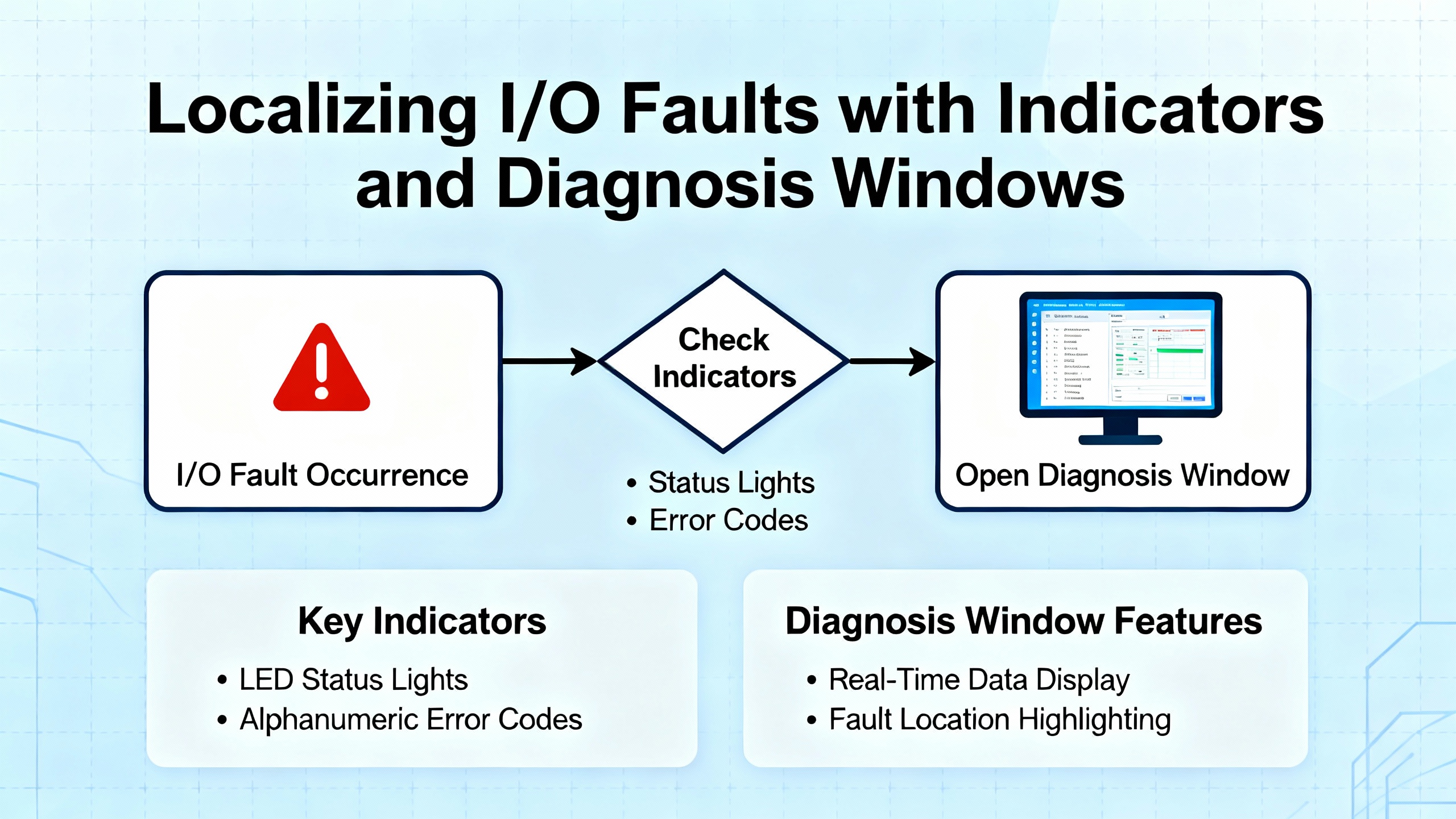
You do not always have to guess where faults live. Practical diagnosis techniques borrowed from general PLC tools are helpful. When connected online, a diagnosis window that shows all cards will indicate which modules are in distress, often in red, while a blinking red LED on a card indicates an active error. Power-related I/O faults such as loss of external 24 VDC typically clear automatically when the supply is restored. By contrast, sensor channels with no valid signal, such as a thermocouple channel configured but disconnected, often require restoring a valid signal and then clearing the error flag in the module status interface. Before attempting software resets, verify 24 V availability and input signal presence. Even outside HIMA tools, using LEDs and diagnosis views to localize problems is both fast and reliable.
A hardware watchdog forcing STOP is your friend, not your enemy. It tells you the system detected a condition that demanded a safe state. Acknowledge that reality and proceed methodically. Try bringing the application back to RUN via the supported engineering action, then observe whether the system re-enters STOP. If you can isolate a redundant controller that transitions to STOP recurrently while its peer can run in MONO, treat the failing CU as a primary suspect. Replace it with a known-good spare of the same type and firmware family, reload, and retest the redundancy switchover. Always document the alarm sequence and the exact state transitions. A clean paper trail is the most valuable asset when working with vendors and site leadership after the event.

Communication issues waste hours when teams jump straight into software. In established automation networks, the overwhelming majority of failures are physical. Damaged or loose cables, connectors, insufficient power, and failing comm cards cause most disruptions, with driver problems as the next most likely cause. If you are commissioning or adding devices, add one device at a time and verify communication before adding the next. Avoid default node numbers and IP addresses. When the quick checks fail, work layer by layer in the Open Systems Interconnect model, starting with the physical layer and moving upward. This discipline resolves most communication anomalies without prolonged downtime.
Treat PLC program management as a reliability function. Configure nonŌĆævolatile storage to auto-load the correct application on memory errors. Every time you go online with a controller, save a snapshot and tag it with ŌĆ£currentŌĆØ or ŌĆ£faultedŌĆØ so you can return the system to the exact state you observed. For intermittent problems, add a temporary rung that latches a bit when suspected conditions align, then remove it once you confirm the root cause. If you encounter a math overflow signature, such as a value of 37,767 in memory, consider it a programming defect and address the logic accordingly. Lastly, keep the design as simple as the process allows. Complexity multiplies failure probability and hides the path to the root cause.
HART overlays a digital signal on the 4ŌĆō20 mA loop and is immensely useful in diagnostics and asset management. In SIS design and operations, the 4ŌĆō20 mA analog path remains the safetyŌĆærelevant signal. Treat HART as advisory; do not use HART diagnostic data to execute trips or safetyŌĆæcritical logic. Keep HART write operations locked out during normal operation and segregate maintenance or asset networks from safety networks. Apply NAMUR NE 107 status categories so the maintenance team interprets device health consistently, and use NE 43 current conventions to minimize spurious trips. If you take credit for diagnostic coverage in SIL calculations, anchor the assumptions in your lifecycle documents and align proof test intervals with real diagnostic performance. HART is polled and low bandwidth, which makes it unsuitable for timeŌĆæcritical interlocks, but it is excellent for quicker commissioning, better proof test coverage, and faster fault localization.
| HART Practice in SIS | Purpose in Operations | Boundary You Should Not Cross |
|---|---|---|
| Keep 4ŌĆō20 mA as the safety path | Preserve deterministic, safetyŌĆærelevant input | Do not trip solely on HART diagnostics |
| Treat HART as readŌĆæonly in run | Enable remote health checks and commissioning | Do not allow writes in operation |
| Segment asset access | Reduce cyber exposure and shared failure modes | Do not commingle safety and asset networks |
| Use NE 107 and NE 43 | Standardize health interpretation and fault currents | Do not improvise meanings for device flags |
Source: HIMA white paper content as published via Provincial Controls.
Diagnostic speed comes from choosing the most probable domain first, not from swapping parts. A sound rule is that physical and mechanical issues dominate, followed by electroŌĆæmechanical, then realŌĆæworld I/O issues, then finally PLC modules. In networks that once worked and now do not, physical causes typically account for the overwhelming majority of failures. This is why confirming 24 V field power, checking connectors, and verifying signal presence resolves many supposed ŌĆ£logicŌĆØ problems in minutes. When you do cross into the PLC hardware domain, trend logs and precise fault code mapping will keep your actions surgical.
| Symptom Seen by Crew | Likely Root Domain | First OnŌĆæSite Action | Source Insight |
|---|---|---|---|
| Watchdog STOP with many DI faults and brief RUNs | Controller module or I/O backplane disturbance | Acknowledge, observe mode transitions, map DI faults to positions, swap suspect CU with tested spare, retest redundancy | Automation & Control Engineering Forum, Ammonia Plant case |
| CPU halt with I/O disturbances during normal operation | 5 V dip, ripple, or grounding issues | Scope the 5 V rail, check for ripple, separate 24 V supplies CPU vs I/O, fix grounding and floating voltages | Automation & Control Engineering Forum power guidance |
| Module LED blinking red, diagnosis shows card in red | Field 24 V loss or missing sensor signal | Restore 24 V; if channel alarm persists, provide valid signal then clear module error in status | Maple Systems diagnostics tutorial |
| Communications intermittent after changes | Physical connectors or driver state | Reseat cables, replace suspect patch, reinstall driver, reboot engineering station if needed | PLCŌĆæTraining.org best practices |
Regardless of the engineering tool you use, commit to a repeatable pattern for fault decoding. Go online and export the event and error log. In known HIMA sequences, a hardware watchdog masked alongside grouped DI faults with an earliest fault at a specific bus position points you to a module or backplane segment. Note special event IDs such as ŌĆ£187ŌĆØ and consult vendor documentation. Use the toolŌĆÖs quick RUN action, and watch whether the system returns to STOP. If the redundant pair toggles between MONO and STOP upon loading the joint application, isolate each CU independently with the latest backup and see which runs reliably. When mapping codes to hardware, confirm the exact rack, slot, and channel to avoid intrusive checks on the wrong segment. Finally, leave a succinct record of what you saw before, during, and after the failure so the next team can start where you finished.

Every action around safety PLCs is a safety action. Follow lockout/tagout per 29 CFR 1910.147 before altering wiring, removing modules, or forcing I/O. Save copies of the program the moment you go online and tag them carefully. Keep all personnel who troubleshoot trained in PLC fundamentals and the reliability practices in this guide. Diagnostics are only as good as the process around them. Better discipline reduces systematic faults and, just as importantly, avoids introducing new ones during a highŌĆæstress recovery.
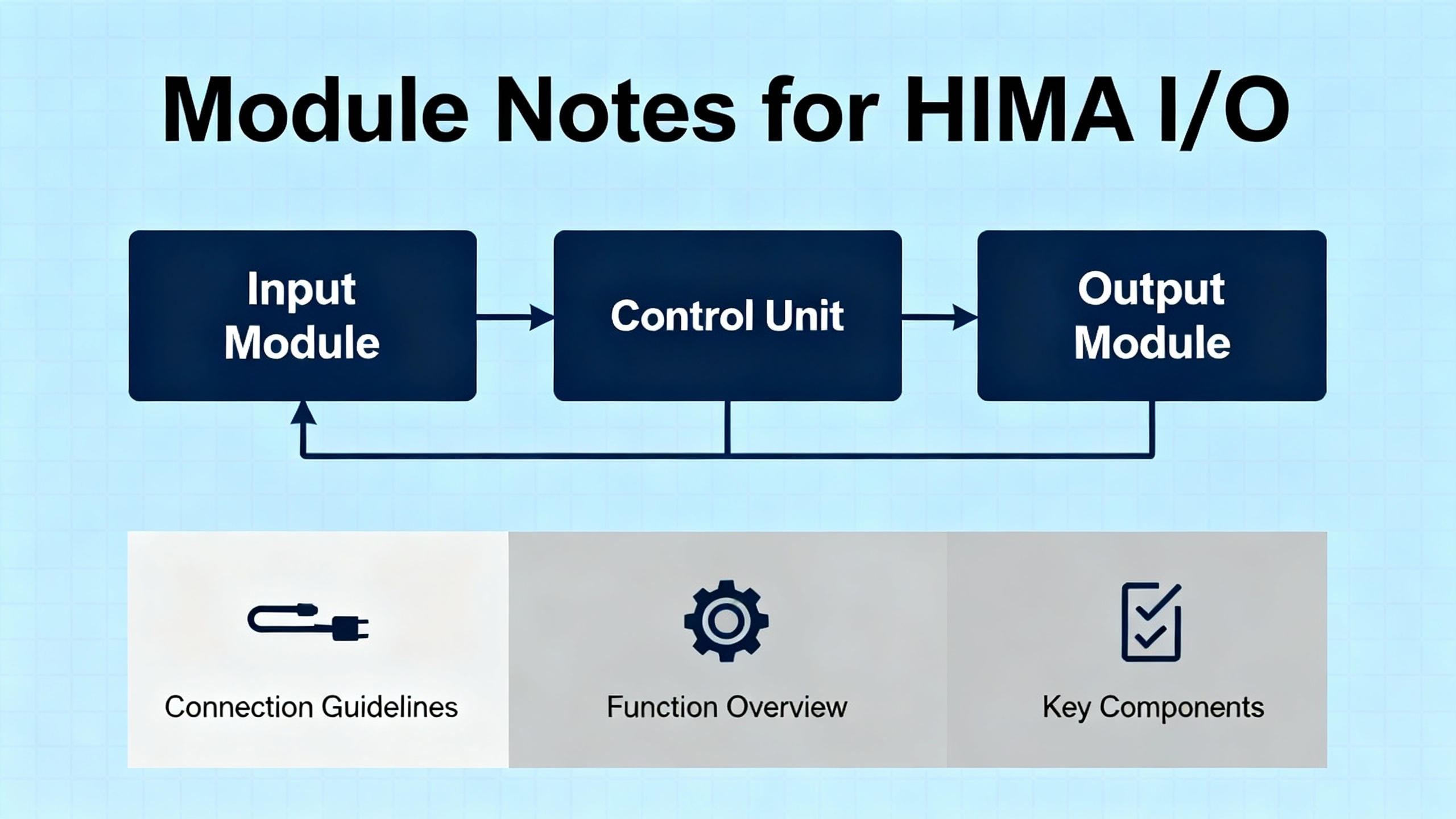
HIMA I/O families pair rugged design with redundancy options and builtŌĆæin diagnostics. Output modules such as the F3113A include redundant power paths with onŌĆæboard diagnostics to maintain outputs even if one supply fails. Input modules such as the F3236 provide multiple channels with isolation and fault detection to improve signal integrity and make channelŌĆælevel fault localization straightforward. Accessory parts like the Z7108 LED cable plug offer immediate visual cues about link or channel status, which materially shortens troubleshooting time on crowded backplanes. Choose modules that are certified to IEC 61508 where the application requires it and configure redundancy and diagnostics deliberately rather than as afterthoughts.
When your safety PLC trips and you are back online with the cabinet in front of you, a proven recovery pattern helps. Start with power integrity checks on the 5 V internal rail and 24 V field supplies. Confirm system grounding, remove floating voltages, and separate supplies if they are shared. Go online, export logs, and decode grouped errors; map DI and DO codes to rack positions. Bring the application to RUN; if STOP recurs, test redundant controllers individually. Replace suspect CUs with knownŌĆægood spares of a compatible firmware family, reload the application, and verify MONO operation followed by redundancy switchover tests. If I/O modules display persistent alarms, address sensor power, signals, and module status resets. Document the sequence and the corrective actions taken, then schedule a followŌĆæup on firmware alignment, backplane inspections, and environmental checks once production is stable.

Buying and maintaining with diagnostics in mind prevents long, painful nights later. Favor IEC 61508ŌĆæcertified modules where required so that diagnostic claims and failure behaviors are documented and credible. Validate that controller and I/O firmware are compatible and that the shop has the tools and licenses to load and analyze logs. Stock spare CPU modules of the same type and firmware family and burn them in under load before they go on the shelf. Verify redundancy support in both CPUs and communication paths and test switchover under supervision during planned windows. Match environmental ratings to your plantŌĆÖs real conditions, including dust, moisture, and vibration, rather than brochure assumptions. If your instruments are HART capable, plan asset access that respects SIS independence, including segmentation and write locks. For rack visibility, include LED accessories that turn cable and link status into quick visual checks. Above all, keep backups of applications and configuration, including a verified autoŌĆæload path on memory errors, so a knownŌĆægood image is always one action away.
| Consideration | Why It Matters | How to Verify |
|---|---|---|
| IEC 61508 certification | Aligns diagnostics and failure behavior with functional safety | Check module certificates and safety manuals |
| Firmware compatibility | Prevents subtle redundancy and I/O issues | Confirm versions across CUs and I/O; align before goŌĆælive |
| Redundancy features | Ensures safe switchover without trips | Run supervised switchover tests after maintenance |
| Environmental rating | Avoids latent faults from dust, moisture, vibration | Match specs to real plant conditions and cabinet placement |
| HART and asset access | Gains diagnostics without compromising SIS | Enforce readŌĆæonly in run, segment networks, audit changes |
| Spare strategy | Shortens recovery and reduces risk during replacements | Burn in spares, label by firmware, store with test records |
| Visibility accessories | Speeds physical checks during incidents | Add LED plugs and maintain lamp test procedures |

Log everything atypical before, during, and after a failure. Small observations, such as a module that briefly blinks red when a compressor starts, often crack the case later. Keep a codeŌĆætoŌĆæhardware map for every rack. Archive CPU and I/O errorŌĆæcode references and keep a local copy accessible without network dependency. Save program snapshots the moment you connect and again at each decisive step in recovery, including the image that stabilized the plant. This discipline also makes postŌĆæevent analysis with the vendor faster and more productive.
What does it mean if the system returns to RUN but then stops again in a minute or two? That pattern, when combined with broad DI faults and a hardware watchdog, often signals a failing controller module or disturbed I/O backplane. Load one CU at a time, see which runs in MONO, and replace the suspect hardware. Verify power quality in parallel.
Do I ever clear module errors without fixing field conditions first? Avoid clearing errors until you restore the underlying condition, such as 24 V to the field or a valid sensor signal. Some modules require a manual reset after a valid signal is present, but many powerŌĆærelated errors clear automatically once power returns.
Can I trust HART for trips? No. Keep the 4ŌĆō20 mA analog path as the safety input. Use HART for diagnostics, commissioning, and maintenance. Lock out writes during normal operation and segment asset access from the safety network.
Is there a quick way to catch intermittent faults? Yes. Add a temporary trap in logic to latch a bit when the suspected conditions coincide, then remove that rung once you confirm the event. Back up the program with a ŌĆ£faultedŌĆØ suffix so you can study the exact state later.
If you are standing in front of a tripped HIMA rack, breathe, start with power and grounding, decode with purpose, and move from the most probable domain to the least. The plant needs you focused, disciplined, and methodical. That approach is what turns a scary red screen into a stable green one without compromising safety.
| Publisher | Reference |
|---|---|
| Automation & Control Engineering Forum | HIMA PLC power and grounding troubleshooting discussion with guidance on 5 V dips, separate 24 V supplies, grounding, and ripple checks (advice attributed to Rehan Asif) |
| Automation & Control Engineering Forum | HIMA H51ŌĆæHS ammonia plant incident detailing DI fault sequences, hardware watchdog behavior, ELOP recovery attempts, F8620/11 module replacement, and redundancy restoration |
| Maple Systems | PLC Diagnostics tutorial describing diagnosis window usage, module LED cues, powerŌĆæloss fault clearing, and manual error resets on certain modules |
| PLCŌĆæTraining.org | PLC Troubleshooting Best Practices covering safety and reliability habits, failureŌĆædomain probabilities, 3Ps mindset, communication fault likelihood, OSI layering, EEPROM autoŌĆæload, and program management tips |
| HIMA | Dependable Systems article on errors, faults, and failures including definitions, failure propagation, and recommendations on diagnostics coverage and systematic fault reduction |
| HIMA via Provincial Controls | HART in Safety Instrumented Systems white paper clarifying that HART is for diagnostics and asset management, not safety trips, with guidance on NE 107, NE 43, network segmentation, and cybersecurity |
| PLC Leader | Overview of HIMA I/O module design attributes and examples including F3113A, F3236, and Z7108 with redundancy, isolation, and diagnostic benefits |


Copyright Notice © 2026 mooreautomated.com All rights reserved,Moore Automated is not an authorized distributor or representative of the manufacturers featured on this website. Brand names and trademarks featured are the property of their respective owners.


Leave Your Comment