


MP 3009X
Get A Quote
When I walk into a plant to commission or troubleshoot a control system, the most valuable document in the cabinet is almost never the glossy product brochure. It is the wiring diagram that shows exactly how the field devices land on each terminal of the I/O modules, including modules labeled something like KJ3222X1-BA1. If you can read that wiring diagram with confidence, you can wire, diagnose, and modify the system without guesswork or unnecessary downtime.
This guide approaches the KJ3222X1-BA1 as the tag for a PLC or DCS I/O module in your cabinet. The goal is not to replicate the manufacturerŌĆÖs manual, but to show how to use the wiring diagram to connect it correctly, verify those connections, and avoid the failure patterns that show up repeatedly in real plants.
Many engineers receive a bundle of drawings and treat them all the same. That is how mistakes creep in. Training resources such as the Testguy Electrical Drawings overview and SkillCatŌĆÖs blueprint guides stress that each drawing type has a different purpose.
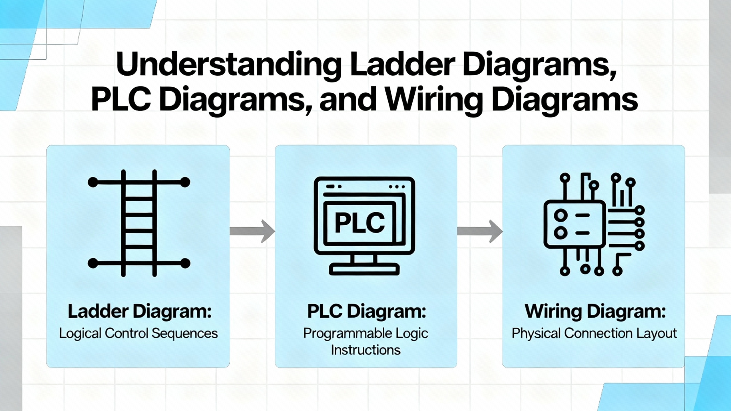
A wiring diagram focuses on physical connection and identification. It shows the module, its terminals, terminal blocks, plugs, cable cores, wire numbers, sometimes even color codes. This is often the drawing you use when you physically land the KJ3222X1-BA1 terminals to field devices and marshalling strips in a cabinet.
A schematic, as described by JLCPCB and SparkFunŌĆÖs tutorials, uses standardized symbols and nets to show how the circuit functions logically. It is much less concerned with the physical path of the conductors. Relays, fuses, sensors, and the I/O module appear as logical symbols with named nets such as 24V, DI_01, or AO_04, and nodes indicating junctions. You use this when you want to understand how the system behaves electrically and logically.
Single-line diagrams, highlighted in the Testguy overview, present a birdŌĆÖs-eye view of power distribution. They show feeders, transformers, breakers, and major loads as single lines with ratings and voltages. These rarely show the individual terminals of a KJ3222X1-BA1, but they tell you what power system your control panel lives in and how it should be switched.
When you talk about ŌĆ£the KJ3222X1-BA1 wiring diagram,ŌĆØ you are usually referring to the sheet that combines physical terminals, wire identifiers, and enough symbolic information to let an installer and troubleshooter work safely and accurately.
ControlByteŌĆÖs guidance on reading electrical wiring diagrams calls this a core professional skill rather than a nice-to-have. That is consistent with what I see in the field. If you only understand ladder logic or function block diagrams on the PLC side, but cannot interpret the wiring diagram, you will be blind to a large class of real-world faults: swapped cores, mis-landed commons, missing shields, and devices powered from the wrong voltage level.
Wiring diagrams for industrial control can run from a handful of pages for a small machine to well over 200 pages for a large plant panel, as UpmationŌĆÖs material notes. In those bigger systems, module tags such as KJ3222X1-BA1 may appear across many pages: power distribution, I/O channel details, interposing relays, and marshalling. The only way to stay in control is to develop a systematic reading and connection method.
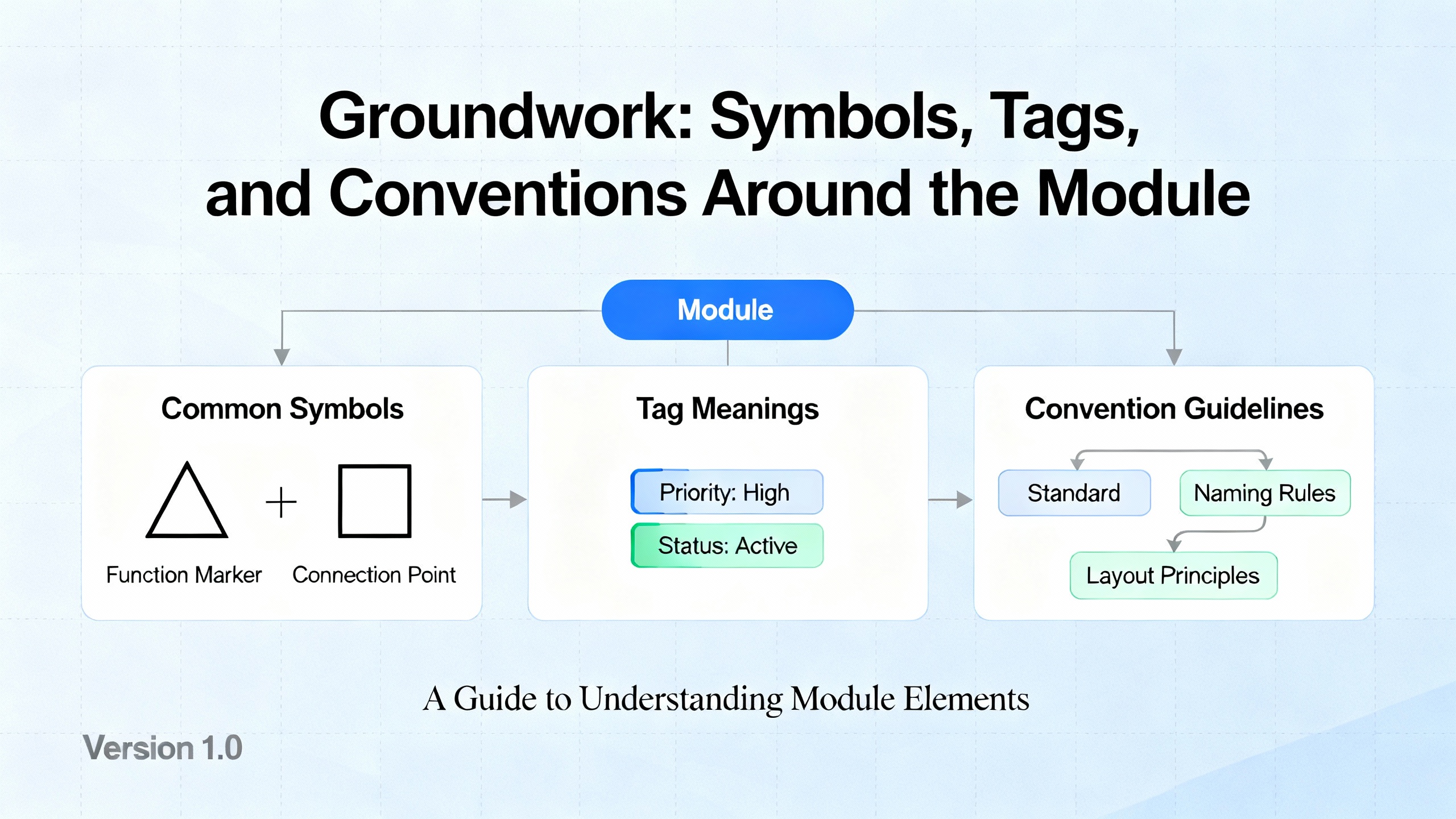
Resources from SparkFun, JLCPCB, and UTIŌĆÖs wiring symbol guide all say the same thing in different words: symbols are your language. Around a PLC or DCS I/O module, expect to see at least the following symbol families.
You will see power and voltage nodes that represent the different supply rails feeding the module and the field circuit. These may be labeled 24V, 120VAC, or similar, with ground or common symbols for returns. They allow the designer to avoid drawing every power conductor.
Protective devices such as fuses and breakers are usually shown with distinct symbols and possibly ratings in text. JLCPCB emphasizes that these belong near the nets they protect and should be clearly labeled.
Switches, relays, and contactors appear around the module whenever discrete outputs drive power circuits or interposing relays. Ladder-diagram conventions, as described by Zuken and Eng-Tips discussions, place power rails as vertical lines and contacts and coils as horizontal rungs, so the KJ3222X1-BA1 output channel may appear as a small block or contact feeding the coil symbol of a relay.
Connectors and terminal blocks are central to wiring diagrams. SparkFunŌĆÖs connector examples and SkillCatŌĆÖs blueprint guide both stress that connectors must show pin numbering and clear reference designators so you can map each wire from module to field.
Professional schematic guidance from sources such as Electrical Technology, JLCPCB, and the ControlByte article stresses consistent designators. Every component on the wiring diagram should have a unique tag so that when you see KJ3222X1-BA1 on one sheet and again on another, you know it is the same physical module.
Industrial documentation often uses structured tags influenced by IEC 81346-1, as ControlByte notes. A simple practical interpretation is that tags encode function, location, and product. For example, the panel might have a location tag, the module a product tag such as -KJ3222X1-BA1, and the channel an additional suffix such as :CH01. Even if your plant does not follow IEC strictly, a consistent tag scheme makes it possible to trace a wire from the I/O card channel back through terminal blocks to the field device without guesswork.
Eng-Tips contributors emphasize the importance of line and wire numbers for ladder diagrams and wiring diagrams. Lines are often numbered in steps of ten or one hundred, while individual wires receive numbers derived from those lines. This is incredibly useful around a module such as KJ3222X1-BA1 because you can cross-reference a wire number printed on the conductor insulation back to a specific rung and terminal in the drawing.
Training content from SkillCat, UTI, and Facebook-based educational groups all recommend the same first step: read the title block and legend. Before you chase any wire, confirm the drawing set, revision, panel designation, and applicable voltage levels.
The legend explains the symbols, line types, and often color codes used. Since standards and CAD libraries differ between companies, assuming that you ŌĆ£recognizeŌĆØ a symbol can be dangerous. If the legend specifies that a dashed line represents a shield drain or a removable jumper, you must know that before planning your wiring for the KJ3222X1-BA1.
Next, locate every occurrence of the KJ3222X1-BA1 tag. In a small system, the module might appear on a single sheet with its full terminal list. In larger panel drawings, I/O modules are sometimes summarized on one sheet and then broken out by function on others.
Look for:
Terminals or pins labeled with numbers or codes, for example 1, 2, 3, or functional names such as CH1+, CH1ŌĆō.
Associated power or common terminals, which might be shared for several channels.
Cross-reference notes that point to related sheets, such as ŌĆ£see sheet 15, line 120ŌĆØ or references to terminal blocks like TB1-17.
Following recommendations from the JLCPCB and SparkFun schematic guides, well-drawn diagrams will keep related pins grouped functionally rather than strictly by physical order, so do not assume that the drawingŌĆÖs left-to-right order exactly matches the plastic header order. Always cross-check with the manufacturerŌĆÖs terminal diagram when you are in doubt.
ControlByteŌĆÖs article encourages technicians to practice tracing circuits end to end, and that habit is critical for I/O wiring. For each KJ3222X1-BA1 channel you intend to use, mentally walk the entire path from the module terminal to the field device and back.
For a discrete input, start at the input terminal on the module, follow the line to any terminal block, then onward to the field cable and sensor or switch. Identify where the return path or common is shown and confirm whether it is shared between channels. Check whether any series devices such as fuses, selector switches, or safety interlocks exist along this line.
For an output channel, the same tracing applies, but you must pay particular attention to whether the module is sourcing or sinking, and whether the wiring diagram shows an interposing relay or contactor. ZukenŌĆÖs guidance on ladder diagrams suggests keeping inputs conceptually on one side and outputs on the other; apply that mentally even when the drawing mixes elements on one page.
UTIŌĆÖs symbol guide stresses the importance of connection dots and crossing lines. Whenever the line from a module terminal crosses another conductor, look for the node dot that indicates a true connection. Absence of that dot implies that the wires cross visually but are not electrically joined. Misreading these crossings is a classic way to miswire or misdiagnose an I/O module.
ControlByteŌĆÖs notes highlight potential lines and labels such as +12V, +24V, and GND. With a module like KJ3222X1-BA1, control circuits may share a 24 VDC rail, while the plant also has 120 VAC or higher power nearby on the same drawing. Before you approve any wiring, confirm that:
Each channel is shown tied to the correct voltage source for its field device.
Commons and returns are consistent with the moduleŌĆÖs requirements.
Any isolation barriers or separate supply domains are clearly respected; wiring across those boundaries incorrectly can damage both module and field device.
TestguyŌĆÖs overview of schematics recommends that all contacts and switches appear in their de-energized state. That means you need to think about how the circuit will behave when energized rather than assuming the drawn switch positions are ŌĆ£normal runningŌĆØ positions. When working with safety or emergency circuits, this matters a great deal for how you wire normally closed versus normally open contacts to the module.
On larger jobs, I rarely wire directly from the diagram. Instead, I or the design team build a wire list that translates the diagram into a structured table. An experienced wire design engineer on the EEVblog forum described how professional tools build this as a ŌĆ£netlistŌĆØ inside a database, but also pointed out that a careful spreadsheet can achieve the same result for modest systems.
A wire list helps you:
Plan terminal usage on the KJ3222X1-BA1.
Coordinate with panel builders who need a clear table rather than flipping through dozens of pages.
Support future maintenance, because each wire number maps to explicit ŌĆ£fromŌĆØ and ŌĆ£toŌĆØ points.
Based on that EEVblog discussion and common industry practice, an effective wire list uses columns similar to the ones in the table below.
| Column | What it represents | Example entry |
|---|---|---|
| FROM_REF_DES | Originating device or terminal block tag | KJ3222X1-BA1 |
| FROM_PIN | Originating terminal or pin number | 01 |
| WIRE_GAUGE | Conductor size specification | 18 AWG |
| SIGNAL_TYPE | Functional type of signal | DI (limit switch) |
| TO_REF_DES | Destination device or terminal block tag | LT-101 or TB1 |
| TO_PIN | Destination terminal or pin number | 3 |
| WIRE_NUMBER | Unique wire identifier on prints and in the panel | 1103 |
| COMMENTS | Any notes (shield, color, part of cable, routing constraints) | In multi-core cable CBL-27, shield tied at panel |
EEVblogŌĆÖs engineer recommended building this table in both directions, so you can trace from the module out to the field and from the field back to the module. For an I/O module like KJ3222X1-BA1, that means you might start by listing every channel you plan to use, then add field devices and terminal blocks until every module terminal and every field connection appears at least once in the table.
SkillCatŌĆÖs training material on electrical drawings suggests keeping this data aligned with your panel schedule and as-built drawings. That way, whenever a technician sees wire number 1103 on the conductor in the cabinet, they can immediately locate the corresponding row in the wire list and the exact terminals on the KJ3222X1-BA1 and the field device.
UpmationŌĆÖs series on wiring diagrams emphasizes that reading a PLC wiring diagram is a natural extension of reading simple control circuits. At some point, your wiring diagram will intersect with the PLC or DCS logic for the KJ3222X1-BA1. Understanding both views is vital.
ZukenŌĆÖs discussion of ladder diagrams explains that each rung typically represents a specific control function, with coils and contacts laid out so that you can visually follow the logic. Eng-Tips contributors recommend arranging PLC ladder prints so that inputs appear on one side, outputs on the other, with the physical panel wiring on the same drawing and the PLC or control module as a block.
In practice, here is how you combine these views. Use the wiring diagram to confirm that the physical sensor or actuator is correctly wired to the right channel of KJ3222X1-BA1. Then look at the PLC or DCS logic where that channel tag appears in ladder or function block form. If the logic is correct but the field device is not behaving, the fault lies in wiring, field device, or module. If the wiring checks out but the logic does not match the intended behavior, you know the problem is on the programming side.
This separation of concerns, emphasized in multiple educational sources, is what allows you to troubleshoot efficiently without guessing.
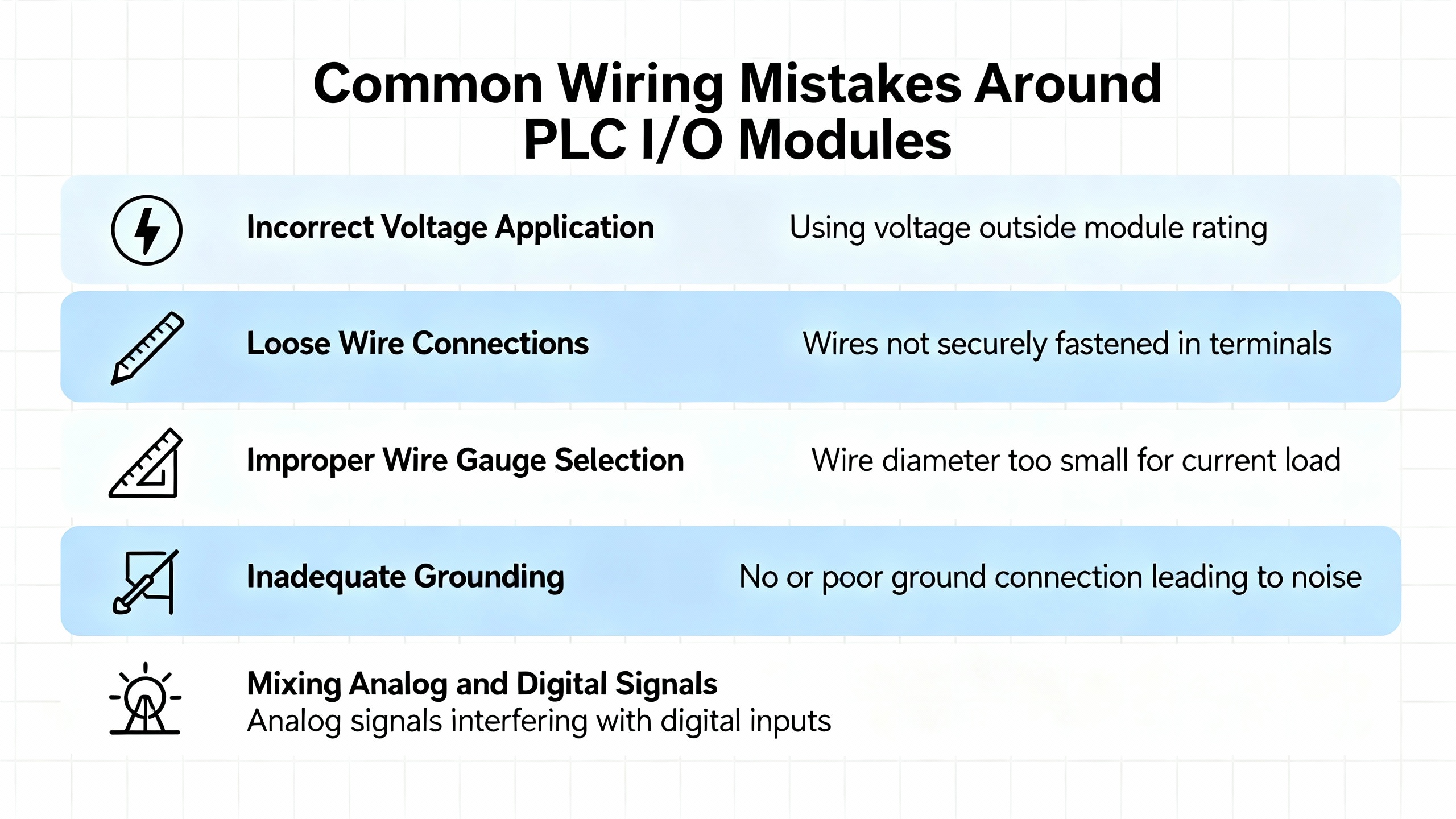
When I am called onto a site where an I/O module is ŌĆ£deadŌĆØ or ŌĆ£unreliable,ŌĆØ the root cause is often not the card itself but the way it was wired according to, or sometimes in spite of, the wiring diagram.
One common issue is ignoring terminal numbers printed on both the module and the diagram. SkillCat and UTI both highlight the importance of matching wire labels and terminal IDs to the print. Swapping two adjacent cores on a dense module header produces intermittent, confusing symptoms, especially when the PLC program still expects the original channel mapping.
Another frequent mistake is misreading crossing lines on the diagram and assuming they are connected. UTIŌĆÖs explanation of node dots is very clear: a dot means connected, a mere crossing generally does not. In multi-page plant diagrams, hurried engineers sometimes extend this confusion to off-page connectors and net labels, causing them to tie commons or shields where they should not.
Eng-Tips practitioners point out that clarity of annotation is often more important than strict drawing style. Poor or missing wire numbers, unlabeled terminal strips, and contact references that do not show which coil they belong to will all slow down troubleshooting and encourage ad-hoc ŌĆ£fixesŌĆØ at the KJ3222X1-BA1 terminals. Those fixes then go undocumented, leading to long-term reliability problems.
Finally, TestguyŌĆÖs emphasis on as-built drawings is crucial. Many cabinets are wired correctly according to the original plan, then modified during commissioning without any update to the documentation. Months later, a technician references the original diagram while the physical panel reflects multiple undocumented changes. The result is misdiagnosis, downtime, and occasionally a damaged module. If you change wiring on or around the KJ3222X1-BA1, update the diagram or at least redline it immediately.
Before you energize anything, treat the wiring diagram as a checklist. JLCPCBŌĆÖs schematic-troubleshooting advice suggests checking connections section by section. For the KJ3222X1-BA1, that means confirming:
The correct supply voltage is present at the moduleŌĆÖs power terminals, with polarity according to the manufacturerŌĆÖs requirements.
Each channelŌĆÖs field wiring matches the wire list and the wiring diagram, including terminal numbers and any series devices.
Commons and returns are wired as shown, without accidental ties between isolated groups.
You can perform continuity checks with a multimeter between the module terminals and the field device terminals. SkillCatŌĆÖs training notes encourage using the drawings as a map for these tests rather than probing blindly.
Once basic checks are complete, you can perform live tests. For discrete inputs, use the wiring diagram to identify how the field device should drive the channel. Operate the device and confirm that the correct diagnostic indicator on the KJ3222X1-BA1 (if present) and the corresponding PLC input bit both respond as expected.
For outputs, verify that energizing the channel in the logic causes the correct physical device, and only that device, to respond. Eng-Tips accounts of well-annotated PLC ladders demonstrate that this functional correlation, backed by good prints, made it possible to diagnose issues nearly entirely from the desk when needed.
Throughout this process, remember the safety emphasis from Testguy and SkillCat: never rely on the wiring diagram alone to assume that a conductor is de-energized. Treat the diagram as intent and the meter as truth, and follow your facilityŌĆÖs lockout and tagging procedures.
When final wiring and testing are complete, you must synchronize the documentation with reality. TestguyŌĆÖs description of as-built drawings stresses that they should reflect all deviations from original design, with clear approval records. This includes any changes you made to terminals, wire numbers, or channel allocations on the KJ3222X1-BA1 during commissioning.
SkillCat recommends keeping both digital and paper copies of updated drawings easily accessible. In practice, I encourage teams to maintain a controlled PDF set in a shared drive or document system and a printed copy in the panel, with a clear mechanism for replacing outdated versions. That way, the next engineer who opens the cabinet is working from the same truth you just verified.
Different diagram types complement each other around a module like KJ3222X1-BA1. ZukenŌĆÖs discussion of schematic, pictorial, and ladder diagrams, along with guidance from SmartDraw and Uplan on wiring diagrams, can be summarized as shown in the table below.
| Diagram type | Shows best | How it helps with KJ3222X1-BA1 |
|---|---|---|
| Wiring | Physical connections, terminals, wire and cable details | Guides actual landing of wires and terminal assignments |
| Schematic | Logical function and interaction of components | Explains how the module fits into the control strategy |
| Ladder | Control logic as rungs and coils | Makes PLC or relay logic involving the module readable |
| Single-line | Overall power distribution and system voltages | Shows how the panel and its supplies are fed |
| Pictorial | Realistic device images and approximate layout | Helps new technicians associate prints with real hardware |
SkillCatŌĆÖs and UplanŌĆÖs material both emphasize that no single diagram type is sufficient by itself in complex systems. As an engineer responsible for KJ3222X1-BA1 wiring, use the wiring diagram to land and verify conductors, the schematic or ladder to understand behavior, and the single-line to understand how your control power is supplied and protected.
Always start at the title block. Confirm the drawing number, revision, and date, and check whether there are any superseding revisions listed in your document management system or in the panel. TestguyŌĆÖs notes on as-built drawings highlight that final documentation should capture all approved changes. If you see redlines on paper that are not reflected in the digital version, treat those redlines as important but temporary and push to have them rolled into the next official revision.
Use them together. The wiring diagram tells you what is physically connected to each KJ3222X1-BA1 channel and where it goes in the field. Ladder logic or other PLC program views, ideally with clear comments as recommended in Eng-Tips discussions, tell you what the control system thinks that channel does. If the field device behaves incorrectly but the logic is right, suspect wiring or the device. If wiring matches the diagram but the logic is inconsistent with the intended function, suspect programming.
For very small systems, UpmationŌĆÖs material and the EEVblog discussion both allow that a clear ladder or wiring diagram can be enough. However, even on a modest system with a single KJ3222X1-BA1 module, a simple wire list spreadsheet can make installation and later modifications much more controlled. It costs little time to create and forces you to check every connection from ŌĆ£fromŌĆØ to ŌĆ£to,ŌĆØ which is a powerful error-prevention step.
A well-drawn wiring diagram turns a cryptic module label such as KJ3222X1-BA1 into a clear, testable, maintainable set of connections between your PLC or DCS and the real plant. If you treat reading that diagram as a core engineering skill, apply proven practices from professional schematic and wiring guides, and keep your as-built documentation honest, you will spend far more time optimizing control performance and far less time chasing ghosts in the wiring.


Copyright Notice © 2026 mooreautomated.com All rights reserved,Moore Automated is not an authorized distributor or representative of the manufacturers featured on this website. Brand names and trademarks featured are the property of their respective owners.


Leave Your Comment