


MP 3009X
Get A Quote
When a Mitsubishi PLC stops executing its program, the plant usually does not just slow down; it stalls. Conveyors sit full of product, ovens drift off setpoint, operators start bypassing interlocks, and overtime hours stack up. In theory, PLCs are extremely reliable industrial computers. In practice, faults still happen, and the difference between a fiveŌĆæminute reset and a fiveŌĆæhour outage is how systematically you troubleshoot.
Across Mitsubishi FX and other families, the failure mode that scares production managers most is not a single bad input or broken output; it is the moment the PLC program itself stops executing correctly. Sometimes that shows up as a watchdog fault and a solid ERROR LED. Sometimes only part of the program runs, or the HMI loses communication while the CPU quietly sits in error. The good news is that these failures follow patterns, and with a disciplined approach you can usually isolate the cause quickly.
This guide pulls together practical field experience with Mitsubishi PLCs and aligns it with guidance from industrial maintenance articles, PLC troubleshooting textbooks, and MitsubishiŌĆæfocused errorŌĆæcode references. The goal is not academic theory, but a clear path you can follow on the shop floor when your Mitsubishi PLC refuses to run its program.
A PLC is a ruggedized computer that reads inputs, executes a user program, and writes outputs in a continuous scan. A ŌĆ£program execution errorŌĆØ is any condition where that scan does not complete normally or the logic does not behave as intended, even though the hardware may power up.
Manufacturers and authors group PLC problems into broad categories such as internal faults in the CPU, memory, or power supply; external issues in I/O modules, communication networks, and field devices; and environmental factors like heat, vibration, and electrical noise. In several technical references, including flowchart style troubleshooting guides and PLC textbooks, problems where ŌĆ£the program is not executingŌĆØ or ŌĆ£some program segments are not executedŌĆØ are treated as a distinct error type. These usually sit on the boundary between software and hardware: the logic might be wrong, the data might be corrupted, or the CPU might be unable to complete the scan within its expected time.
On Mitsubishi FX series controllers, dedicated error codes and LED states expose these conditions. Maintenance articles describe CPUŌĆælevel errors such as ERR 0001, communication failures such as ERR 0002, and memory problems such as ERR 0003 as typical FX error codes. Community discussions of older FX2N and FX2NC CPUs confirm that a flashing ERROR LED usually signals a program or logic error, while a continuously lit ERROR LED often indicates a CPU or expansion hardware fault.
From a field perspective, a program execution error is present when one of three things is true. The program never starts because the CPU cannot leave STOP or ERROR state. The program starts, but crashes or stops due to an internal condition such as a watchdog timeout, memory failure, or unrecoverable arithmetic error. Or the program continues to run, but segments of logic never execute as expected because of timing, forcing, or data issues. The rest of this article focuses on how to recognize which situation you have and what to do about it.
The fastest way to get your bearings on a Mitsubishi PLC is to read the hardwareŌĆÖs own signals before touching a single rung of ladder logic.
Mitsubishi CPUs and modules expose their health primarily through status LEDs. Power indicators show whether supply voltage is present and within spec. RUN or similar LEDs show whether the CPU is executing the user program. ERROR or FAULT indicators flag serious internal faults or selfŌĆædiagnostic failures.
Troubleshooting manuals and field experience with Mitsubishi FX PLCs point to several patterns. If the POWER LED is off and the PLC will not start, you are dealing with a power supply or wiring problem rather than a pure program issue. If the RUN LED is off while the POWER LED is on, the CPU is powered but not executing the program; either the mode is STOP, the PLC has been forced to stop from software such as GX Works2, or a serious program or hardware error has halted execution. If the ERROR LED is flashing, community reports on FX2NC units associate this pattern with program errors, including arithmetic issues such as divideŌĆæbyŌĆæzero operations or corrupted data showing up as ŌĆ£not a number.ŌĆØ If the ERROR LED is solid, forum discussions and repair articles treat this as a strong indicator of internal hardware or expansion card failure, especially on machines that have run the same logic reliably for years.
General PLC references add that other indicators such as BATT, ALARM, and COMM provide additional context. A BATT LED usually signals a low backup battery, which raises the risk of memory loss. An ALARM light often points to CPU execution time or timer issues. COMM indicators speak to the health of serial or Ethernet links.
Where LEDs tell you the story in broad strokes, Mitsubishi FX error codes give the details. Industrial repair guides describe error codes such as ERR 0001 as CPU execution problems, often calling for a reset, a review of recent hardware changes, and a CPU replacement if the error returns. ERR 0002 is presented as a communication failure that points directly at mismatched parameters or physical port or cabling issues. ERR 0003 is documented as a memory error that may require memory reinitialization, module replacement, or a backup and reset process.
Correct diagnosis depends on connecting to the PLC with suitable programming software and reading the actual error data. For FX2NC and other older FX models, contributors in maintenance communities recommend using tools such as GX Developer rather than relying only on small builtŌĆæin displays, because those displays can hide detailed diagnostic information. Across the Mitsubishi lineup, the pattern is the same. Read the code through the software, map it against MitsubishiŌĆÖs published tables, and then decide whether you are dealing with a logic mistake, a configuration issue, a memory or CPU fault, or a communication problem.
Sometimes the first symptom of a program execution error is not on the PLC at all; it is on the HMI. In a well documented FX2N case, the operator station stopped showing live data and fell back to a utility or configuration menu, while the FX2N ERROR LED stayed on. Community responders linked this behavior to intermittent or lost serial communication and to the PLC failing to respond because of an internal watchdog timer fault.
Other references emphasize that a PLC that no longer responds on its communication ports may still have power and visible indicators. From the point of view of the HMI, this looks like a communication error; from the plantŌĆÖs perspective, it feels like a programming issue because nothing moves. In reality, it may be an underlying power, CPU, or noise problem that prevents the program from executing.
Bringing these indicators together is easier when you lay them out side by side.
| Symptom or indication | Likely category | MitsubishiŌĆæspecific hints | Immediate field action |
|---|---|---|---|
| POWER LED off, no indicators lit | Power or wiring | Described in Mitsubishi troubleshooting guides as a primary check when a PLC does not start | Verify power cable, supply voltage range, fuses, and power module health |
| RUN LED off, POWER on, no ERROR | Mode or forced stop | Articles on Mitsubishi troubleshooting advise checking RUN/STOP switch and softwareŌĆæbased forced stop | Confirm mode selector, remove software stop commands, then reattempt RUN |
| ERROR LED flashing | Program or logic error | FX community reports link flashing ERROR to divideŌĆæbyŌĆæzero and similar program faults | Connect with programming software, read error log, search for invalid arithmetic or logic |
| ERROR LED solid | CPU or I/O hardware fault | FX2N and FX2NC posts associate continuous ERROR with CPU or expansion card failure | Inspect and reseat modules, check internal power loading, plan hardware replacement if persistent |
| HMI shows communication error or utility screen | Communication or CPU not responding | FX2N case shows loss of serial link when internal faults occur | Check PLC status LEDs, serial wiring, and internal power supply load on the PLCŌĆÖs 24 V output |
| Repeated ERR 0001 after reset | CPU execution fault | Mitsubishi FX errorŌĆæcode guides define ERR 0001 as CPU error | Power cycle once, review recent hardware changes, then treat as CPU fault if it returns |
The important point is that these indications are not random; they are telling you whether your problem is truly in the program logic or somewhere deeper in the system.

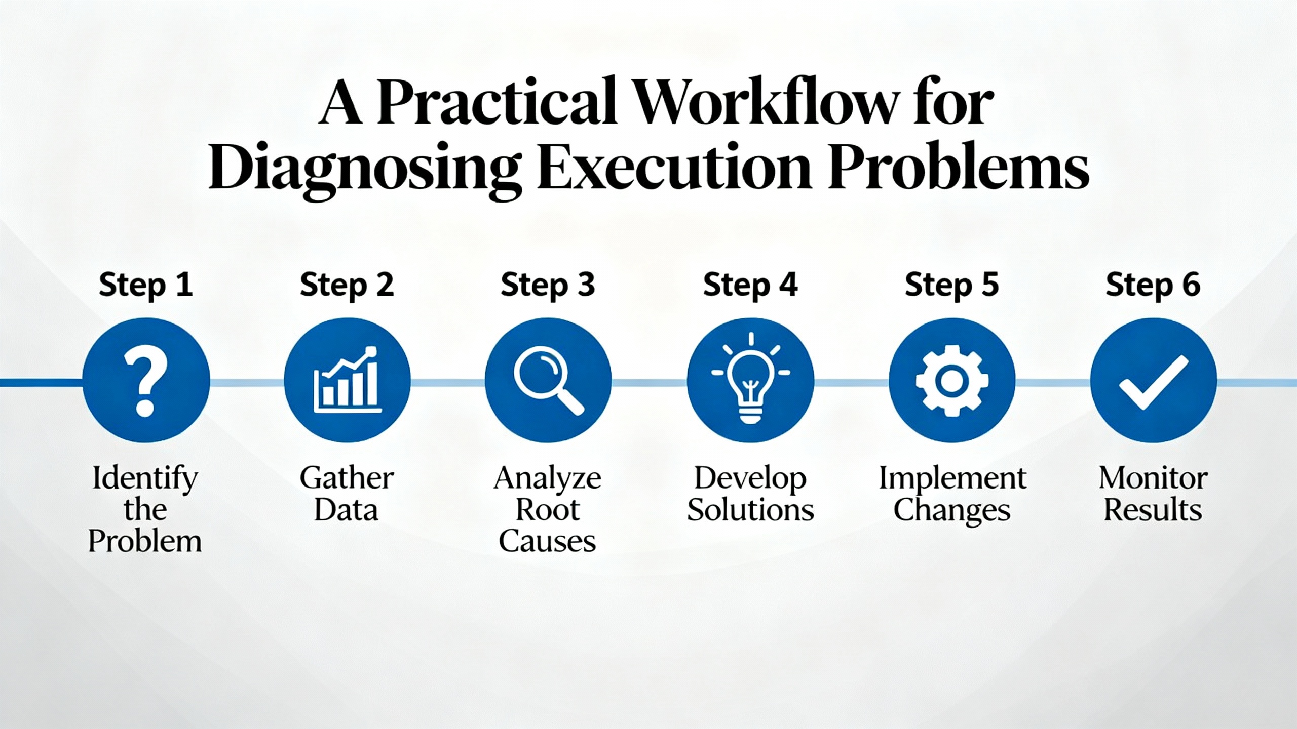
Experienced technicians and industrial authors converge on a consistent troubleshooting workflow. The steps are power, status indicators, I/O behavior, program logic, communication, hardware, reset, and only then vendor support. Applied specifically to Mitsubishi PLC program execution problems, that workflow looks as follows.
Before blaming the program, make sure the PLC is actually healthy enough to run one. MitsubishiŌĆæoriented troubleshooting articles start with the basics: check that the power cable is secure and undamaged, confirm that supply voltage matches the PLC rating, verify that any fuses are intact, and ensure the power module is not failed. General PLC guides from industrial suppliers stress the same points and add that loose connections, low voltage, overheating power supplies, and excessive AC ripple can all prevent a CPU from running reliably.
Power disturbances do more than shut a PLC off. They can scramble memory, trigger brownouts that look like random resets, and aggravate electrical noise problems. Academic discussion of PLC failures highlights blackouts, poor grounding, and EMI as sources of memory corruption and erratic behavior. In other words, if you see unexplained program stops, make a quick but thorough power check part of your first pass.
Once you know the PLC has solid power, look at the RUN and ERROR indicators and mode switches. Mitsubishi troubleshooting checklists explicitly call out the need to verify that the RUN indicator is on, that the physical mode selector (if present) is in RUN rather than STOP, and that the PLC is not being held in a forced stop by the programming software.
If the PLC refuses to enter RUN, connect with GX Works2, GX Developer, or other supported software and read the status and error flags. A flashing ERROR LED paired with an error code that points to a program fault tells you that you are dealing with logic or data. A solid ERROR LED with a CPU or expansion fault code suggests hardware. The Do Supply troubleshooting flow recommends also noting any ALARM or BATT LEDs at this stage, because they may indicate executionŌĆætime problems or memory retention issues that directly affect program execution.
Field advice from FX users is especially blunt in one area. If a machine has run reliably for years with the same program and suddenly starts showing watchdog timer errors and solid error lights without any logic changes, suspect hardware before you rewrite code. That does not mean software is always innocent, but it does mean you should not spend three hours rewriting a program that has been stable for a decade while a dying CPU fan or failing capacitor trips the watchdog timer over and over.
With basic status in hand, dig into the PLCŌĆÖs own diagnostics. Online PLC diagnostics and errorŌĆælog review are repeatedly described as the first real step in Mitsubishi FX troubleshooting. When you connect, pull the current error code, the error history if available, and any watchdog or scanŌĆætime information.
On FX series PLCs, repair guides recommend interpreting ERR 0001, 0002, and 0003 as CPU, communication, and memory problems respectively. Academic texts on PLC troubleshooting emphasize using manufacturer fault code tables to move from a raw code to a specific failure mode and then to a concrete corrective action. Community experts on FX2NC stress that you will often get better diagnostic detail by connecting with GX Developer than by relying on an older display module that might only show a generic ŌĆ£errorŌĆØ message.
The key is to let the PLC tell you what it thinks is wrong. A divideŌĆæbyŌĆæzero fault will show up very differently from a memory parity error. A communication timeout between modules is a different problem from a watchdog timer failing because your program never finishes the scan.
Many ŌĆ£program execution problemsŌĆØ turn out to be issues in the input or output path. A well structured article on PLC error types describes diagnosing ŌĆ£program not executingŌĆØ errors along the chain of input, program execution, and output. The method is straightforward. Check whether the input LEDs or monitors change when the field device actuates. Then check whether the program sees those changes and drives the relevant internal bits. Finally, check whether output LEDs and loads respond.
When the input and internal logic are both true but the output never energizes, you have a classic case of logic being overridden. A Mitsubishi PLC forum example shows X and Y contacts both true in online monitor mode while output coil Z remains off. Forcing the coil on makes the output work, confirming that wiring and hardware are fine. The root cause in such cases is often a forced OFF state applied earlier for testing and forgotten. In Mitsubishi tools, ŌĆ£forcingŌĆØ means manually overriding an I/O point or coil state so it ignores normal ladder conditions. The fix is to use diagnostic functions such as Device Test to view and clear any forced devices, and then ensure that the ladder logic itself does not intentionally drive the coil off elsewhere.
Field references also note that when only some program segments fail to execute, timing can be the culprit. For example, step controllers and counters may require input signals to be present for at least the moduleŌĆÖs maximum response time plus two scan cycles. If inputs are too brief, those segments effectively never execute from the programŌĆÖs point of view, even though the PLC as a whole is running.
Once basic hardware and I/O behavior are understood, move into the logic. Mitsubishi troubleshooting articles advise checking for syntax and logic errors, confirming that the intended program has actually been downloaded, and verifying that no required program blocks have been deleted or modified. General PLC programming guidance from books and practiceŌĆæoriented articles stresses modularizing code, handling abnormal conditions explicitly, and validating the sequence of operations.
In the context of Mitsubishi FX PLCs, forum and maintenance sources identify several specific logicŌĆælevel risks. DivideŌĆæbyŌĆæzero instructions where the divisor register can be zero will produce errors and NAN values. Long loops or poorly structured jumps can cause scan times to grow until the CPUŌĆÖs watchdog timer trips. Missing or inconsistent interlocks can allow states where the program appears to hang because key rungs never go true.
This is where online monitoring shines. Step through ladder sections while the machine is in a safe state and watch which rungs execute, which timers count, and which outputs change. CrossŌĆæcheck what you see against the design intent or process description, not just the code itself. And if you find that the program running in the PLC does not match the master backup, follow the advice from troubleshooting flowcharts by reloading the correct file and then updating your backups so the discrepancy does not return.
MitsubishiŌĆæspecific guides and general PLC references agree that memory problems are a distinct category. Mitsubishi troubleshooting content refers to storage issues where there is insufficient PLC memory or data loss, recommending cleaning up unused program blocks and data and replacing damaged storage media as needed. FX errorŌĆæcode documentation calls ERR 0003 a memory error and suggests reinitialization, module upgrade, and reset after backups.
Academic and industrial sources describe how power failures, noise, poor grounding, and excessive heat can corrupt PLC memory and user programs. Corrupted memory can make code unreadable or unexecutable, producing program execution errors even though the ladder logic was written correctly. In such cases, the recommended practice is to maintain current backups of programs and data on reliable external storage kept away from electrical noise and environmental extremes. When corruption is suspected, the sequence is to identify and correct the root cause, restore the program from backup, and then validate operation.
On PLCs with backup batteries, a dedicated BATT LED often signals a lowŌĆæbattery condition that threatens memory retention during power outages. While the Mitsubishi documents summarized here do not provide battery specifications, general PLC troubleshooting references urge prompt battery replacement when that indicator is lit, followed by verification that programs and data remain intact across power cycles.
It is easy to confuse a communication failure with a program execution error. If your HMI, SCADA, or engineering workstation cannot talk to the Mitsubishi PLC, the process will look ŌĆ£deadŌĆØ even if the CPU is executing normally.
Both MitsubishiŌĆæfocused and vendorŌĆæagnostic troubleshooting articles recommend a similar communication check. Confirm that cables and connectors are secure and undamaged. Make sure the communication lines are wired correctly and that any switches or routers in the path are operating. Verify that communication parameters such as protocol type, baud rate, station number, and addressing are consistent between the PLC and the other device. For host computer links, repair authors suggest updating the communication drivers if needed and matching them to the specific PLC model and firmware.
On FX PLCs, ERR 0002 is described as a communication error, and on some older FX units the dedicated display does not show full diagnostic detail. In those cases, the advice from experienced users is to rely on the programming softwareŌĆÖs diagnostics for a full picture of port health, error counters, and timeouts.
When program logic, memory, and communication all check out but the CPU still will not execute reliably, hardware moves to the top of the suspect list. Articles on Mitsubishi PLC faults divide failures into hardware and software categories and list core hardware elements such as power control boards, I/O control boards, and program control boards. Technicians in those references use two main methods. The first is experienceŌĆæbased elimination, where observed symptoms are matched with likely boards or modules based on prior field failures. The second is replacement, where a suspected module is swapped with a knownŌĆægood unit of the same specification to see whether the fault moves.
In Mitsubishi FX2N and FX2NC series, which are now endŌĆæofŌĆælife, community experts point out that a solid ERROR LED, intermittent communication loss, and watchdog timer faults on longŌĆærunning machines are often internal hardware problems rather than new programming defects. They encourage checking whether the PLCŌĆÖs internal 24 V supply has been overloaded by external sensors or field devices, because such overloading can destabilize the PLC itself. If power loading is acceptable and no wiring shorts are found, they recommend treating the issue as a failing CPU and planning a replacement, often to newer families such as FX3U or FX5U that provide modern hardware support and improved reliability.
Beyond the CPU, general PLC troubleshooting material discusses I/O or expansion unit abnormalities and recommends checking connector seating, cabling, and module status LEDs, then replacing the specific faulty unit if confirmed. Diagnostic tools are used to assess hardware status, but ultimately replacement is the definitive test.
Resetting a PLC can be a powerful tool or a dangerous impulse. Mitsubishi troubleshooting guides list reset toward the end of the workflow, after power, indicators, I/O, logic, communication, and hardware have been checked. Typical sequences involve powering the PLC off, waiting a short period, powering it back on, and seeing whether a transient error clears. If deeper problems persist, some FX repair sources suggest factory resets or complete memory clears followed by program reloads.
Industrial articles emphasize that you should never reset or clear memory until you have good backups of all programs and parameters. they recommend regular backups specifically to mitigate storage failures and data loss. Several sources also highlight that certain memory errors and program loss after brief power outages can indicate failing backup batteries, increased leakage current in memory devices, or noise from heavy machinery. In those situations, a reset without addressing the root cause will only buy temporary relief.
Finally, when all reasonable steps have been taken, Mitsubishi support or your equipment supplier becomes the right next move. The most efficient way to engage them, as described in Mitsubishi troubleshooting material, is to provide the PLC model and serial number, error codes or exact fault symptoms, and a clear summary of the troubleshooting steps already attempted.
Looking across MitsubishiŌĆæspecific and general PLC references, the same root causes show up repeatedly in program execution failures.
Programming and design mistakes are common. These include divideŌĆæbyŌĆæzero arithmetic, logic that never allows certain rungs to energize, and poor handling of abnormal conditions. Some program segments never run because inputs are too brief relative to scan time. Poor planning, inconsistent coding practices, and weak documentation all increase the likelihood of such mistakes, which is why process documentation, standard naming conventions, extensive commenting, and code reviews are repeatedly emphasized in PLC programming bestŌĆæpractice articles.
Data and memory issues are another frequent source of problems. Registers that hold unexpected NAN values, corrupted user programs, or insufficient memory for new program blocks can all cause erratic execution or outright stops. Industrial guidance links these failures to noise, poor grounding, power disruptions, and failing memory hardware. Preventive measures include cleaning up unused data, maintaining backups, and replacing damaged or suspect memory devices.
Power, noise, and environmental stress play a larger role than many new engineers expect. Technical articles on PLC troubleshooting describe power supply faults, excessive heat, dust accumulation, and electromagnetic interference as major contributors to CPU alarms and execution problems. For Mitsubishi PLCs, this shows up as overheated CPUs, dirty or blocked cooling paths, and interference from nearby highŌĆæpower equipment causing unstable signals. Recommended actions include keeping PLCs in well ventilated enclosures, cleaning dust, ensuring that they are kept within manufacturer temperature limits, and using shielded cables and proper grounding where interference is present.
Hardware aging and endŌĆæofŌĆælife status cannot be ignored. Older Mitsubishi FX2N and FX2NC CPUs in longŌĆærunning machines are more likely to suffer internal component failures, leading to intermittent watchdog errors, solid error LEDs, and random program halts. Field experts stress that once you have ruled out power, wiring, and obvious configuration mistakes, it is often more effective to plan a hardware upgrade to a current FX family than to repeatedly patch a failing legacy CPU.
Finally, software versions and security form a quieter but growing category. Mitsubishi troubleshooting content acknowledges that outdated or incompatible software versions can cause problems, and broader PLC literature highlights configuration and security mistakes as risk factors for both failures and malicious interference. In heavily regulated sectors such as nuclear power, PLCŌĆæbased systems are governed by standards that demand rigorous verification and validation of both hardware and software. For most factories, the practical lesson is simpler. Keep track of firmware and engineering software versions, manage changes deliberately, and configure security settings so that only authorized staff can alter PLC programs and parameters.
The most effective way to handle Mitsubishi program execution problems is to prevent them where you can. Technical textbooks on PLC design and application emphasize structured approaches to sequential control problems, modular program organization, and standardized code patterns. Practical articles on programming errors highlight process planning, consistent naming, thorough commenting, and peer review as the first line of defense.
In a Mitsubishi context, structured design means converting process specifications into clear tasks, then breaking those tasks into manageable routines. For example, separating motion sequences, safety interlocks, and communication handling into distinct program sections makes it much easier to troubleshoot later. When a watchdog timer trips, you do not want to hunt through a single monolithic block; you want to examine each logical function, see its impact on scan time, and test it independently.
Standardized programming practices pay off when you return to a job months or years later, or when another engineer has to support your code. Articles on preventing PLC programming errors advocate consistent tag and variable naming so that inputs, outputs, and internal bits are immediately recognizable. They also stress meaningful comments that capture not just what the code does, but why, so that future modifications do not accidentally remove critical conditions.
Regular code reviews bring fresh eyes to the problem. Reviewers can find logic paths that never execute, race conditions that depend on exact scan timing, or arithmetic constructs that may divide by zero under certain operating conditions. In many plants, pairing code reviews with simulated or dryŌĆærun tests before deployment dramatically reduces executionŌĆætime surprises.
Training and continuous learning also feature strongly in the literature. As PLC platforms evolve and new Mitsubishi families replace older ones, engineers must stay current with programming tools, diagnostics, and manufacturer guidelines. Structured training texts and courses frame troubleshooting as part of a larger engineering process, not a separate skill, integrating design, commissioning, and maintenance.
Backups, documentation, and change control round out the picture. Multiple sources recommend maintaining detailed documentation of PLC configurations, firmware versions, program revisions, and repair history. Keeping this information organized allows you to reconstruct what changed between a stable system and one that now experiences execution errors. It also aligns with broader recommendations from safetyŌĆæcritical fields, where regulators require proof that PLC software and hardware have been validated and maintained under controlled processes.

Program execution problems often surface at the worst possible time: late in the shift, with production behind schedule. That is exactly when shortcuts become tempting. Every Mitsubishi and vendorŌĆæneutral troubleshooting reference, however, returns to the same principle. Always follow safe operating procedures. Power down the equipment before performing wiring or hardware checks. Even with lowŌĆævoltage control systems, improper work can cause electric shock, damage components, or create new latent faults.
When your own methodical troubleshooting reaches its limits, do not hesitate to involve Mitsubishi technical support or your equipment supplier. Be ready with the PLC model and serial number, the exact error codes or LED patterns, a description of the operating conditions when the failure occurs, and a list of steps you have already taken. Detailed, precise symptom descriptions dramatically improve the odds that remote experts can give you a useful diagnosis instead of generic advice.
For chronic problems on aging hardware, especially older FX series units that are no longer manufactured, you should also be prepared to recommend a structured replacement project. Upgrading to a current Mitsubishi family with modern diagnostics, better support, and improved reliability is often the most costŌĆæeffective longŌĆæterm solution to recurring execution faults.
Start with LEDs and error codes. A flashing ERROR LED with codes that point to logic or arithmetic faults usually means software, while a solid ERROR LED combined with CPU or expansion module alarms and longŌĆæterm stable code strongly suggests hardware. Then trace inputs to outputs; if logic transitions properly but outputs do not respond until forced, you are probably dealing with forcing or hardware, not basic program structure.
Common reasons include inputs that pulse faster than the PLC and its I/O can detect, misordered logic that never lets conditions go true, and hidden forced states that hold devices on or off regardless of the program. Following the inputŌĆæprogramŌĆæoutput chain with online monitoring, and checking for forced devices in the diagnostics, usually reveals where execution is being blocked.
If an FX PLC has run the same program for years, and you now see persistent watchdog timer errors, solid ERROR LEDs, and intermittent communication or power instability even after verifying wiring, power, and program integrity, you are likely dealing with aging hardware. In such cases, field experience and maintenance articles recommend planning a migration to current Mitsubishi models rather than investing heavily in repairing an endŌĆæofŌĆælife CPU.
In the end, troubleshooting Mitsubishi PLC program execution errors is about discipline, not heroics. Read the indicators, respect the error codes, follow a consistent workflow, and treat design and documentation as part of troubleshooting, not an afterthought. That is how you keep lines running, operators safe, and your PLCs doing their job instead of becoming the bottleneck.


Copyright Notice © 2026 mooreautomated.com All rights reserved,Moore Automated is not an authorized distributor or representative of the manufacturers featured on this website. Brand names and trademarks featured are the property of their respective owners.


Leave Your Comment