


MP 3009X
Get A Quote
When an Omron PLC goes down, the plant does not care whether the fault is in firmware, field wiring, or a tired power supply. From the operatorŌĆÖs point of view, the line is stopped, product is not moving, and the clock is ticking. As an engineer who spends a lot of time in front of real panels with Omron hardware, the fastest wins come from a structured method that respects how these controllers are built and how they fail in practice.
This guide distills practical troubleshooting patterns drawn from OmronŌĆÖs own technical guides, field-oriented resources such as Industrial Automation Co. and PLC Department, academic work by Joji Parambath, and real hardware build examples from DigiKey TechForum and other practitioners. The focus is on Omron PLCs in machine and factory automation, but the mindset applies broadly across platforms.
The goal is simple: give you a step-by-step way to get from symptom to root cause without guesswork, while protecting people, equipment, and production schedules.
Omron supplies a wide range of PLC families, from compact micro-PLCs to large modular racks. Application-oriented overviews such as those from RealPars show CP-series controllers like CP1E, CP1H, CP1L, and CP2E used in compact machines and small conveyor systems, while CJ2M and CS1 platforms support higher I/O counts and more complex processes with features like structured text, motion control, and redundant CS1D CPU configurations.
Older C200H platforms have largely been replaced by CS and CJ series, but as Omron users on community forums point out, many plants still run mixed systems. C200H I/O cards can be reused on CS1 processors with appropriate racks, and OmronŌĆÖs CX-Programmer can convert much of the old logic, with some manual cleanup required around specialty modules. In practice this means you may find a C200H rack bolted next to a newer CJ or CS system, and you need to be comfortable reading both.
The takeaway is that Omron hardware is modular and layered. A given cabinet typically contains a power supply, CPU unit, I/O modules, and communication cards, along with field power supplies and terminals. When you troubleshoot, you are never just fixing ŌĆ£an Omron PLCŌĆØ; you are checking how these pieces interact under real load.
OmronŌĆÖs PLC Technical Guide 26 and related explanation-of-terms material clarify how CPU memory is organized. The CPU Unit stores several categories of data: user programs, I/O memory data that tracks process state, comments, CPU and Special I/O Unit parameters, and registered I/O table information. All of this lives in defined memory areas, and those areas do not behave the same way on power-up, fault, or battery failure.
The User Program Area holds the control program itself. I/O Memory Areas hold operational data and are directly accessed by instruction operands in ladder or structured logic. Omron breaks I/O memory into sub-areas such as the CIO Area, Work Area, Holding Area, DM and EM Areas, Timer and Counter Areas with completion flags and present values, Task Flags, Index and Data Registers, Auxiliary Area, and various condition flags and clock pulses. Some of these areas are retentive through power cycles, some are not, and some are configurable.
The Parameter Area holds initial configuration such as PLC setup, I/O tables, routing tables, and CPU bus unit settings. For CS/CJ series, user programs and parameter areas are stored in flash memory in addition to battery backup, so a low battery will not automatically erase logic or configuration. Understanding which pieces of data survive a power cycle and which are cleared is crucial when you see a machine that ŌĆ£worked yesterdayŌĆØ but now starts up in a different state.
You do not need to memorize every area, but you should know the difference between program, I/O memory, and parameter settings. That difference tells you whether a symptom is likely to come from logic, live process conditions, or configuration.
Realistic troubleshooting has to match the panel in front of you. A demonstration enclosure described on DigiKey TechForum for an Omron CP2E-N30DR-D is a good example of clean design that simplifies diagnosis. In that panel, DIN rail and raceway are laid out so that power distribution, inputs, and outputs are clearly separated. Terminal blocks are grouped for mains power, 24 VDC distribution, PLC inputs, and PLC outputs. Wire gauges are chosen deliberately: 14 AWG for 120 VAC and protective earth, 16 AWG for 24 VDC and I/O. Every termination is labeled using a wire-marker printer, with legends such as Live, Neutral, 24VDC, 0VDC, channel ranges, and NET.
The CP2E PLC in that build has eighteen digital inputs and twelve relay outputs. Inputs share a common that can be tied to the positive or negative 24 VDC rail. Outputs are grouped with distinct commons, and the front panel LEDs clearly show which inputs and outputs are active. Sensors, such as an NPN E3FA photoelectric device, are wired according to the chosen common polarity, and tower lights are wired to outputs with appropriate resistors to adjust alarm volume.
Panels in production facilities rarely look as textbook-clean as a demonstration enclosure, but the same principles apply. Clear physical separation of power and signals, correct wire sizes, proper labeling, and obvious I/O grouping make troubleshooting much faster. When you open a cabinet and see the opposite, you know you will spend more time tracing wires than analyzing logic.

Technical guides, field blogs, and academic material converge on a common message: do not jump straight into the ladder editor. A disciplined sequence will save you more time than any shortcut. Resources from PLC Department, Industrial Automation Co., and Joji ParambathŌĆÖs troubleshooting chapter describe essentially the same path.
Before touching anything, secure the machine. For module-level work, best practice described by automation vendors is to isolate power and apply lockout/tagout so that no unexpected motion or energization can occur. Confirm with operators what the machine was doing at the time of failure, whether there were any alarms on the HMI, and whether someone recently changed a program, parameter, or wiring. This ŌĆ£operator interviewŌĆØ often reveals clues about intermittent faults or changes that preceded the event.
At the same time, look at the process: Are valves stuck mid-position? Are conveyors full or empty? This context will later help you interpret what the PLC logic is trying to do when you go online.
Industrial Automation Co. emphasizes that PLCs are critical assets and should be maintained through regular checks of power, cleanliness, and environment. For troubleshooting, you compress those checks into a quick diagnostic sweep.
Confirm that the PLC and its field power supplies are receiving the correct voltage and that any upstream circuit breakers or fuses are intact. If you have an Omron system that seems completely dead, remember that many symptoms trace back to simple switch-mode power supply failures. A field-oriented article on Omron PLC power supplies notes frequent failure of fuses, ACŌĆæDC converter ICs, and electrolytic capacitors. Visual inspection can reveal heat damage or bulging capacitors. Electrical measurement with a meter will confirm whether the PLC actually sees the expected supply.
While you are at the panel, scan for dust buildup, moisture, or signs of overheating. Excess heat and vibration are well-known contributors to intermittent PLC failures. Joji Parambath highlights the role of environmental stresses and electrical noise in scrambling memory and causing nuisance faults. If the panel is crammed against hot equipment or packed with unventilated drives, make a note; even if it is not the root cause today, it will be a recurring risk.
Modern PLCs, including Omron units, are generous with indicators. CPU, power, I/O, and communication modules all carry LEDs that are there for your benefit. Troubleshooting guidance from PLC Department and Joji ParambathŌĆÖs work both stress using these first.
Note the state of CPU RUN, ERROR or ALARM, communication status, and individual input and output channel LEDs. Compare LED states to what the process is supposed to be doing. If input LEDs are dead even though sensors are actuated, you have an input-side problem. If input LEDs change but corresponding output LEDs stay off, you are either missing logic conditions or dealing with inhibited outputs.
Omron manuals and technical guides provide tables of LED meanings and error codes. While this article does not reproduce specific codes, the method is straightforward: match the observed pattern to the manufacturerŌĆÖs troubleshooting table, which will suggest probable causes and recommended actions such as checking I/O buses, memory integrity, or communication settings.
Several Omron-focused troubleshooting notes insist on breaking the system into input and output sides. KwocoŌĆÖs general guidance on Omron PLC systems describes two typical flows. On the input side, you verify that field devices are powered correctly, wired to the right terminals, and that PLC input LEDs and memory bits follow the device state. On the output side, you confirm that output coils in the program are being energized and that output LEDs and field voltages follow those bits.
A real-world example comes from a forum case involving an Omron Sysmac C40K controlling directional valves. The operator could see that pushing a button lit the corresponding input LED on the PLC, but most valves did not move. Only one out of roughly nine valves responded properly. That tells you immediately that inputs are reaching the PLC while outputs or field devices are not behaving.
In such a situation, the first step is to go online with the PLC and watch the output instructions tied to those valves. If the logic does not attempt to energize them, you have a program or interlock issue. If the logic does energize them and the PLCŌĆÖs output LEDs turn on, the problem lies between the module terminal and the coil: wiring, power to the load, common referencing, or the valve solenoid itself. Checking for blown fuses, miswired commons, and missing supply to the valve cluster is often enough to find the fault.
Once the basics are checked, it is time to connect a laptop. OmronŌĆÖs CX-One suite, particularly CX-Programmer, is the standard environment for many Omron PLC families. Users on Omron forums recommend it for its flexibility, including extensive keyboard shortcuts and the ability to monitor logic live. CX-Simulator can emulate PLC behavior in some situations, although it cannot simulate every specialty I/O card.
From a troubleshooting perspective, you use these tools to go online, read error logs and alarms, and monitor key registers and bits. For Omron CPUs, diagnostic logs and error codes are available through the software. KwocoŌĆÖs generic troubleshooting notes emphasize reading error information, distinguishing minor alarms such as low battery from fatal errors such as I/O bus faults or memory corruption.
In ladder, you can watch key rungs, timers, and interlocks while forcing conditions in a controlled manner. For example, you might temporarily force an input bit on to see whether an output coil would energize in the current state. For test programs, it is common practice to load a simple piece of logic that drives a single output or input pattern to determine whether a suspected module or field device behaves correctly, always observing safety and ensuring the machine cannot move unexpectedly.
Guidance derived from module-level troubleshooting articles and Industrial Automation Co. suggests a systematic hardware isolation strategy. When an output card appears faulty, reseat it and inspect the backplane connector. If issues persist, move the module to another slot if the platform allows it, or temporarily swap with a known-good spare. If the problem follows the module, the card is suspect. If it stays with the slot or rack, focus on backplane, power, or system configuration.
For inputs and outputs, use a meter to verify actual voltage or current at the terminal and compare it to what the PLC indicates. On an Omron analog module, ensure that the signal type and range match the moduleŌĆÖs configuration. For digital I/O, verify that commons are wired correctly, especially with NPN versus PNP sensors. The CP2E demonstration build shows how wiring the common to 24 VDC defines which sensors can be used and how they must be wired.
Communication problems between an Omron PLC and HMIs, drives, or remote I/O are very common in the field. KwocoŌĆÖs troubleshooting advice and PLC DepartmentŌĆÖs tips both recommend confirming that communication cables are intact and correctly pinned, that IP addresses or node IDs are set correctly, and that baud rate and protocol settings match at both ends. For Ethernet-based systems, a simple ping test or check of link/activity LEDs is an easy start. For proprietary industrial buses, rely on the PLCŌĆÖs diagnostic bits and the network adapterŌĆÖs status indications.
A strikingly common complaint in Omron-heavy plants is ŌĆ£the PLC powers on but nothing happens.ŌĆØ According to a detailed discussion of Omron PLC switch-mode power supply maintenance, many of these cases come down to the internal power supply rather than the CPU itself. Three components appear repeatedly in field failures: the primary fuse, the switch-mode power module, and an electrolytic capacitor used for voltage stability.
In practice, the troubleshooting path is straightforward. After ensuring safe conditions, inspect the supply board for obvious heat damage or discoloration. Check the main fuse for continuity. If the fuse is open, you must not simply replace it and hope; a blown fuse usually indicates a deeper fault such as a shorted converter module or severely degraded capacitor. Measure input and output voltages of the converter IC. If the module receives proper input but produces no output, or if outputs are unstable, the module is likely failing.
For capacitors, desoldering and measuring capacitance off-board will show whether the value has drifted significantly below its rating, which is common as electrolyte dries over time. When replacing components, the same source recommends keeping ratings identical or better: match the fuse type exactly, replace converter modules with the same model and voltage/current capability, and use high-quality capacitors with equal capacitance and equal or higher voltage rating, mounted away from heat sources.
After repairs, always perform a no-load test first. Power the supply with no PLC or field load attached and verify that voltages are stable and free of abnormal sounds. Then add load gradually. Successful component-level repair can return an Omron system to service without replacing the entire PLC, but this work should be done only by qualified personnel with appropriate test equipment and respect for mains safety.
The C40K directional valve case illustrates a widespread scenario: the PLC sees your command but does nothing with it. When pushbuttons light corresponding input indicators yet outputs remain off, the debugging path is fairly consistent.
First, confirm that the PLC is actually running and not in a stopped or program mode. Check RUN and ERROR indicators on the CPU. Next, go online and monitor the ladder rung that drives the affected outputs. Verify that the input bit you see on the front panel is mapped correctly in the program and that interlocks or safety conditions permit the output to turn on. In safety-critical machines, permissives from guards, emergency stops, or upstream processes may intentionally block outputs.
If the program energizes the output coil and the PLCŌĆÖs output LED also turns on, move your attention to field wiring. Use a meter at the output terminal to confirm the presence of voltage when the LED is on. Check that the loadŌĆÖs power supply is present and that commons are wired as expected. In hydraulic or pneumatic systems, shared common or power feeds to valve banks are easy to overlook. A single missing jumper can leave most valves dead while one or two, perhaps wired differently, still work.
Finally, verify the health of the load devices. Coils in directional valves, contactors, and relays can fail open. A simple resistance measurement across the coil terminals with power removed will show whether there is a conductive path. Always reconnect and label any wires removed during testing to avoid creating the next fault yourself.
Intermittent PLC problems consume disproportionate amounts of troubleshooting time because they appear, disappear, and often refuse to show themselves when you are watching. Joji ParambathŌĆÖs PLC troubleshooting chapter and OmronŌĆÖs own material on memory behavior highlight several contributing factors: noisy power, poor grounding, electromagnetic interference from large motors, and excess heat.
In Omron racks installed close to high-power drives or large motor starters, electrical noise can couple into I/O, communication lines, or even power supplies. Symptoms range from occasional false input transitions to watchdog trips or communication timeouts. Mitigations described in field and academic sources include ensuring that all protective earth connections are intact and continuous, using shielded cables for analog and network lines with shields terminated properly at one end, separating low-level signal wiring from high-power conductors, and adding surge suppressors or noise filters where necessary.
Loose terminals and aging connectors are another frequent cause. Industrial Automation Co. recommends routine inspection and tightening of connections, cleaning corrosion with appropriate contact cleaner, and verifying grounding and shielding. When you see intermittent behavior in one channel or module, gently moving the wiring while monitoring status bits online can sometimes reveal bad crimps or loose terminals.
Communication problems often masquerade as PLC problems. A stalled HMI may lead operators to report that ŌĆ£the Omron PLC is frozen,ŌĆØ when in reality the controller is running and only the network path is broken.
General guidance from Kwoco and PLC Department suggests a simple triage. Check physical indicators on Ethernet switches, PLC ports, and devices. Confirm that cables are undamaged and firmly seated. Verify that IP addresses or node IDs, subnet masks, and baud rates match the required configuration. In Omron systems using networks like Ethernet/IP, CompoBus/S, DeviceNet, or Profibus-DP, refer to the Omron manuals for specific diagnostic LEDs and status flags that indicate online, connection error, or configuration mismatch conditions.
Use OmronŌĆÖs engineering software to check whether you can go online with the PLC. If you can, the CPU is alive. Many Omron CPUs also expose network diagnostics that show which nodes are connected and any historical errors. Use that information to narrow down whether the problem lies in cabling, configuration, or a specific device.
The most elegant ladder diagram cannot save a system from bad power or poor installation practices. Across resources from Omron, Industrial Automation Co., and community forums, three themes appear again and again: power quality, grounding, and environmental conditions.
OmronŌĆÖs technical and support material point out that sudden power losses and bad wiring can scramble memory and cause process data loss. Industrial Automation Co. recommends surge protection and uninterruptible power supplies for PLCs that must ride through brief outages, along with keeping panels dry, dust-free, and within specified temperature limits. Joji Parambath adds that excess heat and vibration shorten module life and contribute to intermittent faults that are hard to reproduce.
The article on Omron PLC switch-mode power supplies shows how neglected electrolytic capacitors drift over time, leading to poor voltage regulation and increased stress on other components. It also illustrates the importance of mounting sensitive parts away from heat sources. In the field, that translates into leaving space around PLC racks for airflow, not stacking power supplies directly above hot drives, and ensuring that fans and filters are maintained.
Proper grounding is not just a safety requirement; it is essential for stable PLC operation. All ground wires should be continuous and correctly installed. Ground loops, where multiple paths to earth create circulating currents, can induce noise into analog signals and communication lines. Troubleshooting guidance for Omron modules suggests that separating control ground from noisy power ground, and routing signal cables away from high-current paths, reduces these problems significantly.
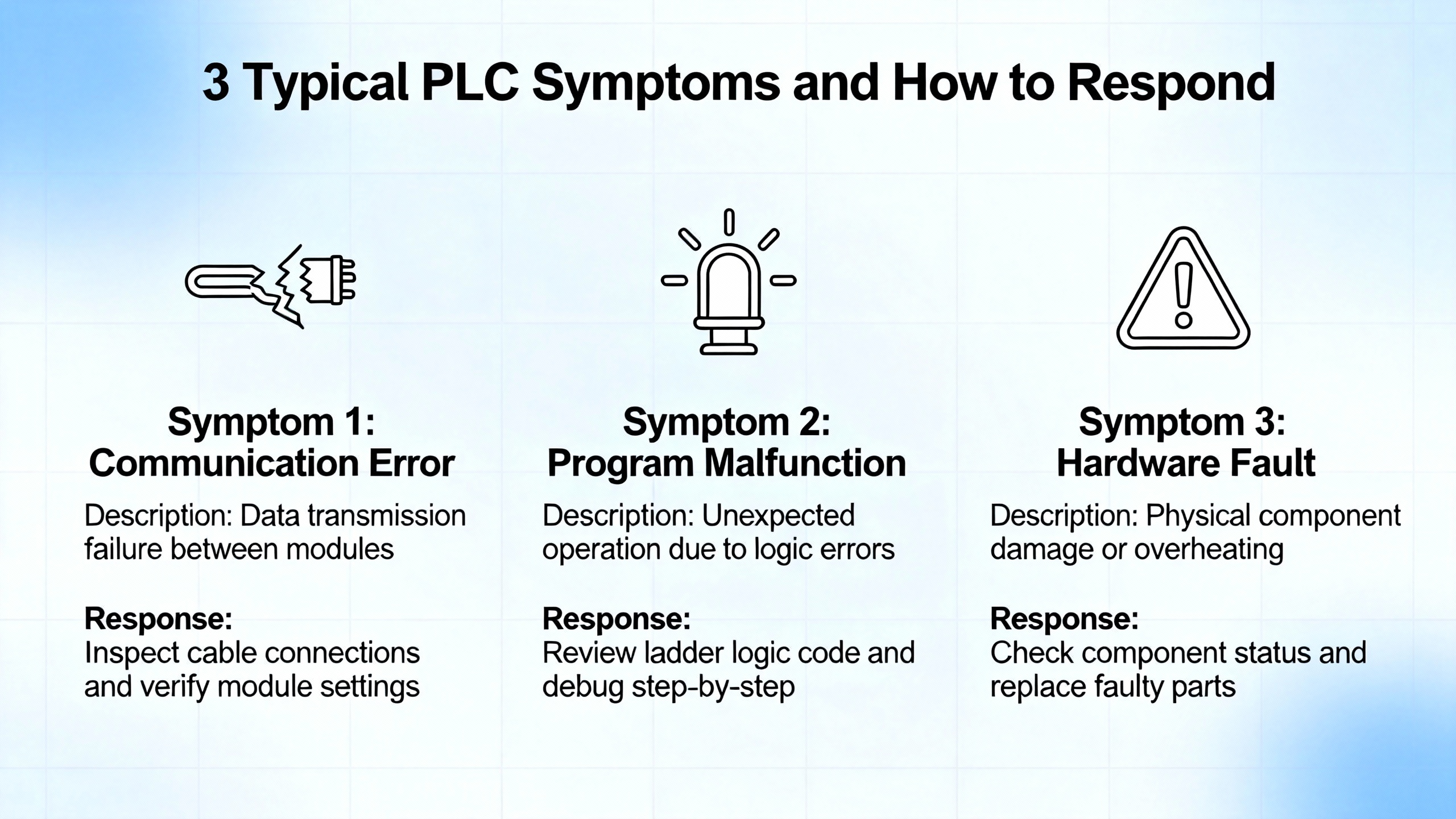
A small comparison table highlights how symptoms often map back to these foundational issues.
| Symptom | Likely Area To Investigate |
|---|---|
| PLC intermittently stops or resets | Power quality, loose supply wiring |
| Random input changes with no real process change | Sensor wiring, grounding, EMI noise |
| Analog readings drift or jump | Shielding, grounding, cable routing |
| Repeated module failures in one panel section | Heat buildup, vibration, power spikes |
Using this lens keeps you from over-focusing on code when the real culprit is a failing supply, hot enclosure, or noisy installation.

Omron invests heavily in documentation and support. Taking advantage of those resources significantly reduces troubleshooting time.
OmronŌĆÖs PLC Technical Guide 26 and the explanation-of-terms pages provide foundational definitions for memory areas, parameter storage, and system behavior. Knowing how CIO, DM, and parameter areas behave under power cycles and errors helps you interpret what you see online. OmronŌĆÖs global technical support site offers manuals, application guides, and troubleshooting information targeted at manufacturing users. Community advice suggests obtaining OmronŌĆÖs digital technical library, which consolidates product manuals, and using third-party sites that host example code and learning material.
On the software side, CX-One with CX-Programmer is the main configuration and programming environment for many Omron platforms. Experienced users highlight its keyboard-driven workflow and integration with network and HMI tools. CX-Simulator allows offline testing of logic for some CPUs, which can be helpful when you need to reproduce conditions in a safer environment. For newer NJ/NX series and integrated automation architectures, Sysmac Studio serves a similar role with motion and safety integration, although detailed content from that manual was not available in the notes.
Whatever tool you use, the key is to treat it as a diagnostic instrument rather than only a programming editor. Use watch windows, tracing, and live monitoring of bits, timers, and register values while the machine is running or in a controlled test mode. Document error codes and timestamps. Export and archive programs and parameter sets before making changes so that you can roll back if needed.

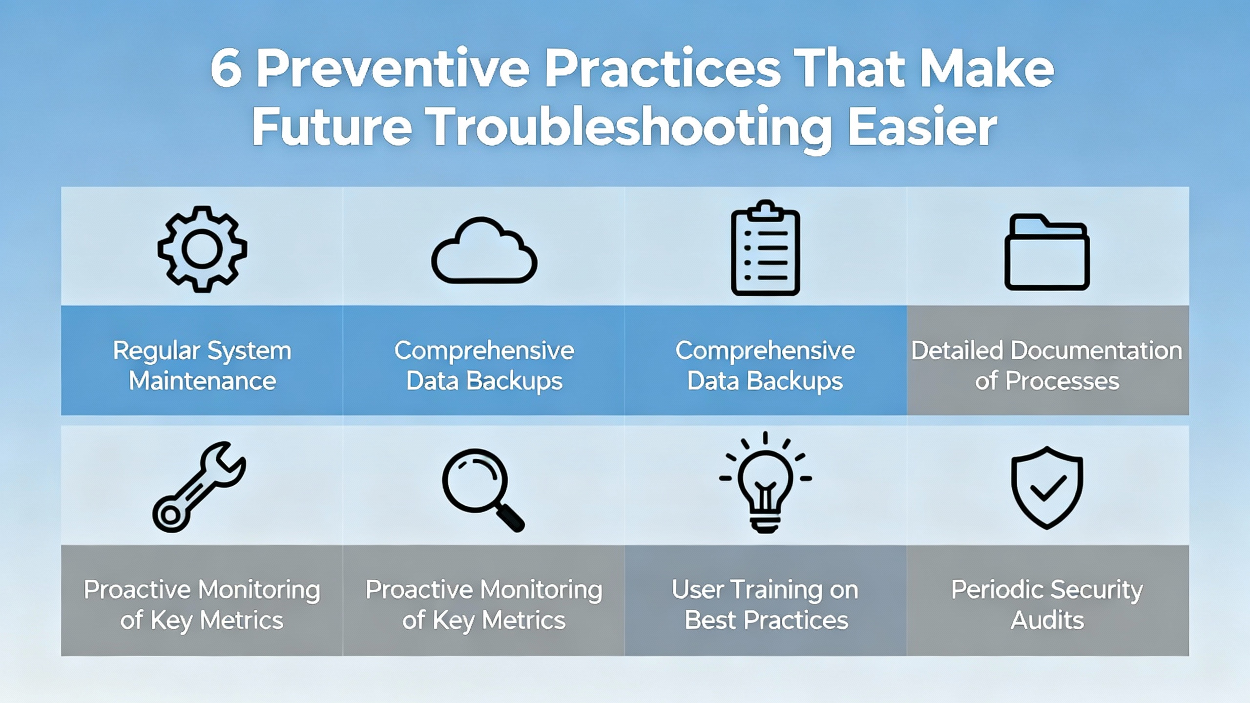
Troubleshooting is always easier on a well-maintained system. Several sources converge on preventive habits that pay off repeatedly in Omron environments.
Industrial Automation Co. recommends establishing a formal maintenance schedule tailored to the workload and environment, including frequent visual inspections, periodic logic checks, and annual comprehensive reviews. During inspections, technicians should look for loose wiring, signs of overheating, dust accumulation, and any obvious physical damage.
Regular cleaning of electrical connections, tightening terminals, and verifying grounding and shielding reduce the risk of intermittent issues and noise. Replacing backup batteries at manufacturer-recommended intervals prevents surprises from program or data loss on platforms that still rely on battery backup.
Keeping firmware and software up to date is another important theme. Industrial Automation Co. advises updating PLC firmware and related software using official releases only, always backing up programs and settings beforehand and testing thoroughly afterward. For Omron systems, that means using OmronŌĆÖs official tools and release notes.
Backup practices deserve special attention. A robust backup strategy includes regular automated backups of PLC programs and critical data, stored both on-site and off-site, as well as periodic tests of restore procedures. When a CPU fails outright, having a current, verified program and parameter set can turn a multi-hour recovery into a short swap and download.
Finally, training matters. Both Industrial Automation Co. and PLC Department emphasize educating operators and maintenance staff on how PLCs work, how to read basic diagnostics, and when to escalate. A technician who understands Omron memory areas, I/O mapping, and network basics will solve problems faster and introduce fewer new ones. Community-shared resources such as PLC handbooks and online guides, often circulated through professional groups, can supplement formal training.
A concise view of preventive actions and their impact looks like this.
| Preventive Action | Practical Benefit |
|---|---|
| Scheduled inspections and cleaning | Early detection of loose or overheated components |
| Firmware and software kept current | Fewer unexpected incompatibilities and bugs |
| Regular backups and tested restores | Fast recovery from CPU or memory failures |
| Battery and power supply maintenance | Reduced risk of data loss and no-boot conditions |
| Grounding and shielding verification | Less electrical noise and fewer nuisance faults |
| Staff training on PLC basics | Quicker, safer troubleshooting in day-to-day work |
Why does my Omron PLC show input LEDs changing but the machine does nothing?
This usually means the PLC is seeing your input devices but either the control logic is not commanding outputs or the commands are not reaching the field devices. Go online with the PLC and verify that the relevant output coils turn on in the program when inputs are active and interlocks are satisfied. If they do, confirm that output LEDs and terminal voltages change accordingly and that loads have correct power and common wiring. The directional valve example with an Omron C40K shows that often only one of several loads works because its wiring or supply is slightly different from the others.
What should I check first when an Omron PLC appears completely dead?
After ensuring safety and lockout, verify the incoming power to the PLC power supply or base. Many dead systems are traced to the internal switch-mode power supply rather than the CPU. Inspect for blown fuses, damaged converter modules, or aging capacitors as described in Omron power supply maintenance discussions. If you are not equipped for component-level work, replace the power supply or PLC with a known-good unit and see whether the system boots, then send the suspect unit for repair.
How can I reduce the time I spend troubleshooting recurring Omron PLC issues?
Invest in preventive practices. Keep panels clean and within temperature limits, maintain solid grounding and shielding, schedule regular inspections of wiring and modules, and back up PLC programs and parameters so you can recover quickly from hardware failures. Use OmronŌĆÖs documentation and tools to understand how your specific CPU handles memory areas and diagnostics, and train your team to read error codes and basic ladder logic. Over time, these habits shift your effort from firefighting to predictable maintenance.
When you stand in front of an Omron panel on a live production line, the difference between guesswork and a methodical approach is measured in hours of downtime. Use the hardware indicators, the engineering software, and the manufacturerŌĆÖs memory model together. Respect power, grounding, and environment as much as you respect the ladder diagram. Do that consistently, and Omron PLC troubleshooting becomes a structured engineering task rather than a painful art.


Copyright Notice © 2026 mooreautomated.com All rights reserved,Moore Automated is not an authorized distributor or representative of the manufacturers featured on this website. Brand names and trademarks featured are the property of their respective owners.


Leave Your Comment