


MP 3009X
Get A Quote


When a production line stops because “the sensor isn’t talking,” the plant does not care whether the root cause is a fieldbus configuration, a ground loop, or a dirty power supply. It just knows it is losing money by the minute. On site, I am usually called over to a panel where a Pepperl+Fuchs device is flashing an error and the HMI is full of alarms like “communication interference” or “network congestion.”
The good news is that most Pepperl+Fuchs communication faults follow repeatable patterns. By understanding how their error codes are structured, and by applying solid industrial networking and wiring practices, you can turn seemingly cryptic communication errors into an actionable checklist.
This article walks through how to interpret Pepperl+Fuchs sensor error codes, how to troubleshoot the communication path from sensor to PLC, and how to design your systems so these problems are less likely to return. The guidance is grounded in Pepperl+Fuchs documentation, vendor-neutral troubleshooting practices, and what consistently fixes problems for me on real factory floors.
Pepperl+Fuchs documentation and an Eltra Trade technical explainer show that their diagnostic codes fall into three broad families: sensor, communication, and power supply.
Sensor codes (often prefixed with something like SFERR) point to misinterpretation of data, hardware malfunction, or inconsistent readings. Communication codes (often prefixed with CEERR) point to interference, congestion, or device incompatibility. Power codes (often with PSERR prefixes) highlight voltage instability, interruptions, or surges.
In the field, these categories blur. A supply that drops under load may show up first as a communication timeout. A drifting sensor might be logged as a data integrity issue that looks like a protocol fault. So when you see a Pepperl+Fuchs “communication” error, treat it as the system telling you, “Somewhere between the sensing element and the controller, the data stream is not reliable,” and keep an open mind about where that failure might be.
The most productive mindset is to see these error codes as a starting point, not a verdict. They narrow the search area, but you still need to walk through the physical and logical layers methodically.
Pepperl+Fuchs-oriented guides organize typical codes into three groups. The following sections summarize how each group relates to communication problems.
Technical notes describe sensor-related codes such as sensor data misinterpretation, general sensor malfunction, and discrepancies in sensor readings. These tend to map to situations like:
Sensor data misinterpretation, where the field device is reading the environment but reporting values that do not match actual conditions. The root causes cited include environmental changes, calibration issues, wear, or internal component degradation. From a PLC standpoint, this often looks like a “communication” anomaly because values jump or freeze unexpectedly.
Sensor malfunction, where internal failures or connectivity issues inside the device prevent it from generating valid data. Documentation calls out internal electronics, field wiring, or environmental stress as common contributors.
Discrepancies in sensor readings, where apparent drift or conflicts between multiple sensors generate inconsistent data. The Pepperl+Fuchs material links this to calibration misalignment or sensor drift over time.
In practice, these faults frequently get reported as communication errors in HMIs and SCADA systems because the system sees “bad data” or “no data” rather than a neatly labeled sensor failure. When you see communication alarms coexisting with sensor drift or implausible values, you need to keep SFERR-type issues in mind even if the headline looks like communication.
Communication error codes documented for Pepperl+Fuchs devices include:
Communication interference and signal loss. The vendor literature describes this as interruptions or degradation in the data exchange between devices. In neutral industrial control system (ICS) guidance, similar symptoms are often traced back to cable damage, loose connectors, electromagnetic interference, or incorrect network topology.
Network congestion. This describes a saturated network where legitimate traffic competes and messages are delayed or dropped. Articles on industrial control troubleshooting explain how congestion can show up as slow HMIs, delayed command execution, or intermittent timeouts.
Device incompatibility. Pepperl+Fuchs documentation characterizes this as devices not speaking a common language on the network. Vendor-neutral sources describe similar problems arising from mismatched protocols, unsupported feature sets, or firmware that predates a bus master’s expectations.
These codes are the ones that truly live in the communication path, but you still cannot fix them by “tuning the network” alone. Physical wiring, grounding, and power quality remain foundational.
Power-related error codes, like those indicating voltage fluctuations, power interruptions, or power surges, are not communication codes in name but often are in effect. Industrial control references emphasize that supply problems lead to unexplained resets, intermittent offline devices, and corrupted communication.
The Pepperl+Fuchs error families reflect this: voltage fluctuations destabilize the sensor electronics; interruptions push devices offline; surges can damage transceivers. In every real plant I have worked, ignoring these power codes while chasing communication ghosts is a recipe for multiple callbacks.

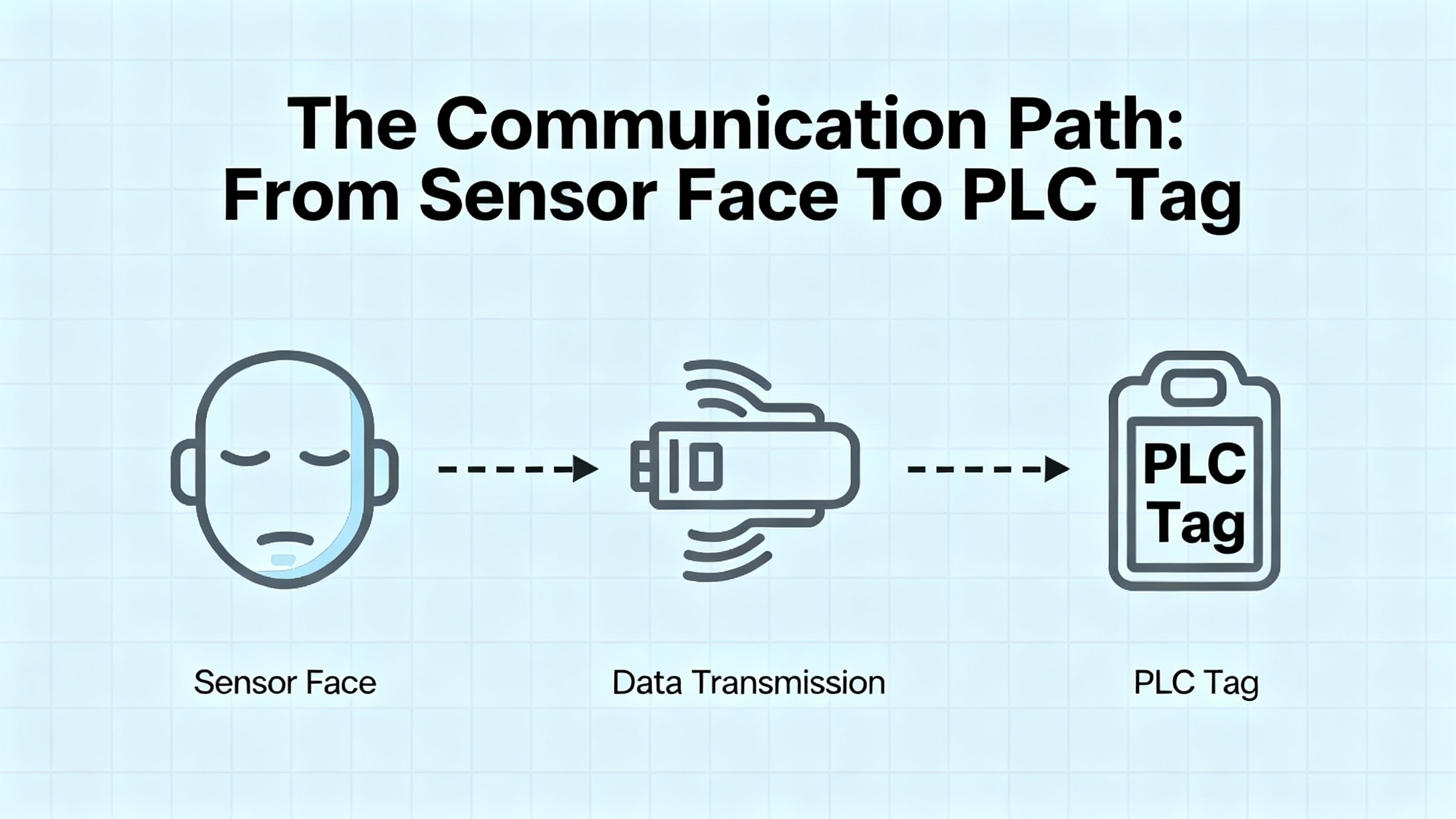
When you are standing in front of a stalled machine, it helps to mentally walk the complete communication chain:
A sensing element (inductive, capacitive, magnetic, or specialized) detects a physical change. Pepperl+Fuchs knowledge bases highlight the advantages of these electronic sensors over mechanical limit switches: noncontact detection, fast signal processing, no contact bounce, and high switching frequencies.
The sensor electronics turn that change into an electrical signal, often a clean digital switching output or an analog process value.
That signal travels over a cable or wireless link to an input module, IO-Link master, or fieldbus node, then through a network infrastructure to a controller.
The PLC or DCS logic interprets the value and maps it to tags used by HMIs, historians, and higher-level systems.
A fault anywhere on that path can be labeled as a “sensor communication error.” The rest of this article focuses on systematically narrowing down where that fault sits.
When I am called to a Pepperl+Fuchs communication problem in a live plant, I follow a fairly consistent workflow. It is shaped both by general ICS troubleshooting guidance from industrial service organizations and by sensor-specific advice from companies like Pepperl+Fuchs, Jewell Instruments, and Microsoft’s Defender for IoT documentation.
Before touching a panel or junction box, confirm that lockout/tagout is applied if you will open enclosures or work near live power. Several industrial troubleshooting guides put safety as the first and non-negotiable step, and that matches reality: no bit of uptime is worth a shock or a crushed hand.
Once it is safe to approach, gather information. Note the exact Pepperl+Fuchs error code text, which devices are showing it, and when it started. Ask operators whether the issue appeared after a power outage, product changeover, or software update. Record any other current alarms on drives, PLCs, or HMIs. This simple fact-finding dramatically reduces guesswork later.
Industrial control references consistently identify power supply issues as a primary root cause of faults. Begin by confirming that the Pepperl+Fuchs sensor or interface module is actually powered and within its rated voltage. Check any dedicated sensor supplies, as well as the controller’s power, and confirm that backup power systems (where present) are functioning.
You do not need to start with a multimeter inside a live cabinet if you are not qualified; visual checks of power indicators, fuses, and supply status often reveal obvious faults. If you are trained and permitted, measure the supply under load to detect sagging voltages that may trigger PSERR-type codes.
Multiple sources, including Jewell Instruments’ guidance on sensor wiring, stress that a large percentage of “bad sensor” complaints come down to wiring errors or degraded connections, not the sensor itself. Pepperl+Fuchs sensors are no exception.
Visually inspect the complete path from the sensor head to the next active device. Look for loose terminal screws, bent pins in connectors, crushed cables, damaged insulation, and signs of corrosion. Pay attention to field splices and junction boxes, where frayed shields often short onto signal conductors.
Compare the wiring against the Pepperl+Fuchs documentation for that exact model. The Jewell Instruments material highlights how confusion between signal common and earth or chassis ground can create ground loops and noise; this same trap appears in many industrial sensors. Use shielded twisted pair for sensitive signals and ground the shield at only one end, as recommended by sensor wiring best practices, to avoid circulating noise currents.
Once you are confident in basic power and wiring, move along the communication path.
For discrete or analog signals going straight into a PLC input card, you can measure at the input terminals to confirm the controller is seeing a signal. Vendor-independent ICS troubleshooting guidelines recommend comparing the field reading with what the PLC reports in its diagnostics or HMI to isolate whether data is lost in the field or inside the controller.
For digital communication networks, the specifics depend on the technology.
Many industrial devices ride on CAN-based networks or use derivative protocols. An electrical engineering CAN-bus discussion highlights several fundamentals that are directly relevant when Pepperl+Fuchs equipment participates in such a network.
One key point is that a healthy CAN network produces essentially no error frames during normal operation. Error frames appearing outside startup or hot-plug events are a strong sign of hardware or configuration problems.
The same article notes that a CAN bus requires at least two active nodes. A single node on a bus, without another device to acknowledge frames, will not receive ACK bits and will eventually increment its error counters into error-passive or bus-off states. Some devices allow loopback mode for single-board testing, but in a plant network you always expect multiple participants.
Topology is also critical. The recommended layout is a single main line with a 120 ohm termination resistor at each end. This should measure around 60 ohms between CANH and CANL with the system powered down. A significantly different resistance points directly to missing, extra, or incorrect terminators. At higher bit rates, termination and reflections become more critical.
Bus and stub lengths are constrained by bit rate. At roughly 1 megabit per second, guidance is to keep the total bus length around 130 ft, while lower speeds permit longer runs. Unterminated stubs off the main trunk should generally remain under about 1 ft unless carefully engineered into the timing.
Grounding and isolation matter greatly. All nodes need a common reference ground, and the article recommends running a dedicated signal ground alongside the CAN pair, rather than relying solely on noisy power returns. Large ground potential differences between nodes can exceed typical transceiver tolerances of around plus or minus 40 volts, causing failures. In such mixed-ground scenarios, galvanic isolation with its own isolated supply is a common solution.
Timing and load are the final two pillars. All nodes must share the same nominal baudrate and have sufficiently accurate clocks. CAN 2.0B allows about 1.58 percent timing error per node, with a practical recommendation of under 1 percent; crystals are preferred over RC oscillators at speeds of 250 kilobits per second and above. The bit timing configuration should place the sample point near about 87.5 percent of the bit time; poor choices here can render standard baudrates unreliable.
Bus load should ideally stay under about fifty percent utilization. At or near full load, low-priority identifiers can starve and never win arbitration, causing application-level failures even if electrical errors are rare. That kind of hidden congestion aligns closely with Pepperl+Fuchs “network congestion” communication codes.
When I am chasing a CEERR-style error on a CAN-connected device, I often work through a checklist that mirrors these points: confirm at least two active nodes, verify baudrate and bit timing, measure about 60 ohms across the bus, inspect grounding and isolation, ensure bus and stub lengths are within reasonable limits, and confirm the network is not oversubscribed.
Pepperl+Fuchs is an active supporter of IO-Link, the IEC 61131-9 standardized point-to-point communication system. A company article on IO-Link maintenance and diagnostics emphasizes how useful IO-Link is when you are trying to understand intermittent communication issues.
IO-Link devices exchange both cyclic process data and acyclic service or diagnostic data over the same three-wire cable. They can expose identification details such as type, serial number, and firmware version, along with operating hours and detailed event codes. Many problems that once required a technician in front of the machine can now be diagnosed from an engineering workstation or even an asset management system.
IO-Link masters typically store parameter sets and can automatically download them to replacement devices. This means that when you swap a Pepperl+Fuchs IO-Link sensor, you are not typing distances or thresholds by hand; the system re-parameterizes the new device. That greatly reduces configuration mismatches, a common contributor to “device incompatibility” communication faults.
Diagnostic events on IO-Link devices often include specific reasons such as cable break, short circuit, overtemperature, contamination, or degraded signal quality. When Pepperl+Fuchs communication codes point to interference or signal loss, cross-referencing the IO-Link diagnostics can tell you whether the problem looks like cabling, contamination on the sensing face, or environmental overload rather than a protocol-level failure.
Not every Pepperl+Fuchs sensor connects directly to a PLC by wire. Many plants embed them inside larger wireless architectures. Troubleshooting case studies from vendors of wireless motion and environmental sensors illustrate common communication pitfalls that apply whenever data must hop through a gateway.
One recurring theme in those studies is the need to distinguish gateway issues from individual sensor problems. When all sensors behind a given gateway go offline, experience and documentation agree that the gateway path is the prime suspect. When only one or two nodes misbehave, their local environment, wiring, or power is more likely at fault.
Range and obstacles are another universal issue. A real-world example in a smart home context showed that simply moving a sensor closer to its bridge, within roughly 15 ft, immediately restored operation. Buildings full of metal structures, dense walls, or enclosures behave the same way. In industrial settings, wireless troubleshooting recommendations consistently call for moving sensors and gateways to reduce obstacles like dense shelving, fire doors, or large appliances.
Temperature and humidity limits matter as well. A motion sensor support article, for instance, cites operating ranges of about 32 to 120°F and non-condensing humidity below ninety percent. Running devices outside such ranges can permanently damage them and lead to “offline” conditions that look like communication errors but are fundamentally environmental.
Battery condition and orientation are third-party wireless vendors’ favorite culprits. Their guidance emphasizes checking for regular status LEDs, examining data graphs for increasing gaps between readings, and confirming that high-quality batteries with correct voltage and polarity are installed. While Pepperl+Fuchs sensors themselves may be line-powered, any wireless bridges, access points, or associated devices follow the same physics. An underpowered radio path will manifest as erratic Pepperl+Fuchs communication in your control system.
The consistent pattern across these wireless case studies is simple: verify gateway health, range and obstacles, environment limits, and power before blaming the sensor or controller.

Expert sensor wiring notes from Jewell Instruments underline how often wiring and grounding drive problems that get labeled as “communication errors.”
The guidance begins with documentation: wiring varies enough by product and model that you cannot assume color codes or pinouts, and the distinction between electrical common and earth or chassis ground is critical. Some sensors require dual supplies with tied commons; miswiring these connections can create significant ground-related problems.
Good engineering practice calls for shielded twisted pair cabling, grounding the shield at only one end, keeping cable runs as short as practical, and avoiding shared grounds between unrelated circuits. Certain sensors include built-in transient protection that shunts high-voltage spikes to the case; in those designs, earth-grounding the shield at one end enhances both surge protection and noise reduction. For others without suppression, the combination of clean, regulated power and strictly proper connections is the only defense against surges.
The same guidance reminds us that environmental mechanical effects such as floor vibration, nearby heavy equipment, or even people walking near the installation can produce output variations that resemble electrical noise. Adding appropriate low-pass filtering or choosing sensors with bandwidth matched to the application can help, but without correct wiring and grounding, communication quality will always be fragile.
When Pepperl+Fuchs error codes speak of communication interference or data misinterpretation, you should picture this entire ecosystem: cable type, shield terminations, ground references, physical routing near noisy conductors, and the mechanical environment around the sensor.

Some modern industrial sensors, including network monitoring appliances, report health and data to cloud platforms. Microsoft’s documentation for troubleshooting such sensors makes several points that generalize well when a Pepperl+Fuchs device or its host controller sends data through firewalls and proxies.
The first is that cloud-connectivity troubleshooting should be done from the device’s own tools wherever possible. Health or connectivity panes often summarize whether the sensor can reach required endpoints. When it cannot, the diagnostic views categorize issues such as certificate validation errors, unreachable endpoints, DNS failures, proxy authentication problems, name resolution failures, unreachable proxies, or time drift between device and cloud.
Recommended mitigations fall into familiar networking tasks. You may need to import or trust the correct certificate authority if SSL inspection is present. You must ensure that required endpoints are allowed through firewalls and that the sensor can reach its configured DNS servers. You may have to supply the right proxy credentials or fix the proxy’s reachability. Finally, you may need to configure an NTP server so that the sensor’s clock is synchronized; significant time difference can break secure connections.
If you see Pepperl+Fuchs-related data disappear from a cloud dashboard while local HMIs still show live information, those same categories are exactly where I would start: certificates and SSL inspection, DNS and firewall rules, proxy configuration, and NTP.

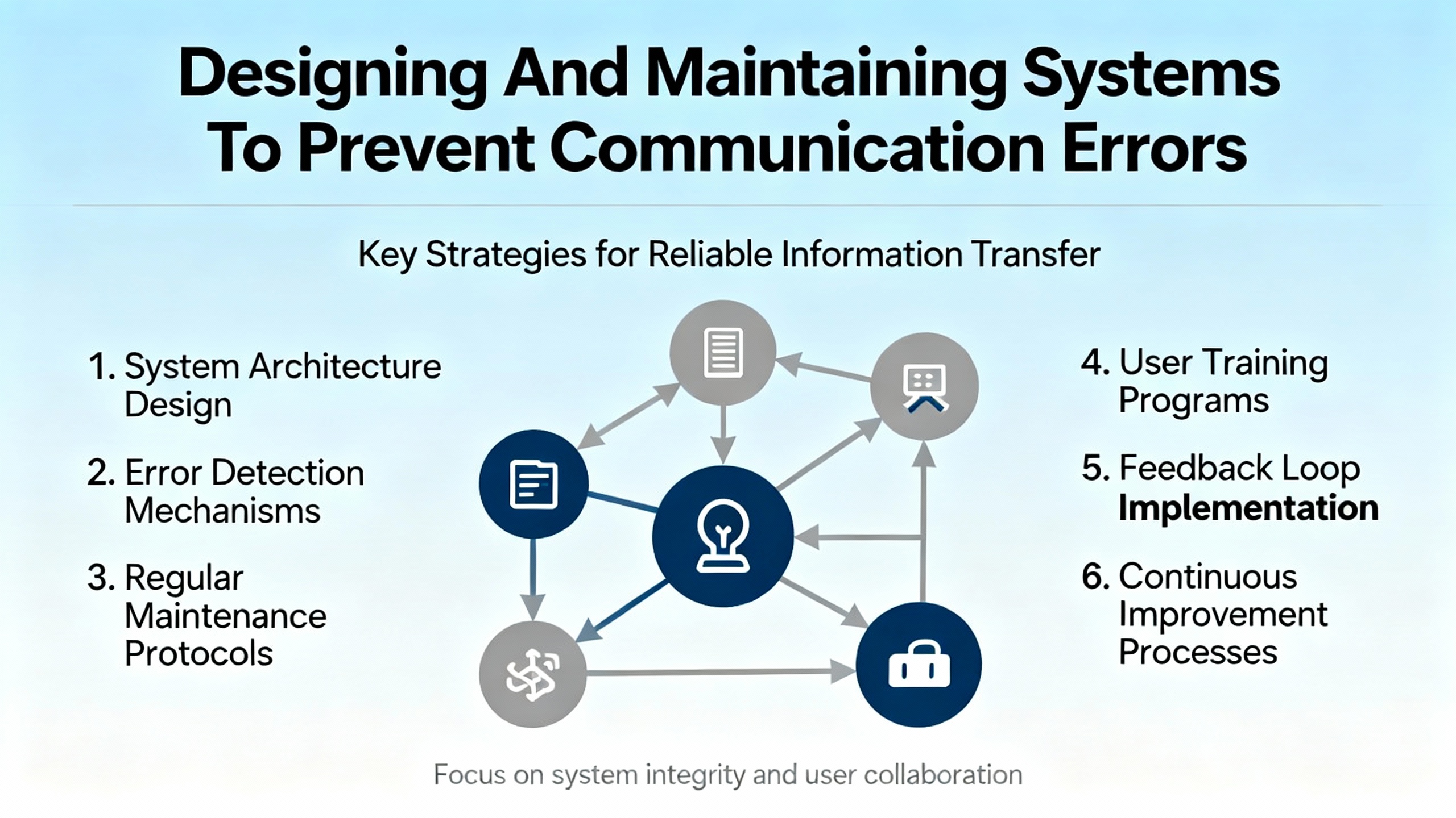
Solving today’s communication error is only half the job. The other half is reducing the odds that you will be back at the same panel next month. Reliability-oriented articles on industrial control systems, Pepperl+Fuchs knowledge bases, and IO-Link diagnostics highlight several preventive strategies.
One is choosing the right sensing technology. Pepperl+Fuchs comparisons between inductive or capacitive sensors and mechanical switches emphasize noncontact detection, fast response, resistance to contamination, and wear-free operation. In my experience, replacing mechanical limit switches in dirty or high-cycle environments with electronic sensors dramatically reduces both mechanical failures and the number of ambiguous “is it the switch or the network?” problems.
A second is embracing smart diagnostics. IO-Link devices, as described earlier, expose identification, parameter, and diagnostic data directly to PLCs, SCADA, and even cloud systems. Capturing and trending that information enables condition-based and predictive maintenance. You can see drift, contamination, or signal quality issues building long before they cause outright communication failures.
Third, treat software and configuration as assets. Neutral ICS troubleshooting sources recommend keeping controller software and device firmware up to date and performing regular backups of configurations. For Pepperl+Fuchs devices, that includes retaining parameter sets for IO-Link devices and configuration records for fieldbus modules. When a module fails, you can load a known-good configuration rather than rebuild communications from memory, reducing the risk of mismatched baudrates, IDs, or addresses.
Finally, train operators and maintenance staff on what error codes mean and what information to capture before power-cycling equipment. When people note the exact error code, the context in which it occurred, and any recent changes, remote support from Pepperl+Fuchs or your automation partner can often identify the cause faster and with fewer blind test steps.
The following concise table summarizes commonly cited Pepperl+Fuchs error codes and their high-level meanings, as described in Eltra Trade’s treatment of Pepperl Fuchs error codes and related explanatory material.
| Error code | Category | Description (per vendor-oriented sources) |
|---|---|---|
| SFERR001 | Sensor | Sensor data misinterpretation |
| SFERR002 | Sensor | Sensor malfunction |
| SFERR003 | Sensor | Discrepancies or inconsistencies in sensor readings |
| CEERR001 | Communication | Communication interference and signal loss |
| CEERR002 | Communication | Network congestion |
| CEERR003 | Communication | Device incompatibility within the communication network |
| PSERR001 | Power supply | Voltage fluctuations |
| PSERR002 | Power supply | Power interruptions |
| PSERR003 | Power supply | Power surges |
In practice, you often see multiple codes together. For example, a power sag might trigger both PSERR and CEERR events. That is why a holistic approach, combining power, wiring, and communication diagnostics, is so effective.

Q: How can I tell if a Pepperl+Fuchs “communication” error is really a bad sensor?
If the device reports sensor-focused codes like sensor data misinterpretation or discrepancies in readings alongside communication codes, and if you see implausible values or drift even when the network appears stable, a sensor issue is likely. Cross-checking with other sensors, reviewing calibration history, and, where possible, swapping in a known-good Pepperl+Fuchs device on the same cable are practical ways to separate sensor faults from pure communication problems.
Q: When should I suspect the fieldbus rather than the individual device?
When multiple nodes on the same segment exhibit intermittent faults, or when you see generic network congestion or interference errors across several devices, you should evaluate the shared infrastructure. On CAN-based networks, that means checking for correct termination (about 60 ohms between bus lines when unpowered), bus length and stub length limits, grounding strategy, and baudrate configuration. On IO-Link or Ethernet-based systems, focus more on switch ports, cabling, and higher-level network load.
Q: When is it time to involve Pepperl+Fuchs or a specialist integrator?
If you have verified power, wiring, and basic network health, and the same error recurs on replacement hardware, or if IO-Link and controller diagnostics point to internal device or protocol-level problems that are not explained in the available manuals, it is prudent to involve Pepperl+Fuchs technical support or a qualified industrial automation firm. Prepare by gathering error codes, timestamps, topology diagrams, firmware versions, and a list of troubleshooting steps already performed; several industrial support organizations explicitly cite this as the information that speeds up correct diagnosis.
Bringing a Pepperl+Fuchs sensor back onto the network is rarely magic. It is usually the result of disciplined wiring practices, sound fieldbus design, and a habit of reading and acting on the diagnostics these devices already provide. Approach communication errors methodically, respect the basics of power and grounding, and make smart use of IO-Link or fieldbus tools, and you will see far fewer “silent” sensors and much more stable automation.


Copyright Notice © 2026 mooreautomated.com All rights reserved,Moore Automated is not an authorized distributor or representative of the manufacturers featured on this website. Brand names and trademarks featured are the property of their respective owners.


Leave Your Comment