


MP 3009X
Get A Quote
When a production line stops because ŌĆ£a Turck sensor went bad,ŌĆØ everyone on the floor feels the pressure. In practice, I find the actual root cause is often wiring, environment, or process issues rather than the sensor hardware itself. In process industries and factory automation, research on fault diagnosis shows that sensor failures are among the most common equipment problems and that distinguishing a real sensor fault from a process fault is one of the hardest tasks for operators and engineers. Getting that distinction wrong wastes money, parts, and credibility.
This article walks through a practical, field-tested approach to diagnosing malfunctions on Turck sensors and similar industrial devices in PLCŌĆæbased automation. The focus is on how you work through a problem safely, methodically, and fast enough to matter on a live line.
Sensors are the way your PLC, DCS, or safety controller perceives the real world. As AutomationDirect has pointed out, they are the eyes and ears of automation, providing information about object presence, position, level, distance, and process conditions so that control logic can act correctly. An automation guide from Arce Otomasyon describes a sensor as a device that detects a physical variable such as temperature, pressure, light, speed, or position and converts it into an electrical signal that the control system can process.
In most industrial plants, Turck sensors sit in this role on conveyors, packaging machines, robot cells, and process skids. Typical categories include nonŌĆæcontact proximity sensors, photoelectric sensors, pressure and level transmitters, temperature sensors, and motion or position encoders.
They do far more than just start and stop actuators. They enable:
RealŌĆætime feedback control, such as stopping a conveyor when a product arrives or maintaining a tank within a pressure or level band.
Quality control, by verifying the presence, orientation, or size of parts before expensive downstream steps.
Predictive maintenance, when their data is trended to catch anomalies before they turn into breakdowns.
Safety, by providing presence detection, interlock feedback, and emergency trip inputs.
Because so many other devices depend on their readings, a malfunctioning sensor can masquerade as a faulty valve, motor, or even PLC program. That is why a disciplined diagnostic mindset is essential.

Fault diagnosis literature makes a useful distinction between three terms. A fault is any problem, including nonŌĆæoptimal operation or offŌĆæspec product. A symptom is an observed event or value that tells you something is wrong, such as an input never changing state or a pressure reading that jumps randomly. A root cause fault is the underlying problem that drives the other symptoms and that you must correct to permanently fix the issue.
In industrial automation, fault detection is recognizing that something is wrong, often through alarms, interlocks, or trend deviations. Fault diagnosis is going a step deeper and pinpointing the root cause enough to choose and implement corrective actions.
When you hear ŌĆ£the Turck sensor failed,ŌĆØ that is usually just a hypothesis about the root cause. The symptom may be a cylinder that will not extend, an HMI alarm about a level too low, or an intermittent jam in a packer. The job is to determine whether the fault lies in the sensor, the wiring and interface, the control logic, or the process and mechanics around it.
Research on complex operations shows that assuming a single fault is often wrong; multiple issues can coexist. A sensor might drift slightly while a valve is sticking and an alarm threshold is poorly tuned. A good diagnostic strategy therefore combines structured methods with onŌĆætheŌĆæground judgment.
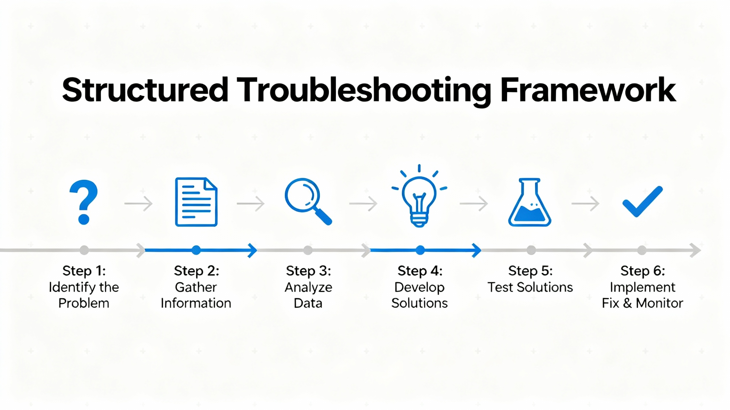
Experienced troubleshooters do not rely on guesswork. A wellŌĆæknown Navy sixŌĆæstep procedure, referenced in DigikeyŌĆÖs troubleshooting guide, starts with symptom recognition and elaboration, then moves through listing probable faulty functions, localizing the faulty function, localizing trouble to the circuit, and finally failure analysis and documentation. Control Engineering has similarly described seven fundamentals that begin with simple checks and progress toward deeper analysis and root cause work.
Industrial automation training material from OJ Automation frames troubleshooting as a stepŌĆæbyŌĆæstep rootŌĆæcause analysis: define the problem clearly, check external factors, analyze alarms and error codes, isolate the faulty component, perform componentŌĆæspecific checks, implement the fix, then document and prevent recurrence.
Those frameworks all boil down to the same mindset. Understand what ŌĆ£normalŌĆØ looks like for that machine. Capture the symptoms precisely. Start with the basicsŌĆöpower, wiring, environment, configurationŌĆöbefore you blame advanced hardware or software. Only then swap parts or rewrite logic.
That mindset applies directly to Turck sensor diagnosis.
Before touching any sensor or opening panels, you need a safety plan. The troubleshooting guide from Digikey emphasizes that safety is not optional: follow lockout/tagout for electrical, pneumatic, and hydraulic energy; comply with OSHA and plant standards; use appropriate PPE; remove conductive jewelry; secure hair and clothing; and never delegate responsibility for your own safety.
Be especially cautious in service panels or cabinets where interlocks may be bypassed during testing. Lethal voltages can be present even when the machine looks idle. For pneumatics or hydraulics, do not use your hands to feel for leaks, as noted in the same guide; highŌĆæpressure fluid injection injuries are catastrophic.
On many of my calls, it is clear that technicians could have saved time and risk by spending a minute on a proper lockout, verifying absence of voltage, and planning the test steps before diving in.

The first step is to convert ŌĆ£it is not workingŌĆØ into a precise description of what the system is doing and when. Both DigikeyŌĆÖs framework and OJ AutomationŌĆÖs guidance stress symptom recognition and elaboration as the foundation of good troubleshooting.
On a Turck sensor job, that often means asking the operator and watching a full cycle. You want to know whether the sensor never changes state, changes at the wrong time, jitters intermittently, or apparently behaves normally while the process still produces bad product.
Run the machine up to the failure point. Does the HMI show an alarm tied to that sensor tag? Does the PLC diagnostics page indicate an input fault? Are there nuisance alarms involving this point, suggesting borderline behavior rather than a hard failure?
Make notes on the conditions: line speed, product type, environmental conditions such as high humidity or heat, and any recent changes in the area. Maintenance logs and service records, as recommended in DigikeyŌĆÖs and LinkedInŌĆÖs documentation advice, are particularly valuable for intermittent or temperatureŌĆædependent faults.
You should come out of this phase with a concise statement such as ŌĆ£the infeed Turck photoeye fails to detect short cartons on Line 2 when speed exceeds a certain rate, resulting in missed picksŌĆØ rather than ŌĆ£the photoeye is bad.ŌĆØ
A key insight from fault diagnosis research is that many apparent instrument faults are actually process faults in disguise. Greg StanleyŌĆÖs work on abnormal condition management in process plants notes that sensor failures are common, but distinguishing sensor problems from true process problems is a major practical challenge.
A few reality checks can prevent you from replacing a good sensor:
Ask whether the process behavior matches the reading. If a level sensor claims a tank is empty but the sight glass or manual dip shows fluid present, suspect the sensor chain. If a position sensor does not change state but the part never physically arrives due to a jam upstream, the issue is mechanical.
Compare with independent information. Some systems have redundant sensors, such as two pressure transmitters on a safetyŌĆæcritical loop. Other times you can crossŌĆæcheck with a different variable, such as flow or motor current versus a flow or position sensor.
Consider recent changes. Setpoint drift, as highlighted in building automation and BAS maintenance literature, can mask underlying issues. A software offset added ŌĆ£temporarilyŌĆØ for a drifting sensor can make it look normal while hiding an underlying mechanical or wiring problem.
Avoid jumping directly to part replacement. As MidAtlantic Controls points out, quick software offsets or superficial fixes can hide the true root cause and lead to repeated service calls and energy waste.
If after this analysis the symptoms still line up with a measurement problem rather than a simple mechanical or process issue, it is time to go to the field device.
Most sensor issues reveal themselves quickly once you stand in front of the device. Control EngineeringŌĆÖs troubleshooting fundamentals emphasize using your senses, along with simple tools, to look for anything out of the ordinary.
Start with a visual inspection. Look for cracked housings, damaged cables, missing mounting hardware, loose brackets, misaligned targets, or signs of impact. WFsensorsŌĆÖ guide on common sensor troubleshooting stresses that mechanical damage, poor mounting, and vibration can cause stability problems, reduced accuracy, and intermittent operation.
Check the sensing face and surrounding area for contamination. Dust, powder, grease, oil, and product buildup can block or distort the field of photoelectric and capacitive sensors. Monolithic PowerŌĆÖs discussion of deployment challenges notes that dust and debris are especially troublesome for optical and capacitive devices, and that enclosures or shields may be needed in harsh environments.
Inspect connectors and junction boxes. The heavyŌĆævehicle sensor article summarized in the research notes boils the first steps down to inspecting the sensor, checking wiring and connections, and looking for damage. Loose connectors, pulledŌĆæout conductors, and pinched cables are routine causes of intermittent faults.
Listen, smell, and feel carefully. Unusual buzzing or clicking near the sensor cable, burnt odor, or local hot spots may point to shorts or overloaded electronics. As Control Engineering notes, touch is useful for sensing heat or abnormal vibration, but use it carefully and only on deŌĆæenergized or lowŌĆærisk areas.
If you spot an obvious external fault such as a cut cable or misaligned bracket, correct it, then retest the machine through its normal operation. Many ŌĆ£sensor failuresŌĆØ are resolved at this stage without touching the sensor hardware.

When the mechanical side looks reasonable, shift to the electrical chain that runs from the power supply through the sensor and into the PLC or safety controller. WFsensors and CappUSA both stress that troubleshooting almost always begins with power, wiring, and configuration.
Confirm that the sensor is being supplied with the correct voltage and polarity, and that its ground or reference is solid. WFsensors recommends comparing the actual voltage with the sensorŌĆÖs nameplate or datasheet requirements and ensuring that the supply is stable and within range.
Measure:
The supply voltage at the sensor connector under load.
Continuity of the ground or common return path back to the cabinet.
Any unusual voltage drops along the cable if it is long or routed through multiple junctions.
If the measured power is outside the specified range, or if there is sporadic loss of power due to loose terminals, the sensor output will be unreliable no matter how good the hardware is.
Next, verify that the sensor output behaves as expected when you stimulate it. WFsensors outlines several diagnostic methods that apply directly here: visual inspection of indicators, multimeter signal checks, and, where appropriate, oscilloscope waveform analysis.
Use the sensorŌĆÖs own indicator LED if it has one. Actuate the target (approach metal to an inductive sensor, block the beam on a photoelectric sensor, apply pressure or move the mechanical element) and watch whether the LED switches reliably at a stable point.
Measure the output at the sensor terminals. If the sensor has clean power but the output voltage or current never changes when you actuate it, the device is likely faulty or misŌĆæconfigured.
Compare readings at the PLC input terminals. If the signal is correct at the sensor but absent or distorted at the PLC, the fault lies in the cable, connector blocks, or input module, not in the Turck device.
If the process is fast or dynamic, a scope is helpful for checking for noise, oscillations, or missing pulses. WFsensors notes that waveform analysis can reveal distortion, frequency, and amplitude anomalies that a simple meter cannot show.
PLC and HMI diagnostics are valuable but must be interpreted carefully. The Digikey troubleshooting guide points out that I/O channel LEDs are very useful for slow, discrete signals like limit switches and solenoids, but are unreliable indicators for fast pulses and highŌĆæspeed counting. PLC status pages, error logs, and HMI alarms help you see whether the controller is at least seeing transitions at the point of failure.
OJ Automation emphasizes reviewing PLC and SCADA alarms and error codes, consulting vendor manuals to interpret recurring codes, and verifying that I/O mappings and configuration match the physical wiring. A sensor wired into the wrong terminal or mapped to the wrong tag can behave ŌĆ£incorrectlyŌĆØ even though both the device and the PLC input are functioning.
At this stage, you should know whether the sensor is correctly powered, whether its own output is switching properly, and whether the PLC sees that change consistently. Only when all three conditions are not met do you have strong evidence of a Turck sensor malfunction.
In practice, most sensor problems fall into recognizable patterns. Based on the failure modes described in WFsensors, StroboxŌĆÖs article on sensor failure, and automation field experience, you can relate typical symptoms to likely fault areas as shown below.
| Field symptom | Likely fault area | Practical check |
|---|---|---|
| Sensor never switches, indicator LED off | Power supply, wiring, connector | Measure supply at sensor, inspect wiring and terminals, verify correct voltage |
| Sensor LED works, but PLC input never changes | Field wiring, terminal block, input module | Compare signal at sensor and at PLC, inspect connectors and cable routes |
| Sensor appears always on, regardless of target or condition | Misalignment, contamination, configuration | Clean sensing face, realign, verify mounting distance and sensor settings |
| Sensor output is noisy or unstable, causing nuisance trips | EMI, loose wiring, vibration, environment | Check grounding, cable routing, shielding, mechanical support |
| Reading drifts over time without process changing | Zero or span drift, temperature, aging | Compare with reference, check temperature, recalibrate or replace as needed |
| Fault occurs only at high speed or under specific environmental conditions | Response time limits, process dynamics, heat | Check application limits, trend data, evaluate sensor selection and mounting |
This table is not a substitute for diagnosis, but it helps focus your attention on the most probable causes so you do not chase unlikely ones first.
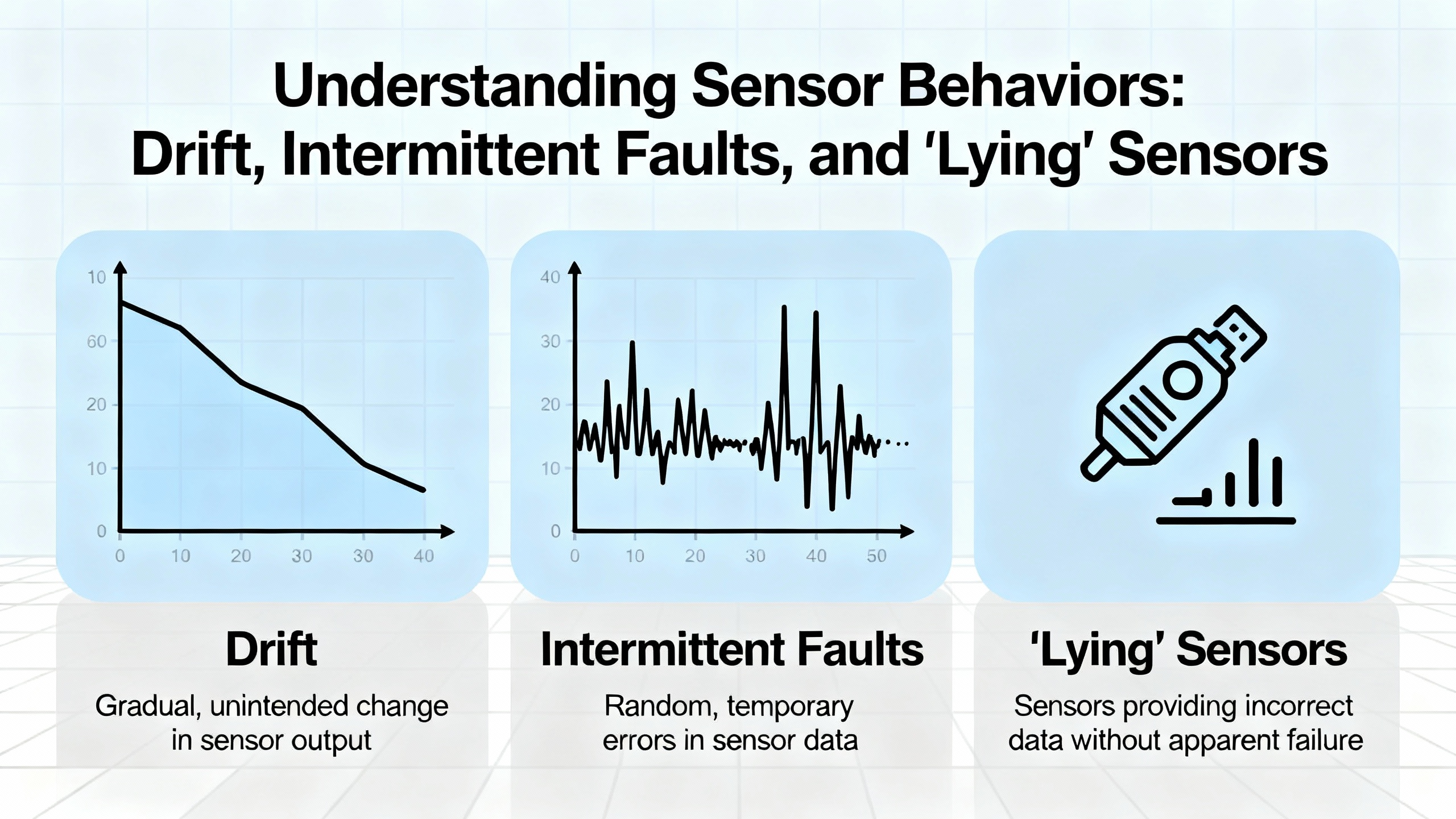
Some of the most frustrating Turck sensor calls involve intermittent faults or drift rather than clean failures. WFsensors defines zero drift as fluctuation of sensor output when no input signal is present, usually caused by temperature or humidity changes, power variation, or component aging. Span drift, described in instrumentation troubleshooting summaries, changes the slope of the measurement so that high readings are off even when low readings look correct.
MidAtlantic Controls notes that in building automation, setpoint drift and compensation strategies can hide these issues. A software offset or filter applied to an unreliable sensor can mask the hardware problem until it becomes severe, at which point you may see erratic control, energy waste, or offŌĆæspec product.
To diagnose drift and intermittent problems:
Use trend data from the PLC, HMI, or historian. Look for slow changes in baseline, sudden jumps that correlate with environmental conditions, or repeated patterns around certain times or modes.
Log context along with the sensor values. Service logs recommended by Digikey and the LinkedIn documentation guide become crucial here; they help you see whether recurring issues align with ambient temperature swings, washdown cycles, or nearby equipment starts.
Evaluate environmental conditions versus specifications. Monolithic PowerŌĆÖs discussion of longŌĆæterm stability emphasizes that drift is affected by temperature extremes, power fluctuations, mechanical stress, and firmware or software anomalies. Sensors installed right next to hot equipment, noisy drives, or vibrating machines may be outside their intended operating envelope.
Consider substitution testing. WFsensors recommends swapping a suspect sensor with a knownŌĆægood unit after power is safely removed. If the issue disappears with the replacement and reappears when you move the suspect device to another equivalent location, that is strong evidence of a sensor hardware problem.
Be cautious with pure ŌĆ£shotgunningŌĆØ strategies where you change multiple components without analysis. Control Engineering notes that indiscriminate substitution is inefficient and can destroy new components if the underlying cause, such as overvoltage or miswiring, has not been removed.
Most sensor problems can be prevented at the design and installation stage. Monolithic PowerŌĆÖs overview of deployment challenges highlights several realŌĆæworld factors that degrade sensor performance compared with lab conditions.
Temperature extremes affect both materials and electronics. Metals expand and contract, and resistances change, potentially altering calibration and switching thresholds. Choosing components rated for the temperature range they will see and, when needed, using temperature compensation techniques reduces this risk.
Moisture is a double threat. It causes corrosion on terminals and housings and, because water conducts electricity, can create false paths and shorts. Proper ingress protection, waterproof housings, sealed connectors, desiccants, and hydrophobic coatings are common defenses for sensors exposed to washdown or high humidity.
Dust, debris, and product buildup can obscure beams and alter dielectric properties near capacitive and optical devices. Enclosures, air purges, and thoughtful placement away from heavy contamination zones are straightforward mitigations.
Vibration and mechanical stress shorten sensor life and cause intermittent readings by loosening connections. ShockŌĆæabsorbing mounts, strain relief on cables, and robust mounting brackets, as recommended in MonolithicŌĆÖs guidance, help maintain longŌĆæterm stability.
Environmental factor analysis, as described by WFsensors, should be a routine part of both diagnosis and design. Check ambient temperature, humidity, electromagnetic interference sources, and mechanical mounting conditions against the sensorŌĆÖs data and your own experience. If the installation consistently pushes a device beyond reasonable limits, redesign that part of the machine rather than repeatedly replacing sensors.
Modern sensors are becoming smarter and more connected. Arce Otomasyon notes that advances in IoT and AI are turning traditional devices into intelligent nodes that not only capture data but participate in distributed analysis and decisionŌĆæmaking. StroboxŌĆÖs article on sensor failure in automation describes a future where sensors perform selfŌĆædiagnostics and can predict their own failures.
Monolithic Power also highlights selfŌĆædiagnostic features and continuous monitoring as key elements of safety and reliability, especially in critical infrastructures. Redundant sensors, builtŌĆæin selfŌĆæchecks, and failŌĆæsafe design, where a failure drives the system to a safe state, are particularly relevant for safetyŌĆærated Turck installations.
With increased connectivity comes increased cyber risk. CTI ElectricŌĆÖs discussion of industrial automation cybersecurity points out that more networked devices and remote access points expand the digital attack surface. Misconfigured or compromised automation networks can lead to false data, unexpected commands, and hazardous conditions.
For sensor systems, that means:
Treat configuration interfaces and remote diagnostics as potential attack vectors. Limit access, secure credentials, and use segmented networks where possible.
Validate measurement plausibility. If a sensor value jumps in a way that conflicts with physical reality, consider not only hardware faults but also communication and cyber issues.
Manage firmware updates carefully. As with DCS systems, updates should be validated before deployment and scheduled in a controlled manner to avoid introducing new faults.
By combining smart sensor diagnostics with sound cybersecurity practices, you can use advanced features without trading away trustworthiness.
Even the best diagnosis loses value if the knowledge disappears after the shift. Both the Digikey guide and LinkedInŌĆÖs advice on sensor troubleshooting stress the importance of documentation.
Maintain a machineŌĆæspecific service log that records the symptoms, troubleshooting steps, repairs, and operator observations for each incident. Over time this builds a history that makes intermittent or environmental issues much easier to diagnose and keeps different technicians aligned on what has already been tried.
Physically label sensors with identifiers that match PLC tags and drawings. Include installation dates and, when relevant, calibration dates. Clear labeling saves time on every future maintenance task and reduces the chance of adjusting or replacing the wrong device.
Use structured procedures. OJ Automation and Control Engineering both recommend checklists, flowcharts, and tables of procedures, accessible at the HMI or in maintenance documentation. These prevent skipped steps under pressure and provide a starting point for training new technicians.
Implement preventive tasks focused on sensors. WFsensors and MidAtlantic Controls recommend regular inspections, cleaning, functional testing, and calibration where applicable. For critical loops, plan calibration intervals based on stability and process risk, recognizing that all sensors drift over time.
The result is fewer surprise outages, more predictable behavior, and a culture where sensor issues are addressed systematically rather than reactively.
Q: How can I quickly tell whether a Turck sensor is really faulty or if the problem is wiring or the process? In the field, the fastest reliable approach is to check three things in order. Confirm the process itself: that the target actually reaches the sensing point at the right time and is not blocked or misaligned. Verify power and wiring by measuring supply voltage at the sensor and confirming continuity of the return path. Then actuate the sensor while measuring its output at both the device and the PLC input terminals. If the process is correct and power is good, but the sensor output never changes at its terminals, the device is very likely faulty. If the output changes at the sensor but not at the PLC, the issue is wiring or the input module. If both behave correctly yet the machine still acts wrong, the fault is probably in the control logic or mechanical sequence, not in the sensor.
Q: What are the most common environmental causes of Turck sensor malfunctions in automation systems? Industry guidance on sensor deployment and troubleshooting points to temperature extremes, moisture and corrosion, dust and debris on sensing faces, mechanical vibration, and electromagnetic interference as the main environmental culprits. Excess heat or cold alters electronic behavior, moisture causes corrosion and unintended conductive paths, dust blocks optical paths, vibration loosens wiring, and EMI from drives or welders injects noise into signals. Comparing actual site conditions with the sensorŌĆÖs rated operating ranges and using enclosures, shielding, and proper mounting usually addresses these issues more effectively than repeated part replacement.
Q: When should I recalibrate a sensor versus replacing it outright? WFsensorsŌĆÖ troubleshooting guidance notes that drift over time is inevitable, and calibration compares sensor output to a known reference to bring it back within tolerance. If a sensor is stable but offset or slightly out of range, and it is installed in a reasonable environment, recalibration according to the manufacturerŌĆÖs procedure is appropriate. If it shows large or rapidly changing drift, intermittent output, physical damage, or clear sensitivity loss despite proper conditions, replacement is typically the safer and more economical choice. In safetyŌĆæcritical applications, conservative replacement policies and redundancy reduce risk further.
On a busy line, the temptation is always to declare ŌĆ£the Turck sensor is badŌĆØ and swap hardware until the alarms go away. The plants that run reliably take a different path: they treat sensors as part of a larger diagnostic system, follow a disciplined troubleshooting process, and design installations that respect environmental and maintenance realities. If you build that discipline into your daily work, you will spend less time chasing ghosts and more time keeping machines running the way they should.


Copyright Notice © 2026 mooreautomated.com All rights reserved,Moore Automated is not an authorized distributor or representative of the manufacturers featured on this website. Brand names and trademarks featured are the property of their respective owners.


Leave Your Comment