


MP 3009X
Get A Quote
When an I/O module dies in the middle of a production run, the plant does not care about elegant design. It cares about getting communication back and keeping people and equipment safe. As an industrial automation engineer who gets called when a line is down, I have learned that urgent I/O module replacement is not about heroics. It is about having a disciplined, wellŌĆærehearsed playbook that you can execute under pressure.
This article walks through that playbook, drawing on best practices from vendors such as Schneider Electric, Rockwell Automation, Siemens, Honeywell, NetApp, Trend Micro, Opto 22, Weidm├╝ller, ODVA, and others, and adapting them to the reality of PLC, HMI, and factory automation systems.
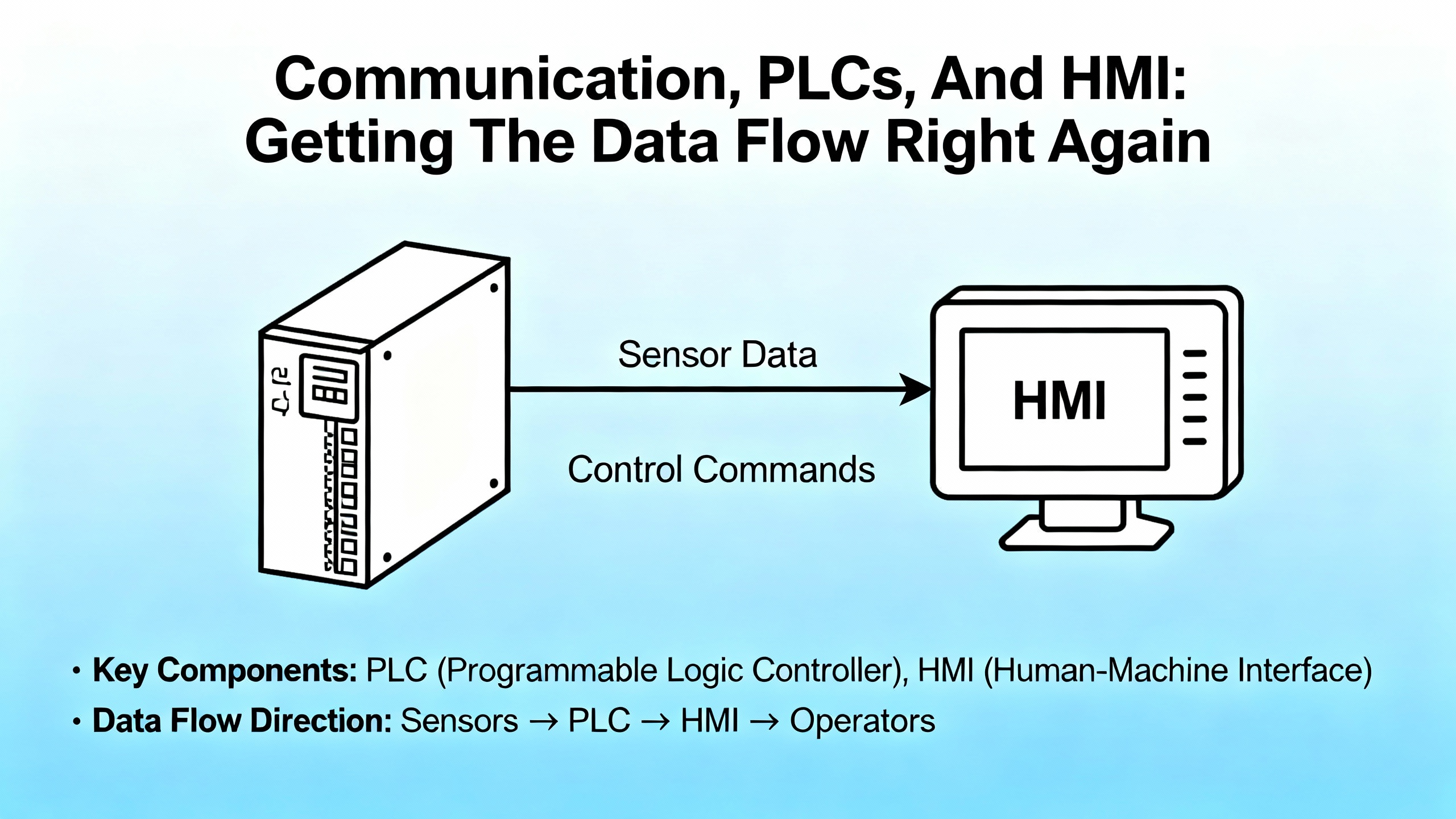
An I/O module is the hardware interface between your controller and the real world. It connects sensors, switches, and actuators to a PLC, DCS, or PAC, handling signal conditioning, isolation, and conversion so the controller can interpret field signals and drive outputs correctly. As Schneider Electric and Honeywell documentation emphasize, you typically see several families of modules: discrete input and output modules that handle on and off states; analog input and output modules that work with continuous ranges such as 4ŌĆō20 mA or 0ŌĆō10 V; and special modules for temperature, motion, safety, or communication.
Zero Instrument and Control Engineering describe the I/O layer as the place where miswired, noisy, or failed signals quickly turn into downtime and quality loss. CoreTigo points out that failures here are not abstract: short circuits and open circuits can stop production, trigger bad product, or create safety risk if critical signals are not relayed.
When a module fails, you may lose entire groups of points at once. To a PLC, that can look like input loss, output card fault, or full rack communication failure. The urgent job is to restore reliable communication between field devices and controller, not just silence alarms.
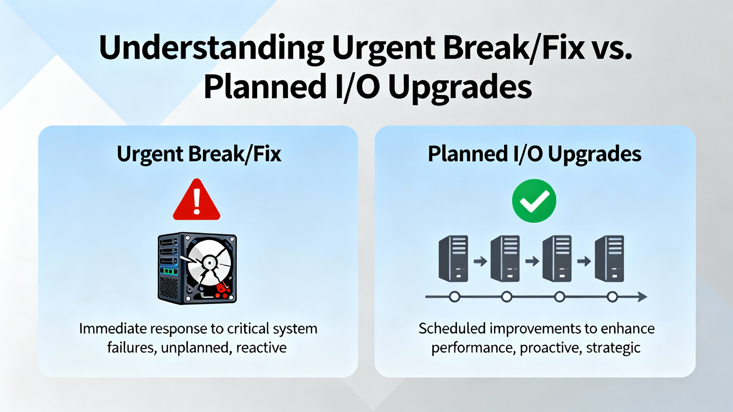
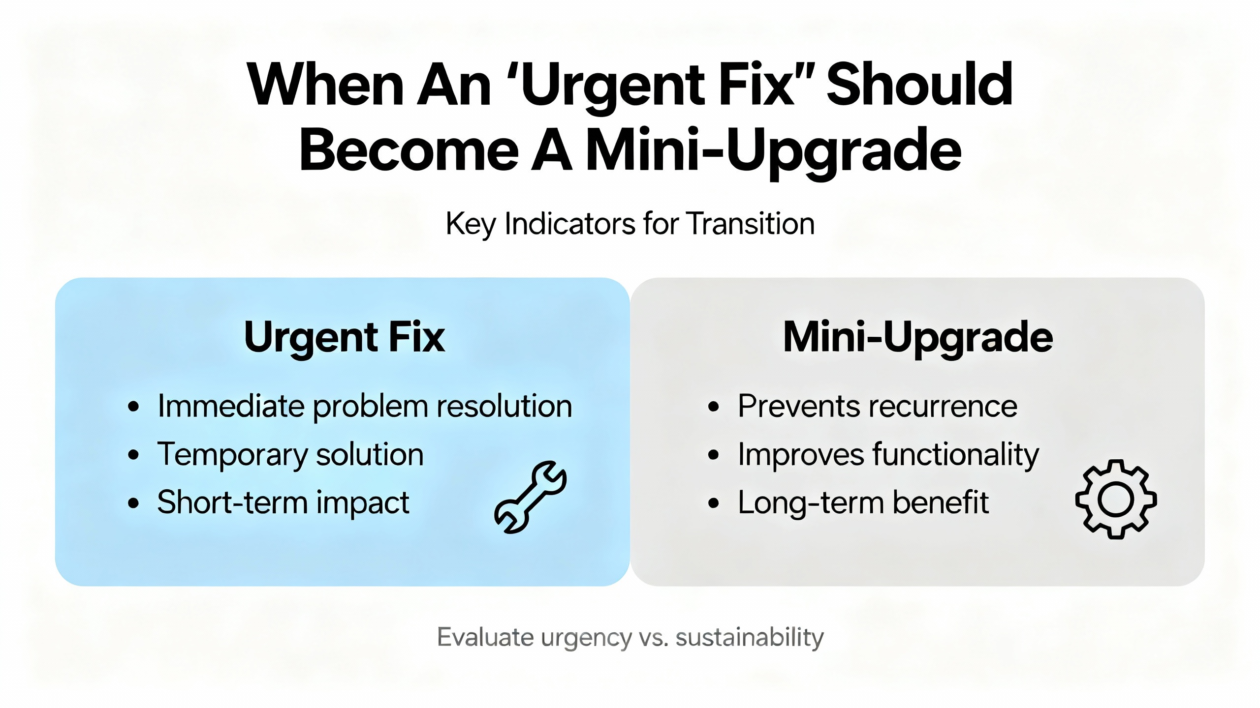
Control Engineering distinguishes between highŌĆærisk I/O upgrade projects, which should be heavily planned, and the urgent fixes you perform in a live plant. In a perfect world, every module change would be a planned upgrade during a generous shutdown window, with new rack layouts, rewired terminal strips, and maybe even new processors or networks.
Reality often looks different. A water plant or power utility may run 24/7, with no luxury of long downtime. A packaging line may have a tight shipping window and every minute of downtime has a dollar figure attached. So you often have to blend the mindset of a planned upgrade with the constraints of an urgent repair.
In an urgent I/O module replacement service, the priorities are clear. First, keep people and equipment safe. Second, protect the process from bad transitions and unintended actuation. Third, restore communication quickly and correctly, not just ŌĆ£good enough to clear the fault.ŌĆØ Finally, capture enough information to plan a more thorough upgrade later if the failure is a symptom of a bigger problem.
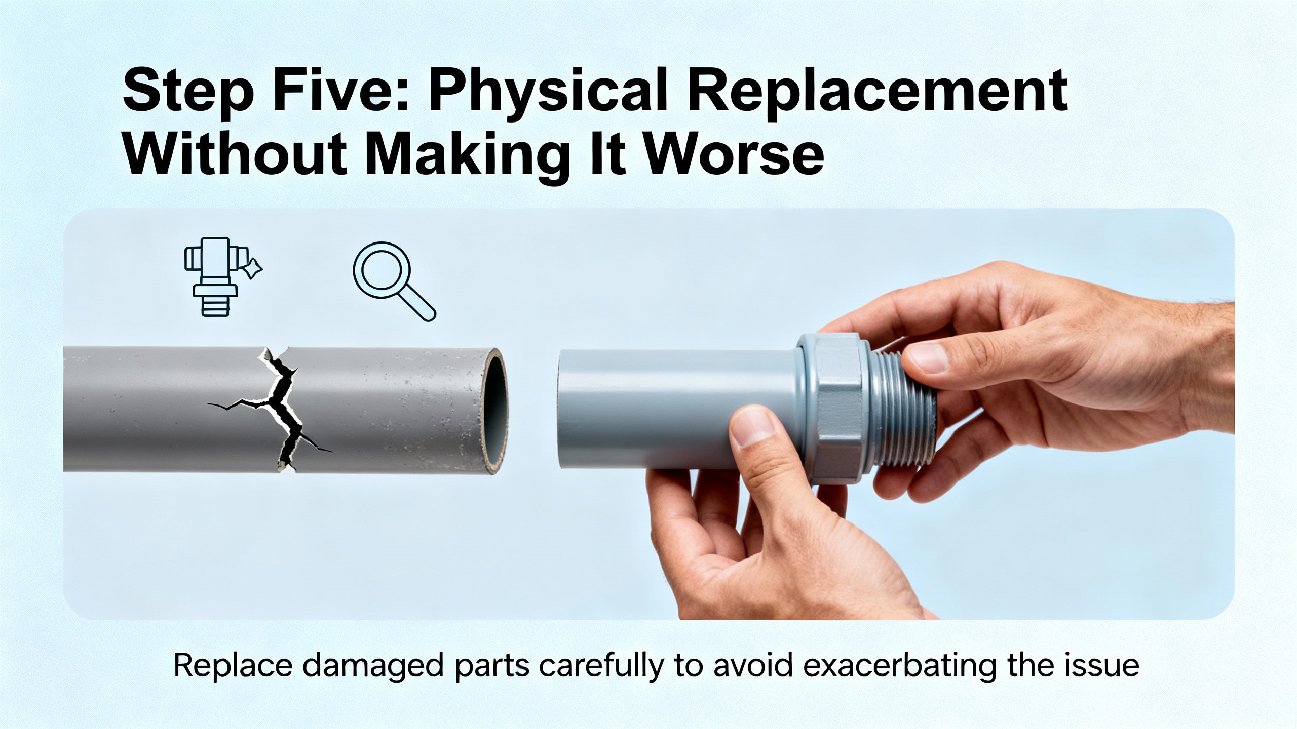
The easiest way to create a bigger outage is to pull an I/O module while the process is still in an unstable state. Schneider Electric guidance for building automation systems is clear: before removing a module, place affected equipment into a safe state. That may mean commanding outputs off, driving valves closed, putting VFDs in local manual, or switching a loop into a proven fallback mode.
Siemens documentation for SIMATIC ET 200SP adds nuance with the idea of substitute value behavior. For each output slot, the controller can be configured to either hold the last value, switch to a predefined safe value, or go currentŌĆæfree and deŌĆæenergized when control is not available. During faults, CPU stop, communication interruptions, or firmware updates, the module automatically enforces this substitute behavior. In practice, that means if you disconnect a distributed I/O station without planning, you may suddenly freeze outputs or drop them to safe state depending on configuration.
When I am on site, I treat this first step as three quick questions that I answer before I even pick up a screwdriver. I ask whether the process is currently in a stable operating point and whether I fully understand what will happen to each affected actuator if the controller stops driving it. Then I consider whether I can put that part of the process into a planned safe condition, such as clearing product from a conveyor or isolating a section of piping.
Taking a few minutes to align safe states with substitute value behavior and bypass conditions avoids surprises later in the job.
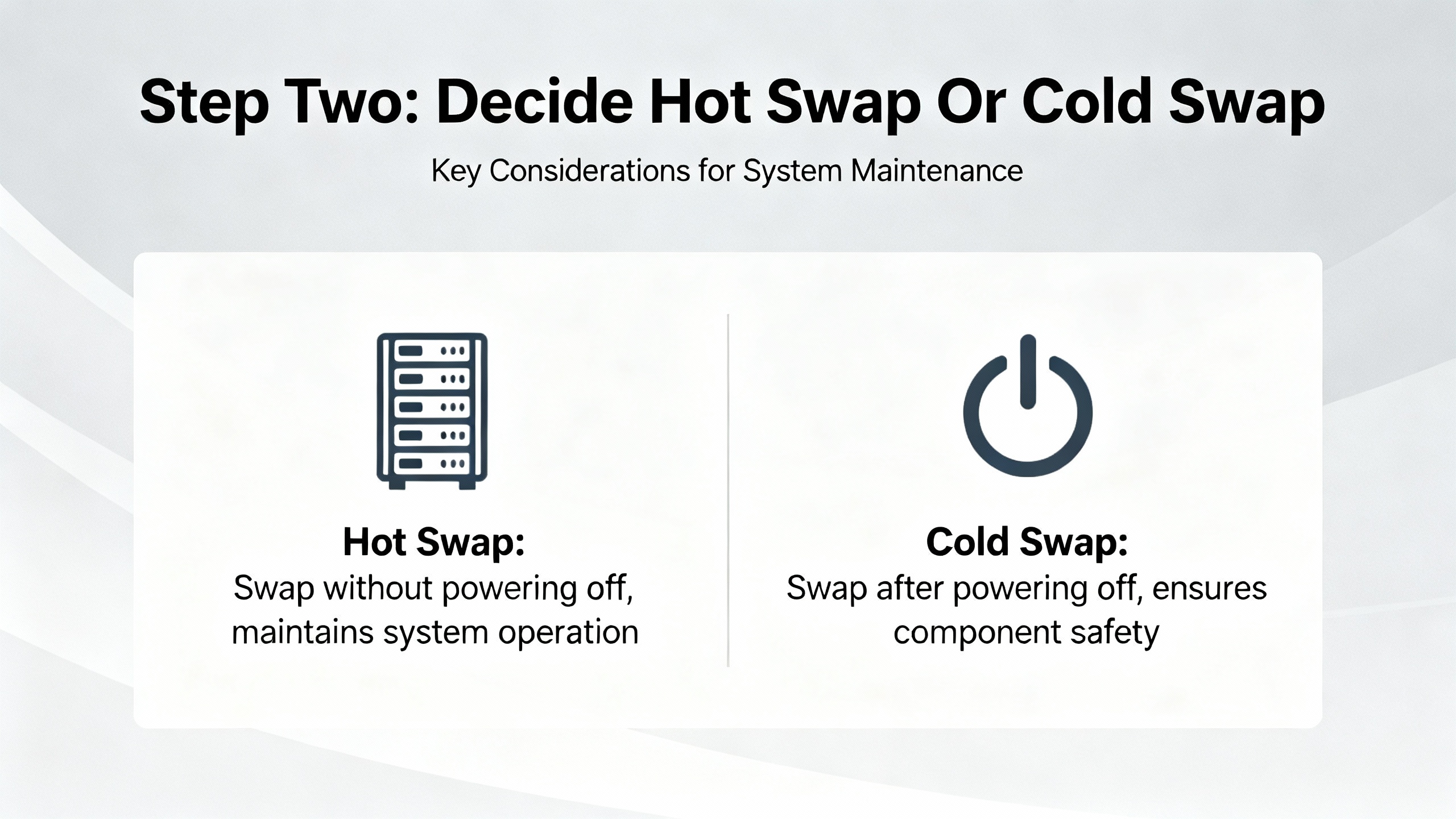
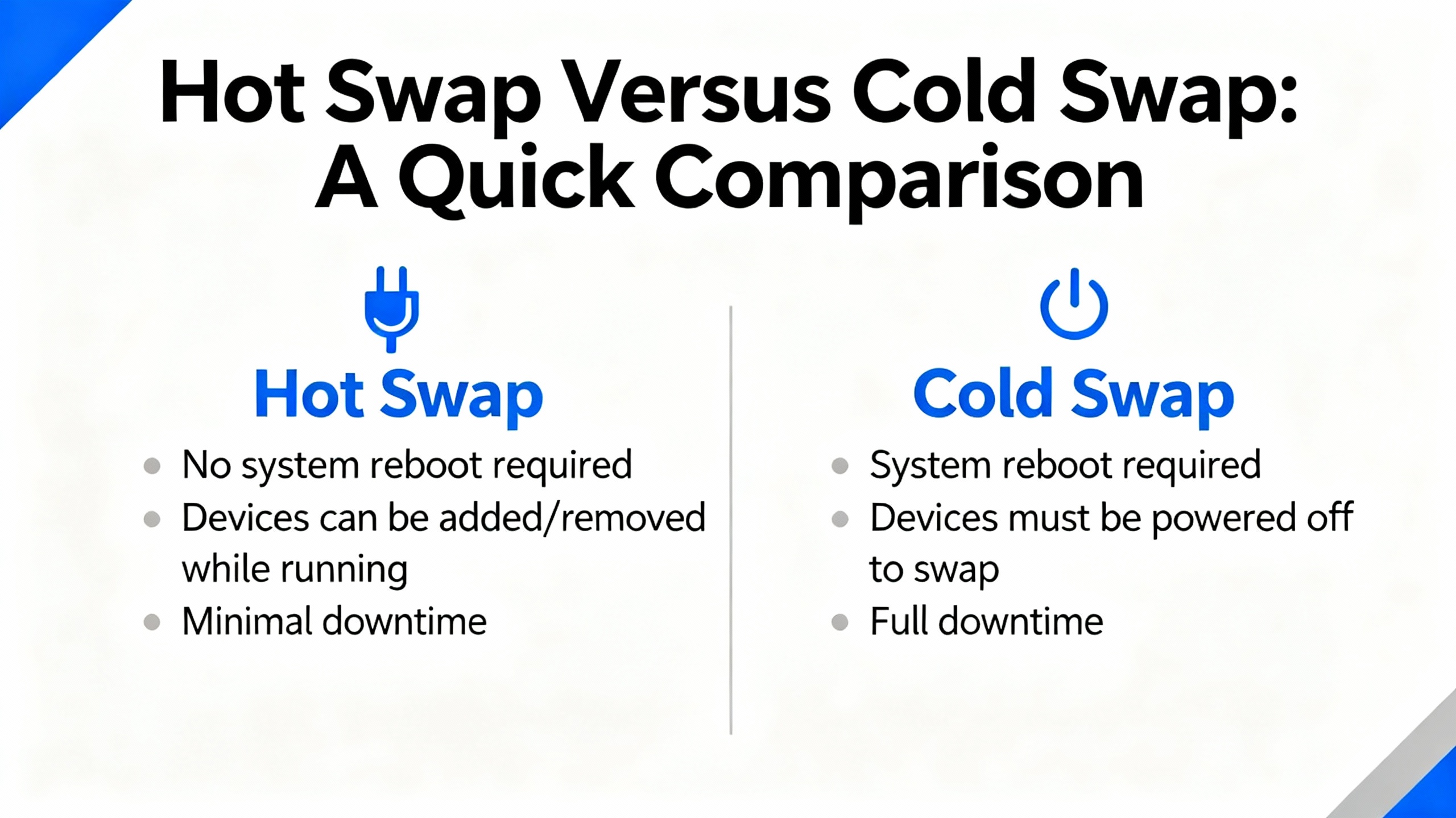
The next decision is whether you are going to hotŌĆæswap the I/O module with power on or perform a cold swap with the device or rack deŌĆæenergized. Vendors disagree here, and their guidance must drive your choice.
Opto 22 staff explicitly do not recommend hotŌĆæswapping SNAP I/O modules. While users sometimes report replacing fourŌĆæchannel digital modules on powered racks, Opto 22 still treats it as unsupported. That is a strong signal: even if it sometimes works, it is your risk.
Trend MicroŌĆÖs documentation for TippingPoint systems provides more detail. On those appliances, hotŌĆæswapping I/O modules is supported only for likeŌĆæforŌĆælike modules in the same slot and not during system initialization. A hot swap resets the module port configuration but preserves the higherŌĆælevel segment configuration. Cold swapping, with power off, behaves similarly in operation but can preserve port configuration if the replacement module type is the same.
Siemens ET 200SP introduces a different angle with multi hot swap of distributed I/O modules. The controller manages substitute values and currentŌĆæfree behavior per slot so that outputs go to safe states during module removal and insertion, even when modules are swapped while the station is powered. That capability is intentionally engineered into the system.
At the other end of the spectrum, Lenovo describes Flex System chassis I/O modules as hotŌĆæplug capable, designed to be installed and removed while the chassis remains powered, assuming you follow mechanical and redundancy rules.
For PLC and factory I/O, Rockwell Automation and other automation vendors vary by platform. Many modular systems support replacing I/O cards on a live backplane, but not all. When in doubt, I treat it as a cold swap job unless the vendor documentation specifically states hotŌĆæswap support and explains safe behavior.
The tradeŌĆæoff is simple. Hot swap reduces downtime but increases risk if the hardware or configuration does not fully support it. Cold swap is safer electrically but may require a full controller stop, which is not always acceptable in continuous processes. The right urgent service approach is to let vendor support statements and your process risk drive the choice, not convenience alone.
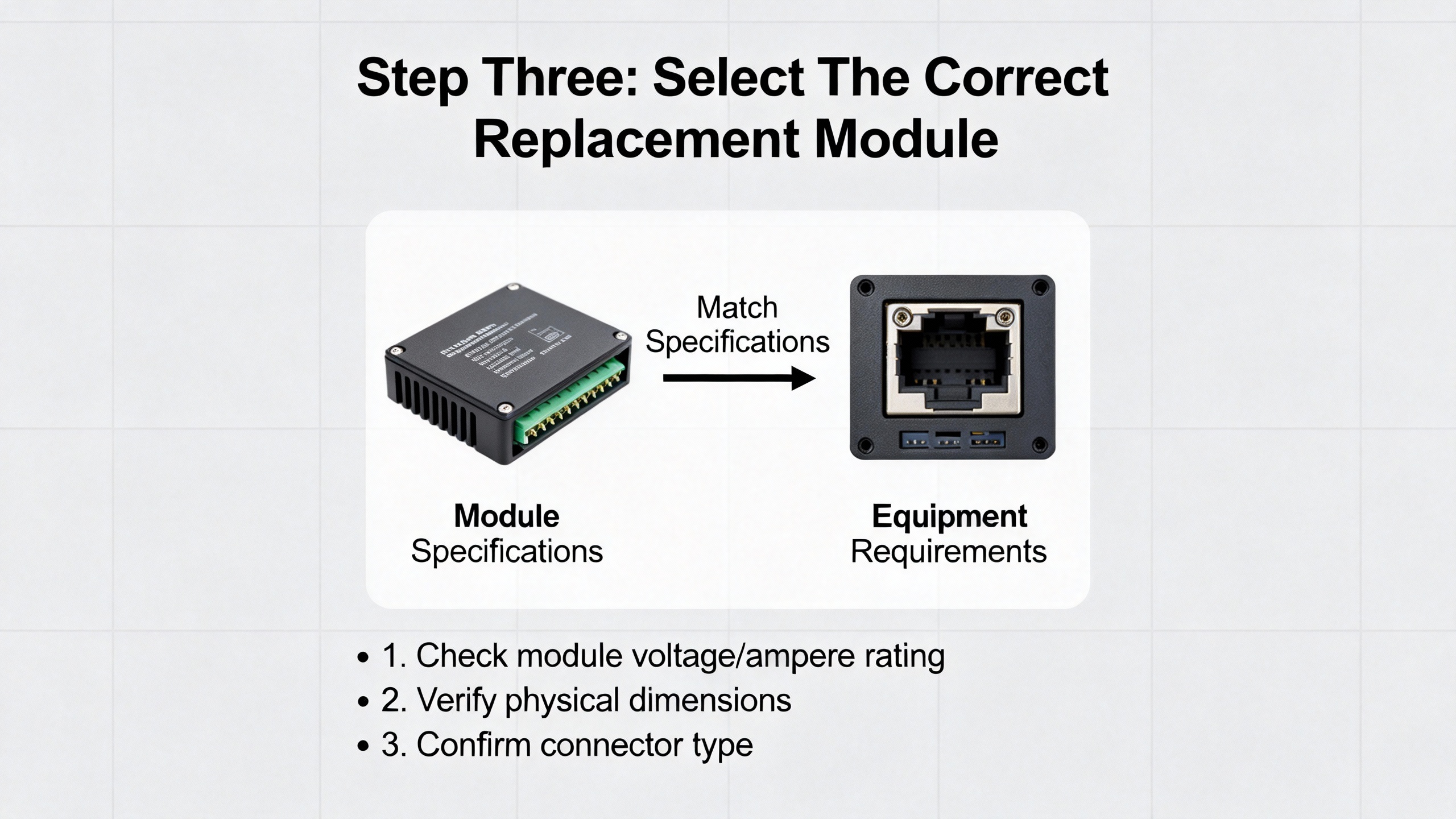
In the rush of an outage, grabbing ŌĆ£the one that fits the slotŌĆØ is a fast path to a prolonged downtime. Schneider Electric guidance is direct: when replacing an I/O module, the new module must match the original in type, model or approved successor, and I/O configuration. That includes channel count, analog versus digital type, voltage or current ranges, and any specialty functions.
NetApp documentation for AFX and FAS storage systems, while from the IT side, reinforces an important concept. They allow replacing a failed I/O module with the same type or a different compatible module, but the slot numbering and logical configuration must be carefully maintained. Awareness of slot numbers, physical labels, and logical identifiers is crucial for planning and service.
In industrial automation, that maps to verifying several details quickly. The module should match the PLC platform and backplane family. The channel density and type should match the field wiring and point database. Any safety functions, isolation rating, or specialty behavior such as highŌĆæspeed counters or motion interfaces should be identical or explicitly supported by an approved successor module.
Control Engineering and Honeywell both highlight instrumentation compatibility as a common oversight. If your failing module was wired to RTDs, thermocouples, or transmitters at a specific range, the replacement must support those signal types and ranges without making you reŌĆæengineer the loop.
In a wellŌĆæprepared urgent service, your spares shelf is already organized around these compatibility rules, not just part numbers. If it is not, the best time to fix that is right after you get through this outage.
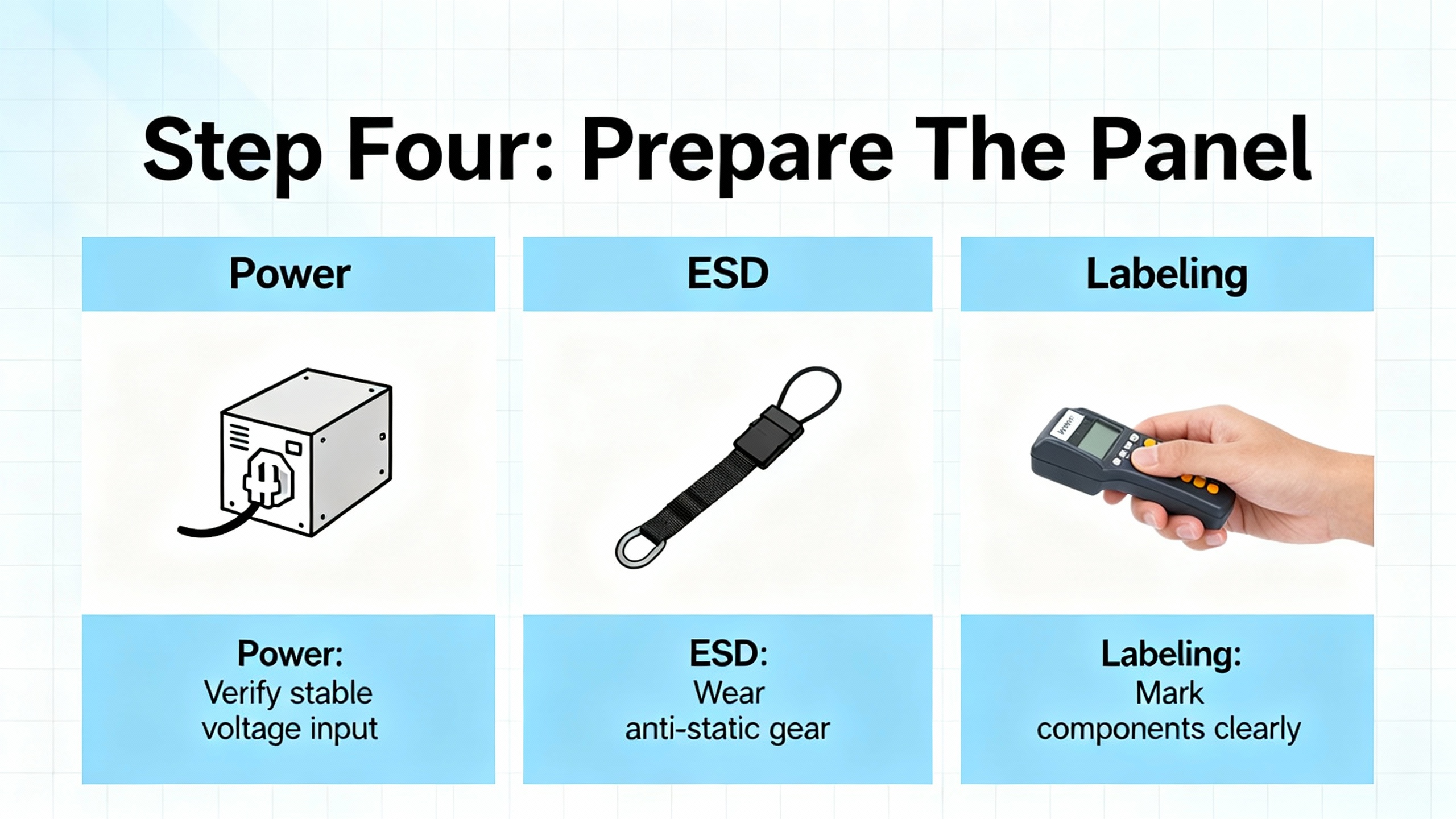
Once you have a replacement in hand, you prepare the physical environment. Schneider Electric recommends deŌĆæenergizing the panel or strictly following the manufacturerŌĆÖs documented hotŌĆæswap procedure. Even when hot swap is supported, they emphasize observing ESD precautions to avoid damaging sensitive electronics.
Control Engineering notes that poor power quality is behind a large share of vendor support calls. That means this is also the moment to confirm that the power supply feeding the rack is stable, properly sized, and not sagging under load. If modules are cycling or browning out, replacing the card will not solve the underlying issue.
Good field practice from building automation and industrial systems looks very similar. You verify lockoutŌĆætagout or other energy control as required. You ground yourself and use appropriate ESD straps or mats if the environment warrants it. You expose only the parts of the panel you need for the job.
Schneider Electric also stresses labeling modules and field wiring clearly. In an urgent replacement, most technicians focus on speed and skip documentation, but this is where you set yourself up for the next outage. Updating terminal block labels, channel numbers, and loop IDs while the panel is open avoids configuration mistakes later. When I can, I take highŌĆæresolution photos of the wiring before touching anything. If the outage is truly timeŌĆæcritical, the photos at least give you a record to reconcile after the line is back up.
Weidm├╝llerŌĆÖs uŌĆæremote materials highlight the value of modular slices and local diagnostics. With distributed I/O systems, visual LEDs per channel and per slice can help you confirm which module is actually failed, reducing unnecessary replacement and making your labeling more precise.
Physically swapping a module is usually the easy part, but under stress, people make avoidable mistakes. The mechanical procedures from IT and data center equipment illustrate the level of care that also applies to industrial racks.
LenovoŌĆÖs description of Flex System modules is typical. They specify that if a filler is present in the target bay, you open the release handles by rotating the top handle up and the bottom handle down, slide the filler out, then insert the new module, aligning it carefully and closing the handles to lock it in place. Storage vendors such as NetApp even provide location LEDs that can be turned on via remote commands so you do not pull the wrong chassis.
In a PLC cabinet, that maps to visually confirming rack address and slot, removing swing arms or terminal blocks cleanly, and avoiding stress on old wiring. The Control Engineering articles warn that fragile legacy wiring is easy to damage during upgrades, especially in cramped panels where analog and digital positions were hardŌĆæcoded into specific slots.
Opto 22 points out that some smart analog and highŌĆædensity digital modules report their type to the brain automatically. That is helpful for diagnostics, but you still need to ensure the physical module matches what the controller is expecting. If the PAC strategy expects one kind of analog module and finds another, the configuration tools will generate warnings.
During urgent replacement, I pay attention to the mechanical ŌĆ£feelŌĆØ when seating a module. A card that does not fully seat can cause intermittent faults that are far worse than a clear failure. A gentle but firm insertion until the latches click beats a forced insertion every time.
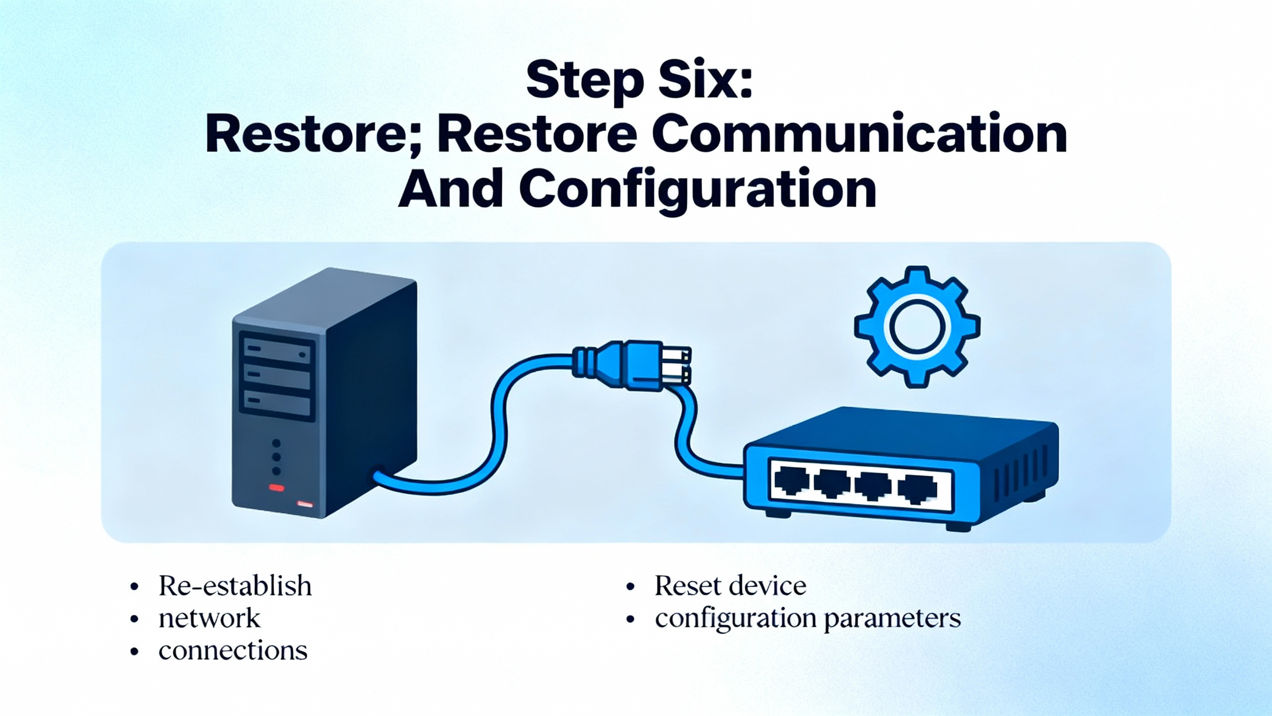
Swapping hardware is only half the job. The rest happens in the controller, HMI, and network configuration.
Schneider Electric notes that most building automation controllers automatically detect attached I/O modules at boot or rescan, but the point database must still align with the module order and addressing. If you accidentally shift module positions or change types without updating the configuration, your tags will now reference the wrong physical signals.
Siemens explains that in the ET 200SP world, even modules that are no longer configured but remain physically present may retain their previous substitute value behavior until power is cycled. That can lead to hidden interactions if you change the hardware configuration but never powerŌĆæcycle the interface module.
On EthernetŌĆæbased systems, ODVAŌĆÖs EtherNet/IP DeveloperŌĆÖs Guide recommends designing Assembly objects and I/O connections around packed, efficient data structures. After an urgent module replacement, you may be tempted to quickly drop tags directly against new module addresses, but that can fragment your cyclic I/O, multiply connection counts, and stress the network. ODVA suggests minimizing connections, packing related I/O into a small number of assemblies, and choosing RPIs that balance latency and network load. In urgent service, that means restoring the previous, tested configuration rather than improvising a new tag map while everyone is watching the downtime clock.
Trend MicroŌĆÖs TPS documentation adds a valuable operational nuance. On those systems, after a module change, their central management software can take up to about a minute to recognize and display the updated I/O state. Industrial SCADA and asset management tools can show similar delays depending on how they cache device profiles. In an urgent repair, you should allow for this recognition lag before declaring that ŌĆ£the system is not seeing the new module.ŌĆØ
Once the configuration is downloaded, you should verify that all I/O connections are healthy, watch for moduleŌĆætype mismatch warnings, and confirm that your PLC no longer reports I/O faults or rack errors. Only then is it time to move on to functional testing.
Schneider Electric stresses a basic but often neglected step: after installing a replacement module, stimulate every input and test every output associated with it, checking scaling, polarity, and failŌĆæsafe behavior. Opto 22 uses special outŌĆæofŌĆærange flags such as a default value of negative thirtyŌĆætwo thousand seven hundred sixtyŌĆæeight on analog inputs to indicate invalid readings. These are the clues you use to catch wiring problems and configuration errors before handing the system back to operations.
CoreTigo reminds us that logical failures, such as incorrect tracking of analog inputs or output control errors, can generate inaccurate data and mistimed operations even when the hardware appears healthy. So effective testing is not a single on and off per point. It is confirmation that the signal is reasonable, correctly scaled, and behaves as expected when you drive the process.
Trend MicroŌĆÖs bestŌĆæpractice guidance for I/O changes is directly applicable: after changes, test endŌĆætoŌĆæend connectivity in all modes you care about. For industrial control, that can mean automatic mode, manual or maintenance mode, and transitions, including startŌĆæups and orderly stops. The goal is to catch configuration or wiring mistakes in a controlled test, not during the first batch.
In urgent service, I typically start with quick confidence checks. I toggle each digital output from the HMI or engineering workstation and visually confirm the actuator state on the floor. For analogs, I compare readings before and after the swap where possible, or use known references or loop simulators. If the process cannot be stopped, I select test points that keep risk low but still provide clear evidence that each channel is behaving properly.
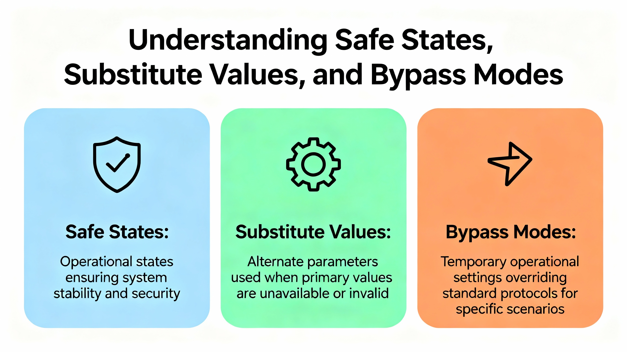
Two modern I/O concepts matter a lot in urgent replacements: substitute values and bypass behavior.
Siemens ET 200SP manages substitute values per slot. When the controller stops, connections are interrupted, or firmware is updated, output modules can be configured to hold last value, drive to a safe value, or go currentŌĆæfree. For multi hot swap operations, this behavior determines what the process sees while modules are removed and inserted. Siemens recommends explicitly planning for these states during maintenance so that automatic safe states do not conflict with process requirements.
On the network security side, Trend MicroŌĆÖs bypass I/O modules always power up in bypass mode, allowing traffic to flow through without inspection until an administrator moves them to normal mode. That bypass state persists across reboots. For process control networks, the equivalent is often hardwired bypass circuits, normally closed safety contacts, or controller logic that allows a device to run in a degraded mode while maintenance is ongoing.
When you replace modules in safety, networking, or highŌĆæavailability roles, you must understand these behaviors ahead of time. A common mistake is to assume that a new module will behave identically out of the box. In reality, it may come up in a default safe or bypass state that needs deliberate reconfiguration before the system is truly restored.
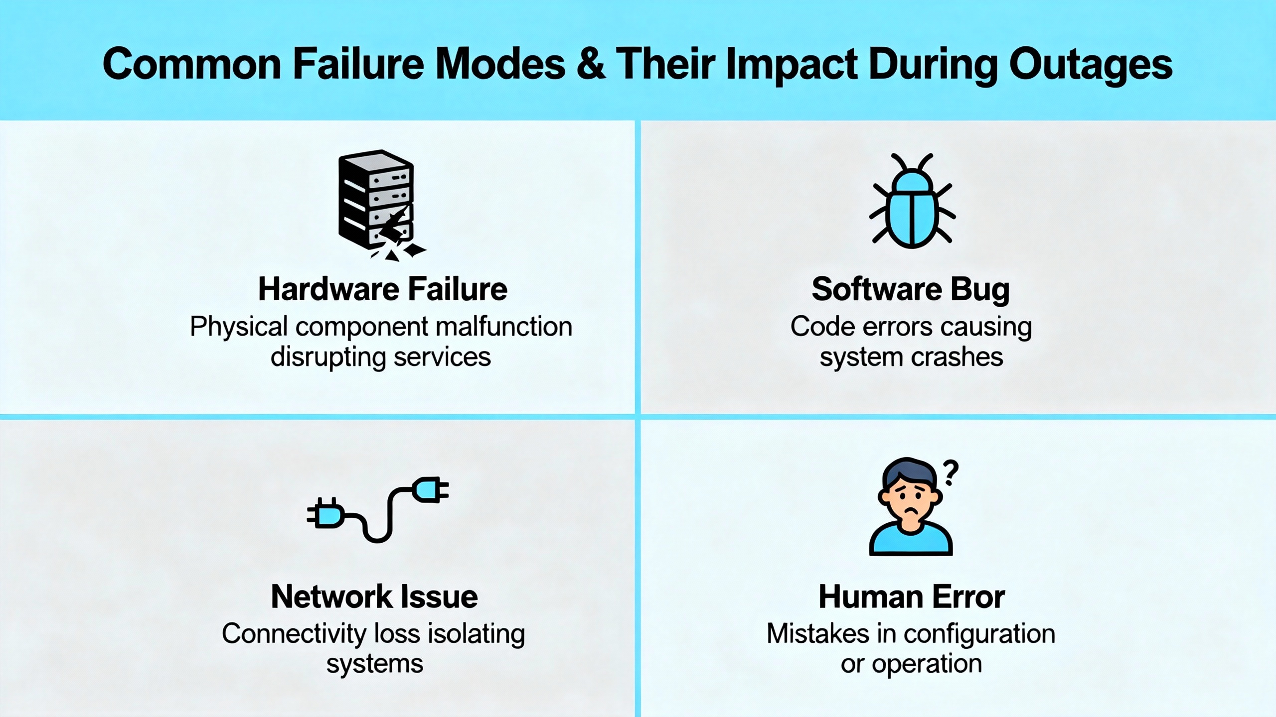
CoreTigoŌĆÖs discussion of I/O module inefficiency is a good reminder of what usually drives those 2:00 AM calls. Electrical issues such as short circuits can burn components or shut down channels. Open circuits from broken wires or loose terminals cause signal loss and miscommunication. Environmental abuse such as high temperature, humidity, corrosion, vibration, and physical impact creates latent faults that erupt later.
When you are on site for an urgent replacement, it is tempting to stop once the new module works. The more sustainable approach is to quickly scan for obvious root causes. I check for discoloration around terminals, signs of moisture, loose cable glands, and unsupported heavy cables hanging on connectors. If core power quality is questionable, I take note for followŌĆæup.
Weidm├╝llerŌĆÖs uŌĆæremote concept and similar distributed I/O systems can help here through channelŌĆælevel diagnostics and status LEDs. Modules that can report perŌĆæchannel faults, short circuits, and overŌĆærange conditions give you a faster way to identify whether the module itself failed or if a field condition stressed it to death.
At the very least, you should log what you saw. Even in a frantic outage, a few notes about suspected causes help your team decide whether to upgrade enclosures, add surge protection, or rework wiring before the next incident.
An I/O module replacement is really a communication restoration problem. ODVAŌĆÖs EtherNet/IP guidance emphasizes designing CIP objects and network architecture so that devices expose data in assembly objects with efficient I/O connections. After a disruption, it is easy to end up with fragmented tag structures, too many small connections, and aggressive RPIs that overload the network.
The Ignition and Logix bestŌĆæpractice discussion in the Inductive Automation community reinforces a similar theme. Reading directly from complex instruction data such as enhanced PID blocks can generate many separate reads and hurt communication efficiency. Instead, they recommend creating userŌĆædefined types that contain only the needed data and bridging logic inside the PLC. In the context of an urgent I/O replacement, this means that if you have to reŌĆæpoint tags because of module changes, you should preserve that efficient structure instead of letting every new tag become a oneŌĆæoff read.
Trend MicroŌĆÖs experience with configuration persistence and recognition delays through central management tools also applies to HMI and SCADA systems. After an I/O change, a server may need time to rescan device profiles or reŌĆæestablish subscriptions. Being aware of that delay avoids chasing phantom problems when the real issue is simply that the supervisory layer has not caught up.
When the urgent work is done and the system is stable, I like to schedule a followŌĆæup review of the communication design. That is when you decide whether to introduce better UDTs, adjust RPIs to keep critical I/O in the subŌĆætenŌĆæmillisecond range suggested by ODVA, or segment networks so that future module additions do not push utilization beyond safe levels.
Control Engineering repeatedly warns that I/O upgrades are highŌĆærisk projects and should be planned across time, cost, wiring, and system behavior. The second article on I/O replacement strategies goes further, describing techniques such as preŌĆæassembling and prewiring subŌĆæplates, running old and new systems in parallel, and networking controllers so they can share signals without rewiring.
Sometimes, an urgent I/O module failure is the canary in the coal mine, signaling that your platform is obsolete, spare parts are scarce, or physical constraints are too tight for ongoing maintenance. In those situations, it may still be right to perform a likeŌĆæforŌĆælike urgent replacement to get running again, but you should treat that event as the trigger for a deeper migration plan.
Options include moving to more flexible modular I/O that allows any module in any rack position, as Control Engineering recommends, or adopting modern distributed I/O such as Weidm├╝llerŌĆÖs uŌĆæremote. CoreTigo and ifm advocate for IOŌĆæLink and IOŌĆæLink Wireless approaches that provide richer diagnostics and easier reconfiguration, which can significantly speed up future troubleshooting and condition monitoring.
The key is not to turn every failure into a full project in the moment of outage. Instead, it is to deliberately capture the lessons from each urgent call and use them to design a cleaner, more maintainable architecture when the plant can spare the time.
The following table summarizes the practical differences between hot swap and cold swap approaches using behaviors drawn from Trend Micro, Siemens, Opto 22, Lenovo, and general automation practice.
| Aspect | Hot swap | Cold swap |
|---|---|---|
| Power state | Device or rack remains powered | Device or rack deŌĆæenergized |
| Vendor support | Explicitly supported on some platforms; unsupported on others such as certain Opto 22 SNAP modules | Generally supported everywhere if powerŌĆædown procedures are followed |
| Configuration impact | May reset local port settings while preserving higherŌĆælevel configuration, as described by Trend Micro; depends on platform | Often preserves configuration when replacement type matches; still platform specific |
| Process continuity | Potentially minimal downtime if substitute values and safe states are well understood, as in Siemens ET 200SP | Requires stop or outage for the affected segment or machine |
| Electrical risk | Higher risk of damage if hardware is not designed for live insertion | Lower electrical risk if proper lockout and ESD precautions are used |
| When to prefer | When vendor explicitly documents hotŌĆæswap behavior and process risk is low or manageable | When vendor guidance is unclear, process risk is high, or power issues are suspected |
This table is not a substitute for vendor documentation, but it gives a quick way to reason about the tradeŌĆæoffs during an urgent service call.
Sometimes yes, sometimes absolutely not. Vendors like Siemens support multi hot swap on specific distributed I/O platforms with wellŌĆædefined substitute value behavior. Network and IT vendors such as Lenovo and NetApp support hotŌĆæplug for their I/O modules when procedures are followed. Opto 22, on the other hand, explicitly does not recommend hotŌĆæswapping certain SNAP I/O modules even though users sometimes do it. The only safe rule is to follow the documentation for your specific platform. If you cannot find clear guidance and the process risk is significant, treat the replacement as a cold swap and plan for an outage.
The hardware swap itself is usually only a small fraction of the time. What consumes time is stabilizing the process, confirming the correct replacement module, deŌĆæenergizing equipment if needed, physically swapping the card without damaging wiring, restoring configuration, and testing all points. Trend Micro suggests that even management tools may take up to about a minute to recognize hardware changes. In real plants, a disciplined urgent replacement can range from tens of minutes to roughly an hour or more depending on access, documentation quality, and how well your spares and configurations are organized. Good preparation and clear procedures are what keep you at the lower end of that range.
Vendors such as ifm promote IOŌĆæLink as a fully digital alternative to analog wiring that avoids conversion losses and improves data quality. CoreTigo shows how IOŌĆæLink Wireless can serve as a flexible workaround when traditional I/O fails, offering plugŌĆæandŌĆæplay replacements and continuous condition monitoring. In my experience, if you see repeated failures in the same area or need better diagnostics to avoid firefighting, planning a migration to IOŌĆæLink or IOŌĆæLink Wireless around the problematic equipment is often justified. Just do that planning as a followŌĆæup project, not in the middle of an urgent repair.
Getting an I/O module replaced under pressure is not magic. It is a disciplined sequence of stabilizing the process, choosing hot or cold swap based on vendor behavior and risk, selecting the right module, protecting the hardware, restoring configuration, and testing thoroughly. When you approach urgent I/O module replacement with that mindset, you not only restore communication fast, you restore it in a way you can trust at three in the morning, when nobody wants a second outage.


Copyright Notice © 2026 mooreautomated.com All rights reserved,Moore Automated is not an authorized distributor or representative of the manufacturers featured on this website. Brand names and trademarks featured are the property of their respective owners.


Leave Your Comment