


MP 3009X
Get A Quote
Yaskawa servo drives sit right in the critical path of motion on CNC machines, robots, and automated lines. When a servo alarm pops up, the plant does not care whether it is an A.71 overload or an A.30 regenerative fault. What everyone sees is a machine that just stopped making parts. As someone who spends a lot of time in hot panels and cramped machine bases, I can say that how you reset a Yaskawa alarm matters just as much as how fast you reset it. Done correctly, you clear the fault, protect the hardware, and keep the line stable. Done carelessly, you turn a simple alarm into a cooked motor, a blown drive, or a safety incident.
This article walks through practical, field-tested procedures for resetting Yaskawa servo drive alarms. It focuses on what to do before you hit reset, the different ways you can reset alarms, and how to handle some of the more common Yaskawa alarm families. The guidance draws on YaskawaŌĆÖs own safety notes, thirdŌĆæparty troubleshooting resources, and realŌĆæworld alarm lists for Yaskawa servo and robot drives, and it is written for technicians and engineers who actually work on the floor.
Before touching a servo drive, you should be on the same page as YaskawaŌĆÖs own safety guidance. The official FAQs and technical notes around servo alarm reset are very clear: their advice is only an addition to the product manuals, not a replacement. They explicitly state that users must read and understand the product instruction manual before installing, servicing, or operating any Yaskawa product. They also emphasize that only qualified personnel should install, operate, or maintain the drive, and they remind you that incorrect work exposes you to high voltages and potential serious injury or death.
In practice, that means you should treat any alarm reset procedure as part of a controlled maintenance task, not as a buttonŌĆæmashing exercise. Lockout and tagout of upstream power, verifying the DC bus has discharged, and following the warnings and cautions in the official manual are not optional. The FAQ material also notes that documentation and FAQs cannot cover every wiring variant and machine configuration, so you should always crossŌĆæcheck against the specific servo model manual and the machine builderŌĆÖs documentation.
The legal language may feel dry, but it reflects a simple reality. Yaskawa drives sit on dangerous DC buses and can move heavy equipment instantly once an alarm disappears. Do not attempt any deeper reset method if you are not trained and authorized to work at that level.

A Yaskawa servo drive constantly monitors current, DC bus voltage, heatsink temperature, encoder feedback, and internal logic. When it detects an abnormal condition, it raises an alarm code on the display or robot teach pendant and asserts a servo alarm output. A common convention is an ALM output that goes active when a fault exists. At the same time, an alarm history buffer usually captures the last several alarms. One servo alarm guide notes histories on the order of ten entries, which is enough to see whether you are dealing with a oneŌĆæoff event or a repeating pattern.
On the input side, many servo systems provide an /ALMŌĆæRST (alarm reset) input. Once the root cause is fixed, you can assert this input from a pushbutton or PLC output to clear resettable alarms. That same alarm guide warns that certain encoder related alarms do not clear through /ALMŌĆæRST and require cycling control power instead. It also notes that resetting without removing the cause can leave the motor running under fault conditions and can damage the servo system. That aligns with YaskawaŌĆÖs own advice and is the main reason a disciplined procedure matters.
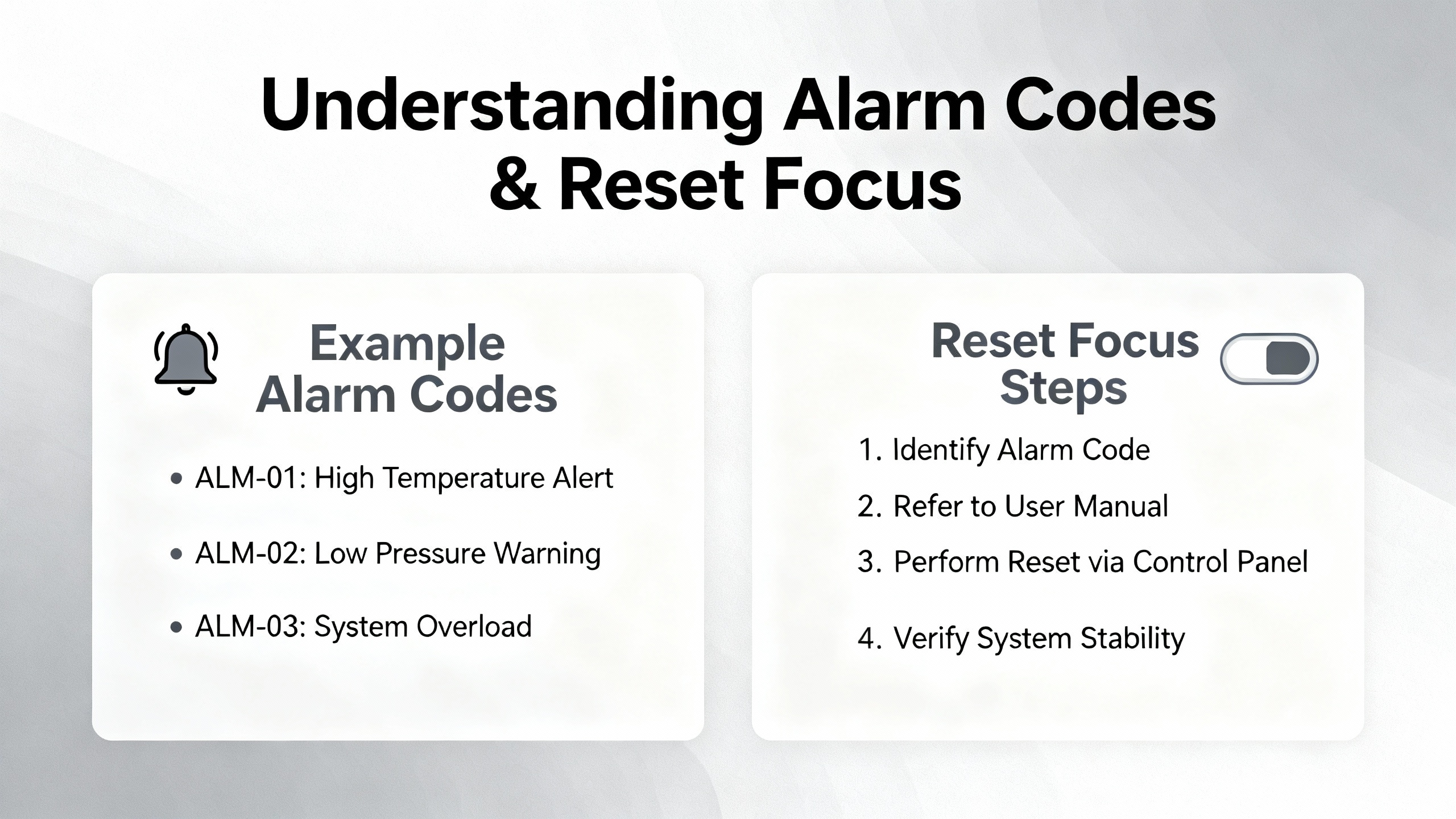
Alarm codes themselves follow a structured pattern. In Yaskawa robot servo drivers, for example, codes like A.02, A.04, A.05, A.71, A.72, and many others map to specific failures such as parameter errors, capacity mismatches, overloads, regenerative circuit issues, DC bus faults, or encoder problems. CrossŌĆævendor guides show similar families across brands: power anomalies, overcurrent and thermal protection, mechanical overload or stall, feedback errors, communication faults, parameter or memory issues, and main power stage failures. Understanding which family a particular Yaskawa alarm belongs to is the foundation for choosing the right reset strategy.
On a busy line, the temptation is to clear the alarm and ŌĆ£see if it comes back.ŌĆØ Every reliable servo troubleshooting reference warns against that habit. A servo alarm article aimed at general drives states that you should never clear an alarm before understanding it and that you should record the exact code and machine state, then consult the modelŌĆæspecific manual. A troubleshooting guide from an industrial repair house reinforces the same pattern: focus on concrete symptoms and codes first, work external causes, and only then decide whether you are resetting, repairing, or replacing hardware.
In practical terms, a disciplined workflow for Yaskawa servo alarms looks like this.
The first step is to read and record the alarm exactly as the drive reports it. That means the full alphanumeric code, any additional LED behavior, and what the machine was doing at the time. A resource that catalogs Yaskawa robot servo alarms shows codes such as A.02 for user parameter failure due to abnormal memory data, A.05 for servo motor and servo drive capacity mismatch, A.71 for highŌĆæload overload, A.72 for lowŌĆæload overload during continuous operation above rated torque, and so on. The difference between, say, A.71 and A.72 matters when you decide whether to adjust duty cycle, mechanical design, or both.
Along with the code, note the axis, direction of motion, commanded speed or torque, and whether the alarm occurred during acceleration, steady state, deceleration, or at powerŌĆæon. The MRO Electric troubleshooting article on Yaskawa drives emphasizes that fault logs and alarm histories are key for seeing repeated patterns and verifying that an issue is solved rather than just cleared temporarily.
The next step is to check for external causes, because multiple independent sources stress that many servo drive faults trace back to power quality, wiring, and mechanical issues rather than failed electronics. A servo alarm overview points to power anomalies such as unstable supply, overvoltage or undervoltage, and poor powerŌĆæline connections as primary alarm triggers. Another guide notes that undervoltage alarms often result from supply dips, missing phases, blown fuses or contactors, or loose mains terminals. For Yaskawa robot alarms like A.40 (main circuit DC overvoltage) and A.41 (main circuit DC low voltage), this is exactly where you should look.
At the same time, inspect the mechanical side. A servo drive failure guide notes that mechanical problems such as wear, looseness, or jamming in connected machinery can increase load or resistance and cause overload alarms. Yaskawa robot codes A.71 and A.72 explicitly reflect overload conditions, where torque exceeds the rating for a certain interval or under sustained operation. Removing belts or uncoupling the load to see whether the motor and drive run cleanly is a standard way to separate mechanical from electrical causes, and it is recommended in troubleshooting articles for both Yaskawa and other brands.
Motor problems can masquerade as drive faults. Field experience shared by repair specialists indicates that output short alarms and overcurrent alarms often come back to damaged or intermittently grounding motor cables. A drive error summary for Yaskawa SGDH notes A.C as output short circuit and A.E as overvoltage, and independent repair notes mention cable damage and grounded motors as frequent root causes for such alarms.
Use insulation tests and resistance checks where appropriate to confirm that motor windings are not shorted to ground and that phase resistances are balanced. For encoder related Yaskawa codes such as A.81 (absolute encoder backup battery power loss), A.83 (battery voltage drop), A.82 (encoder memory checksum error), A.84 (abnormal encoder data), A.85 (encoder overspeed at powerŌĆæon), and A.86 (encoder internal temperature too high), focus on battery condition, connector integrity, cable routing, and environmental conditions around the encoder. A servo alarm list also mentions AC8 as absolute encoder clear abnormality or incorrect multiŌĆærotation limit, and codes A.C9, A.CA, and A.Cb as communication or parameter failures between servo and encoder. For these alarms, replacing a weak battery, reseating encoder connectors, verifying encoder parameters, and reŌĆæestablishing the absolute position are the actions to perform before attempting a reset.
Parameter and command issues are another major root cause. The Yaskawa robot alarm list includes parameterŌĆærelated faults such as A.02 for user parameter failure due to abnormal EEPROM data and A.04 for parameter settings outside allowable range. It also lists A.03 for abnormal detection in the main circuit decoder or power circuit. In practice, that means you should verify that key parameters for motor model, ratings, limits, and control mode match both the motor nameplate and the machine builderŌĆÖs documentation.
A multiŌĆæbrand alarm guide advises backing up parameter sets, using vendor initialization or reset functions where available, and then restoring only necessary values to avoid rewriting readŌĆæonly or unsupported items. For Yaskawa drives, that translates to capturing the existing parameter set before making changes and avoiding random edits in an attempt to clear a stubborn alarm. On the command side, several Yaskawa robot alarms relate to input quality, such as A.b1 for speed command A/D converter fault, A.b2 for torque command A/D converter fault, and A.bF as a general system alarm. If these codes appear, you should confirm the integrity and scaling of analog signals or fieldbus commands, not just reset and hope the drive ŌĆ£forgetsŌĆØ the problem.
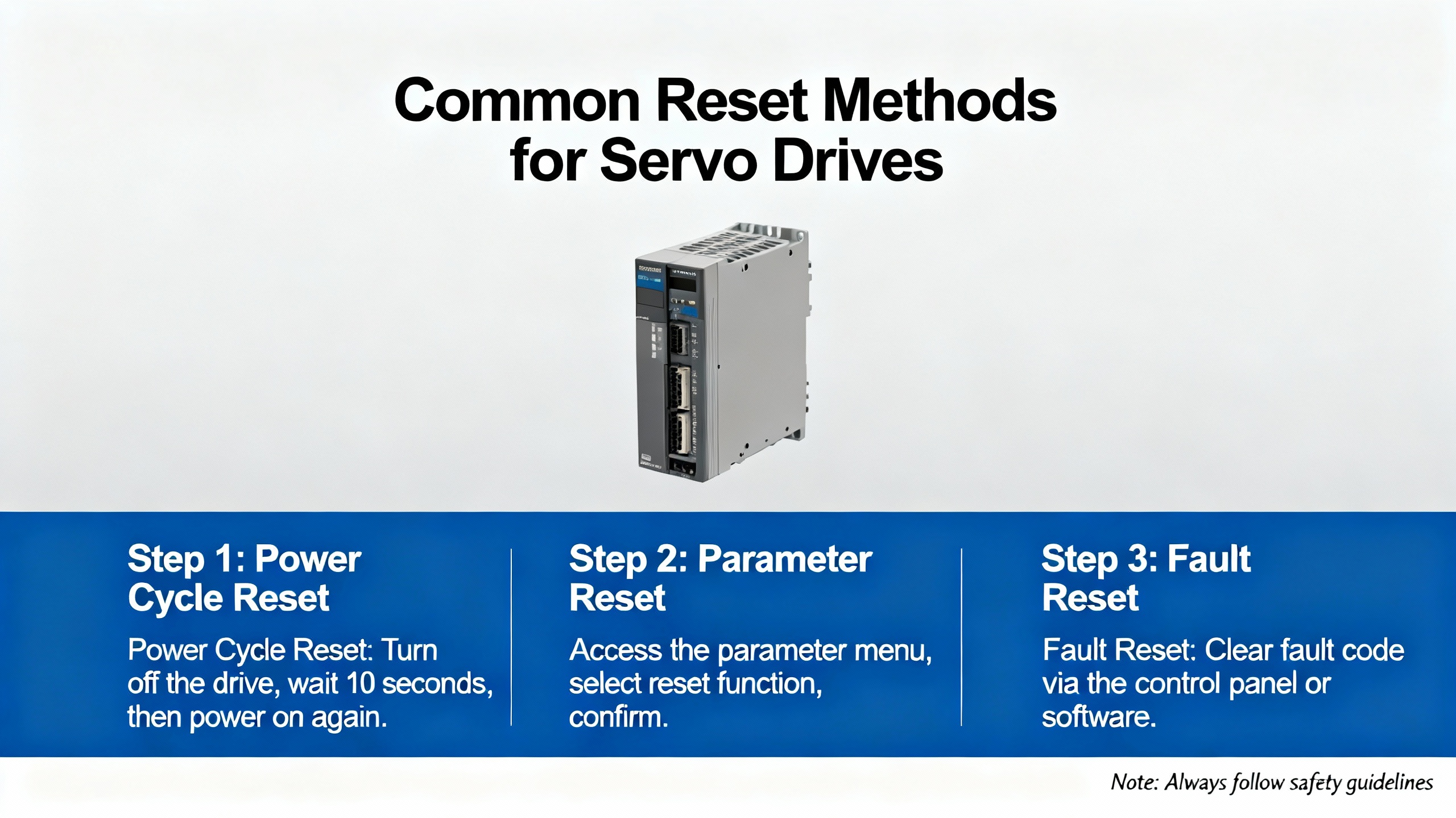
Only after the root cause has been addressed should you reset the alarm. A general servo alarm article outlines a safe baseline procedure: power off the drive in a controlled way, review alarm information against the code list, troubleshoot based on the cause, confirm that the fault is eliminated, then power on again and check for remaining alarms. If alarms persist on powerŌĆæup, it suggests using brandŌĆæspecific reset methods such as a manual reset key on the drive, a reset command from the controller, or builtŌĆæin automatic reset modes after fault clearance.
Different reset mechanisms have different implications. Some are gentle and fully controlled by the PLC or robot controller. Others, such as power cycling, stress components and can even be involved in causing certain faults. The rest of this article looks at those methods in more detail.
Servo alarm references and vendor FAQs describe several ways alarms are typically reset. YaskawaŌĆÖs own FAQ material around servo alarm reset focuses largely on safety and qualified personnel, but crossŌĆæreferencing with servo drive alarm guides and encoder reset procedures makes it clear what practitioners actually use on the floor.
Many servo systems allow alarms to be reset directly from an operator panel. A servo alarm article that describes a generic servo system notes that alarms can be reset by pressing the up and down keys simultaneously on the panel operator. While that example is associated with a particular servo brand, the pattern is similar on many YaskawaŌĆæbased systems where the frontŌĆæmounted digital operator or the robot teach pendant includes a reset or clear function.
The advantage of a panel reset is that it is quick and does not require rewiring or PLC logic changes. It also tends to respect whatever interlocks the manufacturer has built into the operator. The downside is that it is easy for operators to press the panel reset without recording the alarm code or verifying that the root cause has been removed. If you rely heavily on panelŌĆæside resets, build a discipline that requires technicians to log the code and conditions before clearing the alarm and to check the alarm history afterward.
A more controlled approach is to wire a dedicated reset input from your safetyŌĆæapproved control system. The servo alarm guide that discusses ALM and /ALMŌĆæRST shows this pattern clearly. Once the alarm condition is eliminated, asserting /ALMŌĆæRST allows the drive to clear faults that are designed to be resettable. This is typically wired to a PLC output, panel pushbutton, or robot controller output, and the machine sequence logic decides when it is safe to issue a reset.
The benefit is that you can coordinate alarm reset with other actions, such as verifying that eŌĆæstops are released, guards are closed, and axes are in a safe position. However, the same source warns that encoderŌĆærelated alarms often ignore /ALMŌĆæRST and only clear when control power is cycled. Another limitation is that the reset input can be overused: poorly written PLC code that automatically pulses reset as soon as an alarm appears can mask serious problems and create repeating, hardŌĆætoŌĆætrace fault cycles. In a wellŌĆædesigned cell, the reset input is only activated as part of a deliberate recovery sequence that mirrors the steps laid out earlier.
Power cycling is the blunt instrument of servo resets. The general servo alarm reset article notes that, after the root cause is fixed, you can power the drive off and then back on to clear many alarms. Several YaskawaŌĆæfocused troubleshooting guides also assume that once wiring or load issues are corrected, a power cycle will return the drive to a ready state.
There are two problems with leaning on this too heavily. First, frequent on and off switching stresses the surge current limiter and main power circuitry. Yaskawa robot alarm A.74, defined as surge current limiter overload due to frequent switching of the main power supply, exists for exactly that reason. Second, power cycling often removes valuable evidence. Some drives clear parts of their alarm history or detailed diagnostics at powerŌĆæoff, leaving you with only the current code but not the sequence that led up to it.
Automatic reset modes are another variant. Some servo drives, once configured, can attempt an automatic reset of certain transient alarms. A crossŌĆævendor guide mentions such capabilities generically but stresses that you must review the drive manual to understand which alarms can be safely autoŌĆæreset and under what conditions. For safetyŌĆæcritical axes or heavy mechanical loads, relying on automatic reset can be risky unless the system integrator has designed the entire sequence around it.
Absolute encoder alarms deserve their own treatment because they affect position data and homing behavior. A detailed article from Precision Zone describes a method, specifically named Method 2, for clearing A.00 or A.81 alarms on Yaskawa Sigma I servo drives with 12ŌĆæbit absolute encoders when the standard method fails. According to that description, this method applies to motors whose nameplate starts with SGMG and includes a trailing W after the kilowatt rating, indicating a 12ŌĆæbit absolute encoder.
The procedure as explained begins with prerequisites. Before attempting the reset, you must confirm that the battery, encoder, and encoder cable are in good condition. Precision Zone notes that you need a pushŌĆæbutton box wired into the CN2 connector cable, and they mention that they sell a kit or can modify the cable inŌĆæhouse if the user cannot solder the pushbutton. With the motor connected, you power on the drive and let it run for about three minutes, which allows the drive and encoder logic to stabilize. Then you press and hold the added pushbutton for at least three seconds, with the recommendation to hold it for roughly fifteen to thirty seconds to improve the success rate. After that, you power cycle the drive and check whether the alarm has cleared and whether the motor can be jogged normally.
Precision Zone reports that it is common for this reset not to work the first time and advises repeating the procedure three to four times if necessary. If the alarm is still present after several attempts, their guidance is to shortŌĆæcircuit terminals P and S for at least five minutes, then repeat the same procedure again. In most cases, they state, this clears the alarm. If alarms persist even after shorting P and S and repeating the steps, they recommend contacting their technical support for further troubleshooting.
This is a specialized method, and it is important to highlight what it implies. Clearing A.81 and similar absolute encoder alarms does not magically restore position data. By definition, an absolute encoder backup battery power loss erases stored position. That means after such a reset, you must follow the robot or machine builderŌĆÖs procedure to reŌĆæestablish the machineŌĆÖs reference and any multiŌĆæturn limits, and you must update any safetyŌĆærelated position checks that rely on the encoderŌĆÖs absolute counts.
Once you understand the categories and reset options, it becomes easier to decide how to respond to specific Yaskawa alarm codes. The following sections group several common robot and servo alarms by their nature and summarize the primary corrective focus once the alarm appears.
Alarms such as A.02, A.03, and A.04 revolve around parameters and internal data validity. The Yaskawa robot alarm list describes A.02 as user parameter failure due to abnormal EEPROM data and A.04 as user parameter settings outside the allowable range. A.03 relates to abnormal detection in the main circuit decoder or power circuit. When these alarms occur, resetting alone is meaningless. The correct approach is to check whether recent parameter changes were made, compare the current parameter set to a known good backup, and restore or correct values as required. The multiŌĆævendor alarm guideŌĆÖs advice to back up parameters and to avoid editing readŌĆæonly items is especially relevant here.
A.05 flags a servo motor and servo drive capacity mismatch. The alarm list describes this as a combination alarm where the drive and motor capacities do not match. In practice, you should verify model numbers, ratings, and encoder types against the driveŌĆÖs allowable combinations. Clearing the alarm will not fix a genuinely mismatched pair.
Overload and thermal alarms protect the motor and drive from sustained stress. Yaskawa robot alarms A.71 and A.72 cover highŌĆæload overload and lowŌĆæload overload under continuous high torque respectively. Alarm A.10 signals overcurrent through the IGBT radiator that causes overheating, and A.7A is defined as servo radiator overheating. A separate servo alarm guide notes that drive heatsink overtemperature in some vendors occurs around 239┬░F for certain frames and around 257┬░F for larger ones; the exact values for Yaskawa drives are model dependent and found in the official manuals, but the practical implications are similar.
For these alarms, recommended responses include reducing the mechanical load, adjusting duty cycle, checking for binding or misalignment, and improving cabinet ventilation and drive cooling. Cleaning filters and heatsinks, ensuring fans actually run, spacing drives so that airflow is not obstructed, and checking ambient temperature inside the enclosure are all part of the resetŌĆæbeforeŌĆærestart process. Only after temperatures are back in range and loads have been corrected should you reset and test. Treating overload or thermal alarms as a nuisance and repeatedly resetting them guarantees premature failures.
Regenerative and braking alarms occur when the system cannot safely dissipate energy returned from the load. The Yaskawa robot list defines A.30 as regenerative circuit or resistor failure and A.32 as regenerative overload when returned energy exceeds resistor capacity. It lists A.73 as dynamic brake overload when rotating energy exceeds brake resistance and A.74 as surge current limiter overload due to frequent switching of the main power supply.
For A.30 and A.32, standard recommendations include inspecting the regenerative resistor, verifying wiring, and replacing components if they are damaged or undersized. A crossŌĆævendor alarm guide notes that overvoltage and regenerative faults often follow rapid deceleration of highŌĆæinertia loads or overhauling axes, and that properly sizing the braking resistor and softening decel ramps eliminated most trips on a packaging line in one documented case. For A.73, you should examine the dynamic brake circuit and the mechanical deceleration profile. Alarm A.74 is essentially a warning that frequent on and off switching is overstressing the surge limiter, which brings us back to the earlier point that power cycling is not a harmless reset method.
DC bus and power supply alarms highlight upstream issues. A.40 represents main circuit DC overvoltage, while A.41 is main circuit DC low voltage. A.F1 indicates a power line underŌĆæphase where one supply phase is missing. CPF00 is described as an operatorŌĆōservo transmission error, indicating a communication fault between operator and drive.
In response, check input voltage with a meter under load, inspect mains terminals for looseness or discoloration, verify fuses and contactors, and correct any missing phase conditions. For CPF00 and similar communication alarms, you should examine operator and encoder communication cables and connectors, check node addresses and baud rates where fieldbus is involved, and ensure proper termination. A servo alarm article notes that RSŌĆæ485 Modbus links can run to about 4,000 ft when wired and terminated correctly, but that long runs require careful shielding and routing to avoid noiseŌĆæinduced communication faults.
Encoder and battery alarms require both electrical and dataŌĆæintegrity responses. As already mentioned, A.81 and A.83 point to absolute encoder backup battery loss or low voltage, A.82 and A.84 indicate encoder memory or data errors, A.85 flags encoder overspeed at powerŌĆæon, and A.86 reports encoder internal temperature too high. Alarm AC8 indicates absolute encoder clear abnormality or incorrect multiŌĆærotation limit setting, and A.C9, A.CA, and A.Cb cover communication failure between servo and encoder, encoder parameter failure, and encoder feedback error or incorrect communication content respectively.
Recommended steps, drawn from the Yaskawa robot alarm list and servo alarm guides, include replacing low or depleted batteries, checking encoder wiring and connectors for looseness or damage, verifying encoder parameters and multiŌĆærotation limits, and reŌĆæestablishing the absolute position if data has been erased. Where encoders are mounted in hot environments, you should also verify that ambient temperature is within specification and that no external heat sources are driving the encoder beyond its thermal limits. Resetting these alarms without fixing the underlying electrical or configuration problem can lead to repeat faults and loss of positional trust.
Finally, motion and command related alarms tell you that something about the commanded movement or position error is outside the driveŌĆÖs limits. Yaskawa robot alarm A.51 signals motor overspeed, while A.C1 indicates servo overspeed with the motor out of control. Alarm A.d0 flags position error pulse overflow where deviation exceeds parameter Pn505. Together with A.b1 and A.b2, which reflect speed and torque command A/D converter faults, and A.bF, which is a general system alarm, these codes point toward either overly aggressive motion profiles, incorrect tuning, or deeper system faults.
The Yaskawa servo troubleshooting article from MRO Electric notes that positioning errors, oscillations, and overshoot are often tied to feedback problems, incorrect PID tuning, or mechanical wear and misalignment. On the reset side, you should first adjust motion profiles to reasonable acceleration and speed, inspect gears and couplings for backlash or play, and verify tuning parameters. Only then should you clear these alarms and execute lowŌĆæspeed test moves while watching for residual oscillation or following error.
The table below summarizes several of the Yaskawa robot servo alarm codes mentioned earlier and highlights the primary focus before performing a reset. The descriptions are paraphrased from the Yaskawa robot alarm list and related servo alarm guides.
| Alarm code | Category and meaning (per published lists) | Reset focus after root cause is addressed |
|---|---|---|
| A.02 | User parameter failure due to abnormal EEPROM data | Compare parameters to a known good backup, correct corrupted or outŌĆæofŌĆærange values, then reset |
| A.04 | User parameter settings outside allowable range | Bring parameters back into allowable ranges, avoid unsupported combinations, then reset |
| A.05 | Servo motor and servo drive capacity mismatch | Verify motor and drive model compatibility and ratings, correct any mismatch before resetting |
| A.10 | Overcurrent through the IGBT radiator causing overheating | Inspect for shorts on motor side, excessive load, and inadequate cooling, fix issues, then reset |
| A.71 | HighŌĆæload overload where torque exceeds rating for several seconds or tens of seconds | Reduce peak load, adjust mechanical design or duty cycle, then reset and test under controlled conditions |
| A.72 | LowŌĆæload overload under continuous operation above rated torque | DeŌĆærate continuous load, review cycle times and duty, verify motor sizing, then reset |
| A.7A | Servo radiator overheating | Improve ventilation, clean heatsinks and filters, verify fan operation and ambient temperature, then reset |
| A.30 | Regenerative circuit or resistor failure | Inspect and, if needed, replace regenerative resistor and wiring, then reset and test decel moves |
| A.32 | Regenerative overload where returned energy exceeds resistor capacity | Increase resistor capacity or soften decel ramps, then reset and validate with worstŌĆæcase moves |
| A.73 | Dynamic brake overload when rotating energy exceeds brake resistance | Review braking method and mechanical inertia, correct any mismatches, then reset |
| A.74 | Surge current limiter overload due to frequent ON/OFF switching of main power | Reduce power cycling frequency, correct start/stop logic, allow rest time, then reset |
| A.40 | Main circuit DC overvoltage | Check line overvoltage and regenerative events, verify braking resistor, correct issues, then reset |
| A.41 | Main circuit DC low voltage | Diagnose supply dips, missing phases, loose terminals, or blown fuses, fix them, then reset |
| A.F1 | Power line underŌĆæphase (one supply phase not connected) | Restore full threeŌĆæphase supply with correct wiring and fusing before any reset |
| CPF00 | OperatorŌĆōservo transmission error | Check operator and communication cable connections and settings, correct faults, then reset |
| A.81 | Absolute encoder backup battery power loss, position data erased | Replace battery, reŌĆæestablish reference position and multiŌĆæturn data, then reset using the prescribed method |
| A.83 | Absolute encoder battery voltage drop | Replace weak battery, confirm voltage, and only then reset |
| A.82 | Encoder memory checksum error | Inspect encoder and cable, replace if faulty, and reŌĆæinitialize encoder data before reset |
| A.84 | Abnormal encoder data | Troubleshoot cabling, connectors, and encoder, correct faults, then reset and reŌĆæhome as required |
| A.85 | Encoder overspeed at powerŌĆæon | Review mechanical coupling and startup sequence, correct causes of overspeed, then reset |
| A.86 | Encoder internal temperature too high | Improve cooling around the encoder or reduce thermal load, allow temperature to drop, then reset |
| AC8 | Absolute encoder clear abnormality or incorrect multiŌĆærotation limit setting | Verify and correct encoder clear process and multiŌĆærotation parameters, then reset and reŌĆæhome |
| A.C9 | Communication failure between servo and encoder | Reseat connectors, correct wiring and shielding, and verify configuration before resetting |
| A.CA | Encoder parameter failure | Correct encoder parameter settings and restore valid data prior to reset |
| A.Cb | Encoder feedback error or incorrect communication content | Fix wiring, shielding, or encoder hardware, then reset and verify stable motion |
| A.b1 | Speed command input A/D converter fault | Check command signal source and wiring, correct electrical issues, then reset |
| A.b2 | Torque command input A/D converter fault | As with A.b1, inspect torque signal path, correct faults, then reset |
| A.bF | General system alarm indicating a servo failure | Use alarm history and diagnostics to identify specific cause, correct it, then reset |
| A.51 | Motor overspeed | Reduce commanded speed and adjust profiles, check for mechanical overŌĆærun, then reset |
| A.C1 | Servo overspeed, motor out of control | Investigate feedback, tuning, and mechanical coupling, correct issues, then reset cautiously |
| A.d0 | Position error pulse overflow where deviation exceeds Pn505 | Adjust tuning and motion profile, check for mechanical binding or backlash, then reset and test |
Servo alarm references and troubleshooting guides repeatedly emphasize the value of alarm history. The servo alarm article that discusses ALM and alarm history notes that systems typically store the most recent alarms, making it possible to see whether you are dealing with a oneŌĆætime event or a pattern. The general servo troubleshooting workflow from Industrial Automation Co and the YaskawaŌĆæfocused guide from MRO Electric both push the same point: document what you see and what you do.
In practical terms, that means recording alarm codes, axis, time, operating mode, and corrective actions, and periodically reviewing that log. If you notice repeated A.30 and A.32 regenerative alarms on the same axis during deceleration, that is a strong signal to revisit braking resistor sizing and decel ramps instead of continuing to reset. If you see A.81 and A.83 absolute encoder battery alarms recurring more frequently than expected, it is time to inspect battery quality, environment, and maintenance intervals.
Preventive measures recommended in servo alarm guides include routine inspection of terminals and connectors for looseness, periodic insulation resistance checks on motors and cables, cleaning cabinets, backing up parameter sets after commissioning, and keeping copies of relevant Yaskawa manuals with the machine. These actions do not eliminate alarms, but they reduce the number of surprises and make reset decisions more informed.

Q: Is it safe to just power cycle a Yaskawa servo drive when an alarm appears? A: Power cycling is a valid reset method but should not be your first move. Alarm guides warn that frequent on and off switching can overload surge limiters, which is exactly what Yaskawa alarm A.74 represents. More importantly, cycling power without understanding the code discards context and may leave serious issues unresolved. You should capture the alarm, correct the root cause, and then use a controlled reset method, whether that is a panel reset, /ALMŌĆæRST input, or a single power cycle.
Q: Do I always need to reŌĆæhome after clearing an encoder battery alarm like A.81? A: The Yaskawa robot alarm list notes that A.81 indicates absolute encoder backup battery power loss and that position data is erased. That means you should expect to reŌĆæestablish the machine reference or home position and verify multiŌĆæturn limits after clearing the alarm. Skipping that step can leave safety zones and positionŌĆæbased logic relying on invalid data.
Q: When should I stop troubleshooting and involve Yaskawa or a repair provider? A: If alarms indicate internal hardware failure, if the same alarm returns quickly after proper corrective actions, or if specialized procedures like the absolute encoder reset method from Precision Zone fail to clear A.00 or A.81, it is time to involve the OEM or a qualified repair provider. Many drives store fault histories and provide detailed diagnostics that specialist technicians can interpret more effectively, and repair services often back their work with multiŌĆæyear warranties, which is cheaper than repeated unscheduled downtime.
At the end of the day, resetting a Yaskawa servo alarm is not about finding the fastest way to turn a red light green. It is about understanding what the drive is telling you, fixing the underlying problem, and then using the right reset method so the machine goes back into production safely and stays there. That is how you keep both the plant and the servo packs happy.


Copyright Notice © 2026 mooreautomated.com All rights reserved,Moore Automated is not an authorized distributor or representative of the manufacturers featured on this website. Brand names and trademarks featured are the property of their respective owners.


Leave Your Comment