


MP 3009X
Get A Quote
When a Woodward governor stops ŌĆ£talkingŌĆØ properly to the rest of your system, you feel it immediately on the plant floor. Turbines refuse to load, generators hunt or trip, diesel engines overspeed or stall, and the control room fills with alarms that all sound the same: something in the communication chain has gone wrong. As someone who spends a lot of time in front of live panels and hot engines, I have learned that most ŌĆ£communication errorsŌĆØ are not mysterious firmware ghosts. They are usually very real electrical, hydraulic, or configuration problems that you can localize and fix with a structured, noŌĆænonsense approach.
This article walks through how Woodward governor systems actually ŌĆ£communicate,ŌĆØ what typical communication failures look like in the field, and a practical workflow to troubleshoot them safely. The guidance draws directly from manufacturerŌĆæstyle material on Woodward governors, diesel generator electronic governors, and real-world case studies shared by experienced engineers, including a detailed Woodward 505 steam turbine issue discussed on Control.com, as well as troubleshooting guidance compiled by DieselGeneratorTech, Davidson Sales, HelloTroubleshooting, and other technical sources.
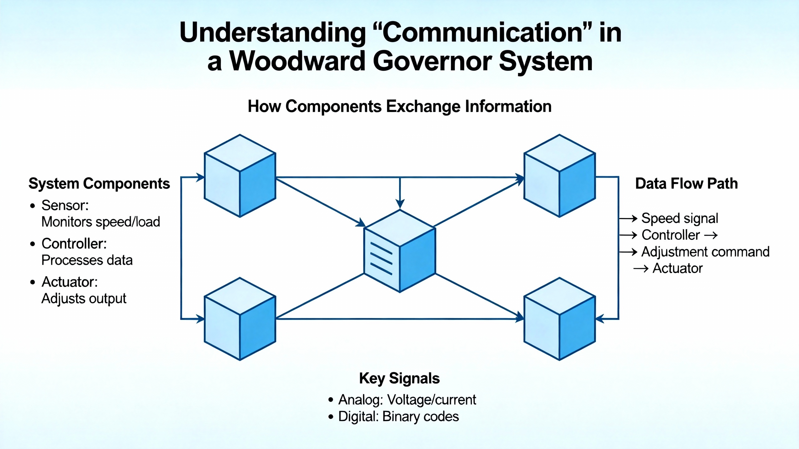
In everyday plant language, communication error often gets used narrowly to mean a failed serial link or lost Ethernet connection. In governor applications, the idea is broader. A Woodward governor has to receive accurate information about speed and load, process that information internally, and send credible commands to actuators or fuel systems. Any break or distortion anywhere along that path is, in practical terms, a communication failure.
For diesel and gas engines with electronic governors, one article from DieselGeneratorTech describes the governor as an automatic device that adjusts fuel delivery at the injection pump based on load changes so the engine runs at stable speed. Sensor signals feed the controller, the controller drives an actuator, and the actuator moves the fuel rack. If the sensor wiring is open, the actuator coil is damaged, or the controller cannot ŌĆ£seeŌĆØ the setpoint, the physical fuel system has lost communication with the control logic even if there is no digital bus in sight.
On modern Woodward platforms such as the A8251ŌĆæ758 digital governor, the signal chain is more complex but conceptually similar. The governor monitors inputs (speed sensors, analog references, digital commands), runs its internal algorithms, and outputs control signals (often 4ŌĆō20 mA to an actuator or electroŌĆæhydraulic module). HelloTroubleshooting emphasizes that power supply integrity, signal voltages, and upŌĆætoŌĆædate firmware are just as critical to the governorŌĆÖs operation as any mechanical component. When the diagnostic tools on such a unit report a communication error, they are complaining about breaks in these control paths.
Even for larger steam turbines with Woodward 505 governors, the core principle holds. In the Control.com case, the 505 generates a 0ŌĆō100 percent demand that a converter maps to a 4ŌĆō20 mA signal for an electroŌĆæhydraulic governor (EHG). The EHG then drives a Voith I/H converter, which turns current into hydraulic pressure at the steam valve actuator. There is no direct valve position feedback into the 505. If the 505 internal reference or demand stops moving while the setpoint changes, the communication failure is inside the governor logic. If the 4ŌĆō20 mA signal or hydraulic pressure does not follow the 505 output, the break is downstream in the analog or hydraulic communication chain.
In every one of these cases, ŌĆ£communicationŌĆØ is not just a networking protocol. It is the flow of trustworthy information and energy between sensors, controls, and final elements.
To troubleshoot communication issues effectively, it helps to recall what governors are trying to achieve. Power-system control literature, such as the governor overview published on Fiveable, explains that governors regulate turbine speed and generator output to stabilize system frequency. They compare the measured speed or frequency to an internal reference and adjust prime mover power to reduce the error.
The same source describes three broad classes of governors. MechanicalŌĆæhydraulic units use spinning flyballs, pilot valves, and hydraulic amplifiers to convert small speed changes into valve or wicketŌĆægate motion, with mechanical feedback to avoid overshoot. ElectroŌĆæhydraulic governors blend electronic control with hydraulic actuation, combining faster dynamic response with robust power. Digital or electronic governors (like many modern Woodward models) use microprocessors and PIDŌĆæstyle algorithms, often with droop characteristics so parallel machines can share load stably.
From a communication perspective, each architecture has its own weak points. Mechanical-hydraulic units depend on oil cleanliness, mechanical linkages, and pilot-valve clearances. Electro-hydraulic and electronic governors add wiring integrity, electromagnetic noise immunity, and software configuration to the list. If you understand which elements are supposed to talk to each other, you can methodically test that communication path.
The table below summarizes where communication can fail in typical analog versus digital governor paths.
| Aspect | Analog / electroŌĆæhydraulic path | Digital / electronic path |
|---|---|---|
| Incoming information | Speed pickup, frequency signal, pressure or position | Speed sensors, analog inputs, discrete I/O, sometimes network commands |
| Internal processing | Mechanical feedback, fixed gains | Configurable algorithms, PID, droop, protective limiters |
| Outgoing command | Hydraulic pilot pressure, mechanical linkage | 4ŌĆō20 mA to actuator, PWM, digital outputs |
| Common failure points | Blocked oil ports, worn linkages, contamination | Power supply faults, wiring breaks, noisy signals, software misconfig |
A communication error is simply the situation where one of these elements is no longer transmitting or receiving the right information.
In a wellŌĆæbehaved governor system, you see proportional, stable, and repeatable responses: push the setpoint up, and load increases; pull it down, and the machine unloads; step changes in load create momentary speed deviations that the governor corrects without hunting. When communication breaks down, patterns emerge that are surprisingly consistent across applications and brands.
The Control.com discussion of a misbehaving Woodward 505 illustrates one such pattern. After generator synchronization, operators attempted to raise load. Instead of increasing valve demand, the 505 output actually decreased, and the steam valve closed. On a later attempt, when the load setpoint was aggressively ramped toward about 9 MW, the actuator command increased enough that the unit stayed online, but reverse power protection came into play. Logs showed the 505 internal reference dropping from roughly thirtyŌĆætwo percent to twentyŌĆætwo percent when operators commanded more load. The valves and hydraulic system had already been proven with stroking tests, so the symptom pointed to an internal communication issue between the governor reference logic and its output demand.
DieselGeneratorTechŌĆÖs troubleshooting guide for diesel genset electronic governors shows other classical communicationŌĆæfailure symptoms. If the engine will not start at all, the very first checks involve verifying power supply voltage, confirming the speed sensor is not open (with an expected resistance around four hundred fifty ohms), and checking actuator coil resistance (typically around four ohms) with a multimeter. An open sensor or actuator coil represents a total loss of communication between the governor and the engineŌĆÖs physical speed feedback or fuel rack.
Another symptom is engine speed instability or hunting. The same guide lists causes such as large clearance or lag in the transmission rod between actuator and rack, overload on the engine, excessive gap at the speed sensor, or incorrectly connected shielding. All of these degrade the quality of the signal the governor receives or sends. When the feedback path is delayed, noisy, or intermittent, the controllerŌĆÖs corrective actions arrive late or distorted, and speed wanders.
Davidson Sales, in their installation and calibration advice for electronic governors, emphasizes constant or intermittent speed instability and erratic calibration response as tellŌĆætale signs of electrical noise. They note that noise from radio equipment, magnetic fields, pulsating currents, and heavy relays can interfere with power and speedŌĆæsensing circuits. If the governor briefly ŌĆ£seesŌĆØ a false speed, it will correct for a disturbance that never existed. In practice, that feels like random communication errors, often triggered when nearby loads or equipment switch on and off.
On digital Woodward models like the A8251ŌĆæ758, HelloTroubleshooting describes nonŌĆæresponse, inconsistent performance, and repeated error codes as key indicators of power, signal, or software issues. Some of these codes explicitly relate to communication or firmware problems. When a unit reports such a fault, you must treat it as a communication error inside the controller itself, not just a wiring problem outside.
Finally, condition-monitoring literature for mechanical governors, such as the general guidance summarized from RenewableEnergyWorld, notes that sluggish response, deadband, and overshoot often trace back to oil contamination, internal leakage, or worn linkages. While these are mechanical issues, they still represent poor ŌĆ£communicationŌĆØ between the speed-sensing mechanism and the final control element.
Once you can recognize communicationŌĆætype symptoms, the next step is to understand the likely causes and where to look first.
Power and grounding problems are the most basic. The A8251ŌĆæ758 troubleshooting article underscores that you should always confirm proper power supply before diving deeper. Many Woodward governors expect a stable twentyŌĆæfour volt DC supply, and some signal inputs sit around five volts DC, but you must always compare to the specific manual. Loose or corroded terminals, weak power sources, and shared returns contaminated with voltage drops all degrade the governorŌĆÖs ability to sense or drive its I/O correctly. A unit that appears to have ŌĆ£communication errorsŌĆØ with sensors or actuators may simply be starving for clean power.
Sensor and feedback wiring comes next. The DieselGeneratorTech guidance gives practical test points: check the speed sensor with a multimeter in resistance mode and expect a value around four hundred fifty ohms; inspect the mounting clearance to ensure the pickup can reliably detect gear teeth. Confirm the continuity and insulation of the cables between the sensor and the controller. If the measured resistance is infinite, or if jiggle tests make the reading jump around, the speed information reaching the governor is compromised. Actuator coils deserve similar attention. Around four ohms of resistance is typical for some electronic diesel actuators described in that guide. An open circuit, a short, or a value far from expectation points to a failed actuator or wiring harness.
In many engine control cabinets, the signal path continues through intermediate devices before reaching the fuel system or steam valve. The Woodward 505 case illustrates this: the governorŌĆÖs 0ŌĆō100 percent demand is converted to a 4ŌĆō20 mA signal for an electroŌĆæhydraulic governor, which then drives a Voith I/H converter to generate oil pressure. A communication error might originate in the mA converter, the EHGŌĆÖs internal electronics, or the Voith unit, even if the 505 is doing its job. That is why forum contributors recommended a divideŌĆæandŌĆæconquer strategy: isolate the chain, stroke the valves with a known current source, and compare expected versus actual travel.
Electrical noise is another subtle but pervasive cause. Davidson Sales recommends using shielded or twistedŌĆæpair wiring, especially on power and speedŌĆæsensing circuits. Shielded cable keeps external noise out, while twisted pairs cancel differential noise between conductors. When shields are connected improperly or not at all, and when wiring is run alongside highŌĆæcurrent or highŌĆæfrequency cables, noise can corrupt the governorŌĆÖs perceived signals. DieselGeneratorTech explicitly calls out improper shield connections as a cause of speed instability in diesel generator governors. In the field, I have seen engines that became unstable whenever nearby large motors started; rerouting and shielding the governor wiring cured the ŌĆ£communication errorŌĆØ without touching the controller firmware.
Mechanical linkage issues belong in the same conversation because they distort the effective communication between the governor and the process. Davidson Sales stresses that the linkage between actuator and fuel system must move freely but without play. Any slop in joints, worn pivots, or sticky linkages can cause deadband and erratic response. DieselGeneratorTech notes that large clearance in the transmission rod system between actuator and rack leads directly to speed instability as the governor output no longer maps linearly to fuel rack position.
Finally, software, calibration, and firmware can leave a governor unable to talk properly to the process even when all hardware paths are intact. The A8251ŌĆæ758 article highlights the importance of connecting diagnostic tools, reading error codes, and updating to current firmware where appropriate. Misconfigured parameters such as speed setpoints, gain, current limits, and operating modes can mimic hardware faults. The diesel governor troubleshooting article provides concrete examples: if the engine cannot start, the current limit may be set too low or the speed setting too low; if it overspeeds on start, the speed setting may be too high, the current limit too high, or controller parameters misadjusted. In the Woodward 505 case, the internal reference itself was dropping instead of rising, pointing to misbehaving internal logic, possibly droop or limiting functions, rather than any failure in downstream oil hardware.
When you are standing in front of a down unit and the control system is crying about governor problems, you need a structured approach that you can apply even under time pressure. Drawing on the referenced sources and typical field practice, the following workflow has proven reliable.
Start by stabilizing the situation and capturing evidence. Ensure the machine is in a safe state: breakers open where required, fuel or steam isolated as needed, and all relevant lockŌĆæout/tagŌĆæout procedures applied. Record alarms and error messages from the DCS, the governor display, and any local instruments. In digital Woodward units such as the A8251ŌĆæ758 or 505, note any logged error codes, especially those mentioning communication, sensors, or firmware. Capture current setpoints, droop settings, and operating modes so you can restore them later.
Once the area is safe and you have a snapshot of the symptoms, move to basic visual and mechanical checks. The A8251ŌĆæ758 troubleshooting guidance recommends a careful inspection of the governor hardware: loose connectors, damaged housing, signs of overheating, corrosion, or contamination. Check that the actuator linkage, fuel rack, or steam valve linkage moves freely by hand where possible and that no debris or moisture has accumulated around moving parts. If the mechanical foundation is compromised, no amount of signal work will fix the behavior.
Power and grounding checks come next. With the system deŌĆæenergized and locked out, verify wiring integrity and conductor condition. When powering back up for testing, measure the governor power supply; many industrial units use twentyŌĆæfour volt DC supplies, as the A8251ŌĆæ758 guidance notes, but you should always confirm against the modelŌĆÖs manual. Look for sag under load, reversed polarity, or poor ground references. If the governor has status LEDs or display indicators for power and health, use them as crossŌĆæchecks. An unstable or noisy supply will manifest as erratic communication with sensors and actuators, and it must be corrected first.
With power confirmed, turn to sensors and feedback signals. For diesel generator governors, DieselGeneratorTech recommends measuring speed sensor resistance with a multimeter; about four hundred fifty ohms is typical for their described sensor. Inspect the sensor mounting clearance and verify it is within the manufacturerŌĆÖs range. Check the continuity and shielding of the cable back to the governor controller. For actuators, measure coil resistance; an approximate reading around four ohms is cited in the same guide for certain electronic actuators, and significant deviation indicates trouble. Confirm that the actuator moves freely when commanded and that there is no binding in the fuel rack or toothed bar.
Electrical noise and wiring practices are worth deliberate attention here. If you observe intermittent problems that appear when nearby heavy loads start or when a radio is keyed, revisit the wiring layout. Davidson Sales recommends shielded or twistedŌĆæpair wiring on both power and speedŌĆæsensing circuits for electronic governors. Ensure shields are terminated as recommended, usually at one end only, and that governor cables are kept away from highŌĆæcurrent conductors and contactor buses. DieselGeneratorTech explicitly points out that improper shield connection can cause speed instability. Cleaning up wiring and shielding can transform what looked like a digital communication error into a stable system without touching the firmware.
At this point, if power, wiring, and mechanics all appear sound, separate the governor logic from downstream hardware. The Woodward 505 case study provides a good model. Technicians had already verified valve calibration by stroking the actuators through full travel with known current inputs. The oil quality was confirmed acceptable, and the Voith I/H converter responded correctly to its 4ŌĆō20 mA input. Yet, during live operation, the 505ŌĆÖs output demand dropped when operators raised load. Forum experts recommended simulating the governorŌĆÖs output with a current source while the turbine was offline and steam isolated, recording the resulting valve travel. This divideŌĆæandŌĆæconquer approach lets you decide whether the communication failure lies in the governor electronics or in field devices.
For digital Woodward controllers such as the A8251ŌĆæ758, connect the appropriate diagnostic software if available and run selfŌĆætests. HelloTroubleshooting recommends reading error codes, especially ones referencing communication or firmware errors, and updating firmware when the manufacturer recommends it. Calibration routines typically involve powering the governor, entering a calibration menu, setting input parameters, and verifying sensor readings and actuator responses. If calibration fails consistently or communication error codes recur with knownŌĆægood wiring, suspicion shifts to the controller hardware itself.
If your evidence points toward a faulty controller, consider a controlled swap rather than blind reprogramming. In the Woodward 505 discussion, the consensus was that 505 units have few userŌĆæserviceable parts and limited diagnostics. One practical suggestion was to benchŌĆæpower a spare 505, copy all configuration parameters from the suspect unit, and install the spare in its place. If the problem moves with the original controller and the spare works correctly, you have effectively proved a communication failure inside the governor hardware or firmware. The defective unit can then be sent to Woodward or a qualified service shop, avoiding unnecessary replacement of downstream devices like Voith converters that involve difficult recalibration.
Throughout this workflow, keep preventive maintenance in mind. The A8251ŌĆæ758 troubleshooting guide advocates regular inspection intervals, cleaning, tightening connections, lubricating moving parts where applicable, monitoring oil levels and belts, and periodically testing response to load changes. DieselGeneratorTech emphasizes daily maintenance and systematic fault detection for diesel governors to avoid longŌĆæterm degradation. Mechanical governor health guidance also recommends regular oil sampling, linkage lubrication, and recalibration, especially for older mechanical units. Consistent preventive work reduces the likelihood of communication problems ever appearing.
It is worth revisiting the Woodward 505 forum case in a bit more detail because it illustrates how to reason about communication failures without jumping straight to hardware replacements.
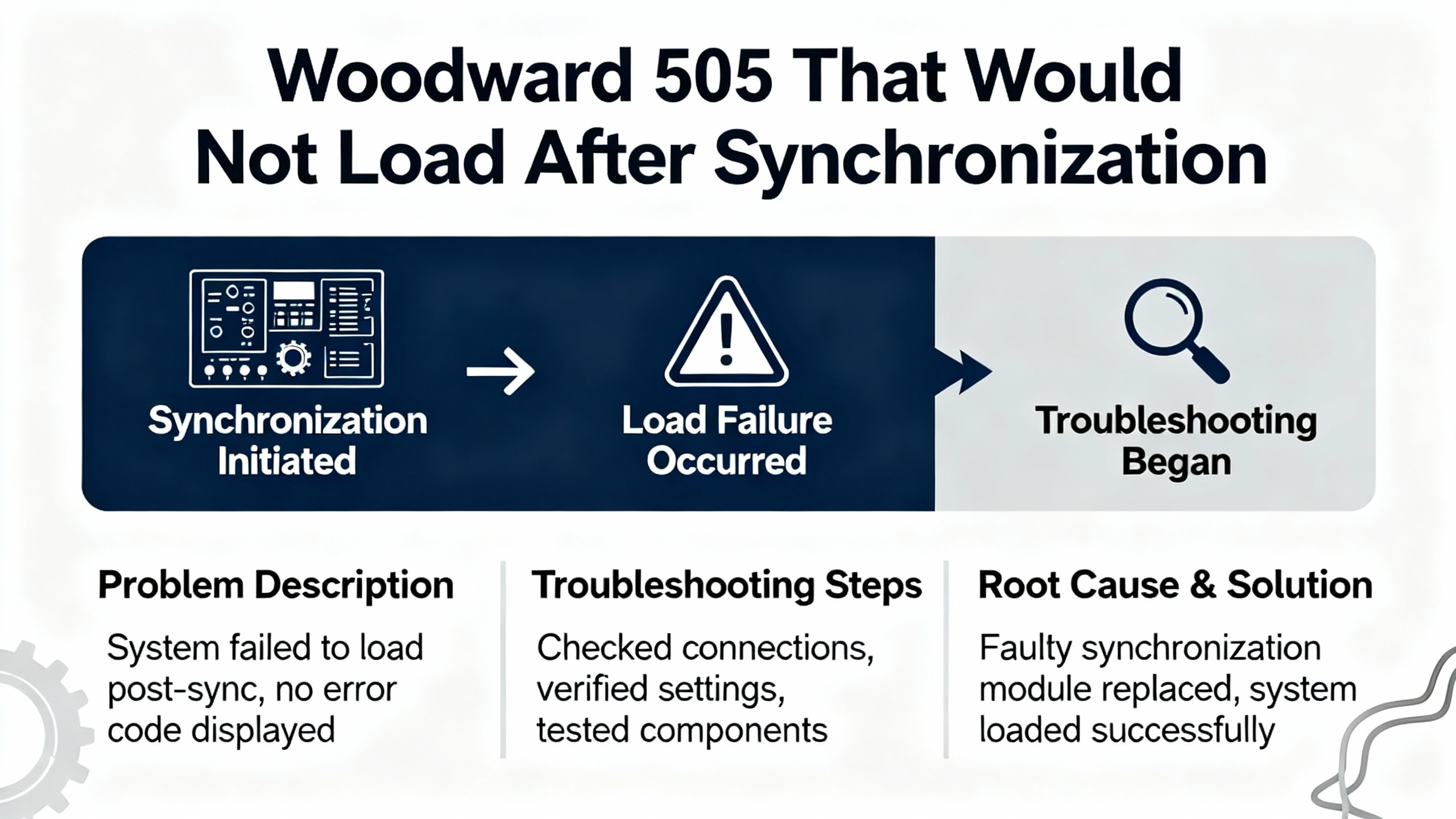
Operators had a steam turbine with a Woodward 505 controlling a generator. After synchronization, when they attempted to raise load, the 505 output signal did not increase as expected. Instead, the controller commanded less opening on the steam control valve and the turbine refused to pick up load. On a later attempt, by aggressively raising the load setpoint to around nine megawatts, the actuator command did rise enough to keep the unit from tripping, but a reverse power relay operated within its delay, keeping the generator online in a marginal state.
The communication chain in this installation was explicit. The 505 produced a 0ŌĆō100 percent demand signal, converted to a 4ŌĆō20 mA current for an electroŌĆæhydraulic governor. That EHG drove a Voith I/H converter, which in turn generated oil pressure to open the steam actuators. There was no valve position feedback wired back to the 505. The plant team had already performed a full stroke test: they used known command signals to move the valves from zero to one hundred percent, confirmed the nonŌĆælinear calibration curve, and verified the valves followed the current and pressure correctly. Hydraulic oil quality was checked and found acceptable.
The crucial diagnostic clue was that, whenever operators requested more load, an internal reference value inside the 505 fell from about thirtyŌĆætwo percent to twentyŌĆætwo percent. The external hardware was faithfully following the controllerŌĆÖs command; the problem was inside the governorŌĆÖs own decisionŌĆæmaking. That points squarely to a communication failure within the control logic: perhaps droop control, limiter logic, or some condition in the 505 that tells it to back away from its reference when certain constraints are violated.
Forum contributors, drawing on experience with Woodward equipment, recommended a methodical strategy. First, use instruments to monitor the EHG output current during static stroking and live loading, building a record of current versus position to confirm there is no hidden nonlinearity or saturation. Second, since the 505 has limited selfŌĆædiagnostics and few user-serviceable components, benchŌĆætest a spare 505, copy configuration parameters from the suspect unit, and swap them. If the spare behaves correctly, the faulty 505 can be sent back to Woodward or a repair shop rather than trying to recalibrate everything downstream.
The key takeaway is that by following the communication path step by step, the team avoided unnecessary replacement of expensive hydraulic hardware and focused on the controller where the internal reference and external command clearly diverged from operator intent.
Having rescued a unit from a communication failure, you naturally want to avoid repeating the experience. The sources referenced earlier offer practical design and maintenance guidance that is well worth building into your standards.
On the electrical side, adopt deliberate wiring practices. Route governor power and signal cables away from highŌĆæcurrent conductors, contactors, and noisy variable speed drives whenever possible. Use shielded or twistedŌĆæpair wiring on power and speedŌĆæsensing circuits as Davidson Sales recommends, and terminate shields correctly. Ensure all terminations are tight, corrosionŌĆæfree, and properly labeled. For systems similar to those described by DieselGeneratorTech, make it part of your commissioning checklist to document sensor and actuator resistance values, mounting gaps, and cable routes so that later troubleshooting has a baseline.
On the control and firmware side, use manufacturer diagnostic tools and recommendations rather than adŌĆæhoc experiments. The A8251ŌĆæ758 guide explicitly calls for connecting to the governor, reading diagnostic codes, addressing communication or firmware issues, and performing firmware updates only as recommended. Calibration procedures should be treated as controlled operations: power on, enter the correct menu, set parameters, verify sensor readings, and test responses to load changes. Once normal speed and gain settings are established, they should not be casually adjusted.
Mechanically, protect your communication chain by maintaining linkages and actuators. Keep the environment around governors and actuators clean and dry. Lubricate moving parts in accordance with manufacturer guidance. Inspect linkages for wear or play and correct misalignment. Mechanical-hydraulic governors and actuator linkages behave exactly like the mechanical components described in RenewableEnergyWorldŌĆÖs general guidance: contamination, varnish, and wear gradually increase deadband and sluggishness, which the control room experiences as communication lag or instability.
From a system perspective, consider how your governors integrate with DCS or SCADA. Digital Woodward governors are usually designed to work comfortably with supervisory controls, as powerŌĆæsystem overviews such as the Fiveable governor guide mention. That integration can include discrete status signals, analog setpoints, or more advanced interfaces. While protocol specifics vary by product and are beyond the scope of the available material, the principle is consistent: any extra layer between operators and governors is another potential communication failure point. Keep interface designs simple, wellŌĆædocumented, and validated, and monitor them with the same rigor as the core governor loop.
Finally, schedule regular functional tests. The A8251ŌĆæ758 article recommends maintenance every six to twelve months, including cleaning, inspection, and response tests. DieselGeneratorTech calls for ongoing maintenance and fault detection. Mechanical governor conditionŌĆæmonitoring guidance suggests periodic step or ramp tests to evaluate dynamic response. Whether your plant runs large steam turbines with Woodward 505 controls or smaller engines with electronic governors, these tests are your best early warning that communication paths are degrading before they fail catastrophically.
No. Based on the troubleshooting patterns summarized from DieselGeneratorTech, Davidson Sales, and the Control.com Woodward 505 case, many apparent communication errors originate outside the controller. Common root causes include open or shorted speed sensors and actuator coils, miswired or noisy signal cables, poor shielding, loose mechanical linkages, and power supply problems. Only after you have verified these items should you suspect an internal governor fault. The Woodward 505 case study is a good example: only after valves, oil, and converters were proven did the team focus on the controller.
The sources around Woodward equipment, especially the 505 discussion, suggest swapping when you have a clear pattern that the governorŌĆÖs internal logic is misbehaving while all external devices are known good. If a digital governor such as a 505 shows internal references moving the wrong way, repeatedly logs communication or firmware errors, fails calibration procedures, or ignores valid inputs even with verified sensors and power, swapping with a knownŌĆægood spare that has the same configuration is a practical diagnostic move. If the problem follows the unit, it should go to Woodward or a qualified repair provider; if the problem stays with the installation, your issue lies elsewhere.
Specialists can help you much faster if you bring structured data rather than just a description like ŌĆ£it will not load.ŌĆØ The case material and troubleshooting guides highlighted here point to several useful items: governor model and firmware revision; recorded alarms and error codes; measured power supply voltage; resistance readings for speed sensors and actuators; confirmation of wiring and shielding practices; results of manual valve or rack stroking tests; and trends of setpoint, actual speed, governor demand, and actuator position if available in your DCS. Having this information ready makes it easier for a Woodward engineer or experienced field technician to identify where the communication chain is breaking.
When a Woodward governor stops communicating effectively with the engine, turbine, or control system, your plant quickly feels the impact. The good news is that these problems are rarely random. By treating the governor, its wiring, its actuators, and its sensors as a single communication chain, and by working through that chain methodically with a meter, a current source, and the manufacturerŌĆÖs tools, you can usually isolate the fault without guesswork. As an onŌĆæsite automation engineer, that is how you keep your units running: verify power, prove the I/O, challenge the controller when the data demands it, and let careful preventive maintenance keep the next ŌĆ£communication errorŌĆØ alarm from ever appearing.


Copyright Notice © 2026 mooreautomated.com All rights reserved,Moore Automated is not an authorized distributor or representative of the manufacturers featured on this website. Brand names and trademarks featured are the property of their respective owners.


Leave Your Comment