

Registered Address: 32D Floor Guomao Building, No.388, Hubin South Road, Siming District, Xiamen,Fujian, China
ISO 9001:2015 Certified
Our quality management system covers sourcing,testing and dispatch
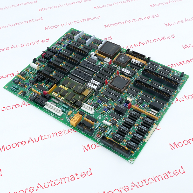
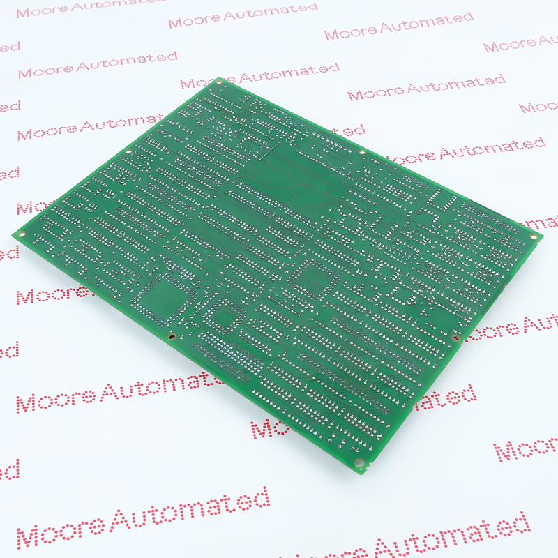
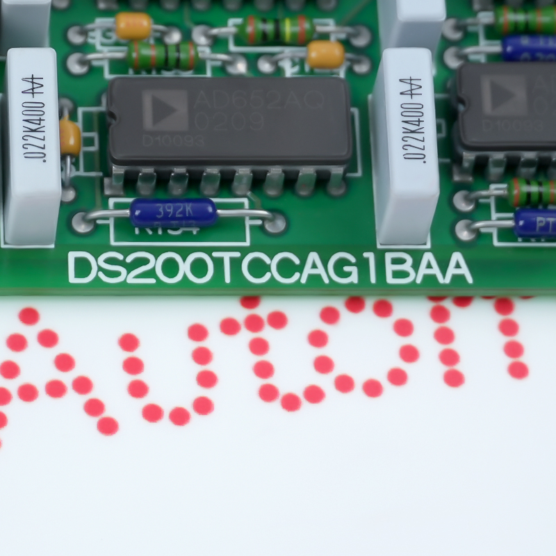
DS215TCCAG1BZZ01A is a GE analog i/o pcb board used within the GE Speedtronic Mark V and Mark VI turbine-control architecture. It provides the specified analog i/o pcb board function while retaining the complete order code, hardware execution and receiving-system compatibility during replacement. Its documented functional acronym is TCCB.
Verify that the supplied item is marked DS215TCCAG1BZZ01A and that its analog i/o pcb board form, connectors and revision agree with the approved GE Mark V and Mark VI Turbine Controls receiving record.
For DS215TCCAG1BZZ01A, state the required condition, quantity, installed position, connected assemblies and document requirements in the written enquiry.
Apply only parameters supported by the exact DS215TCCAG1BZZ01A record or a documented family source. Do not infer electrical ratings or interchangeability from appearance.
DS215TCCAG1BZZ01A technical scope: Functional Acronym: TCCB; PCB Coating: Normal Coating; System Platform: GE Speedtronic Mark V and Mark VI turbine-control architecture; Functional Role: Analog I/O PCB Board function in the documented GE Mark V and Mark VI Speedtronic architecture; Interface Basis: Matching connectors, terminal boards and rack hardware.
Use these values only for the listed hardware execution and verify the supplied label before installation.
Match DS215TCCAG1BZZ01A to the approved GE Mark V and Mark VI Turbine Controls receiving position, connector or terminal arrangement and configuration record.
After power restoration, review diagnostics and test the affected analog i/o pcb board path.
Obsolete/Discontinued by OEM
DS215TCCAG1BZZ01A is a General Electric analog i/o pcb board associated with the GE Mark V and Mark VI Turbine Controls platform. It interfaces the documented field signals with the control system through the assigned channels, terminals and installed I/O position. Correct selection depends on the complete model code, connector or terminal arrangement, hardware revision and receiving-system configuration. Before replacement, compare the original product label, installed slot or cabinet reference, connected assemblies and approved project records. After installation, review system diagnostics and function-test every affected channel, control path, protection function or communication link before returning the equipment to service.

Registered Address: 32D Floor Guomao Building, No.388, Hubin South Road, Siming District, Xiamen,Fujian, China
MooreAutomated.com is the official website and primary online platform operated by Moore Automation Limited. The website provides information about the company’s industrial automation parts sourcing services, product coverage and customer support. Moore Automation Limited operates as an independent supplier and is not an authorized distributor or representative of the manufacturers displayed on this website unless expressly stated.