
Registered Address: 32D Floor Guomao Building, No.388, Hubin South Road, Siming District, Xiamen,Fujian, China
ISO 9001:2015 Certified
Our quality management system covers sourcing,testing and dispatch
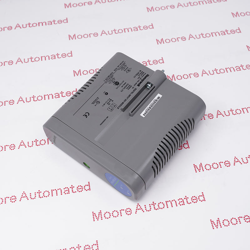
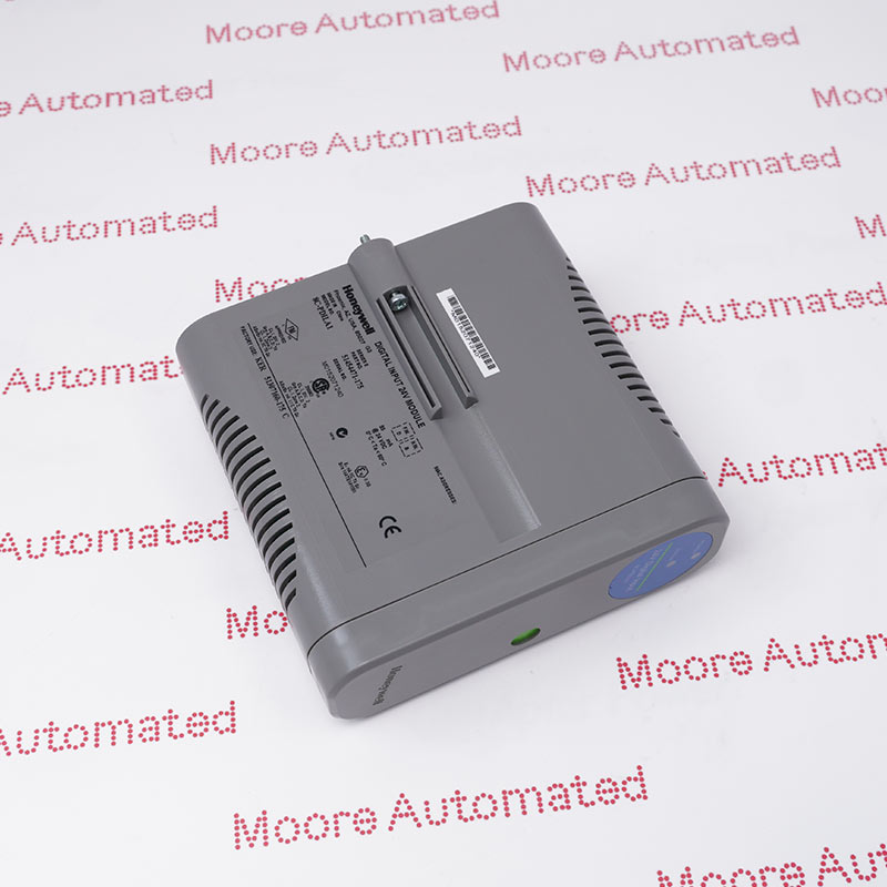
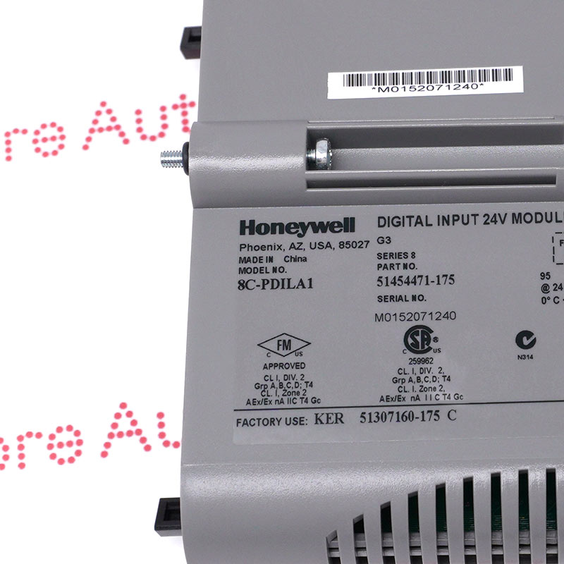
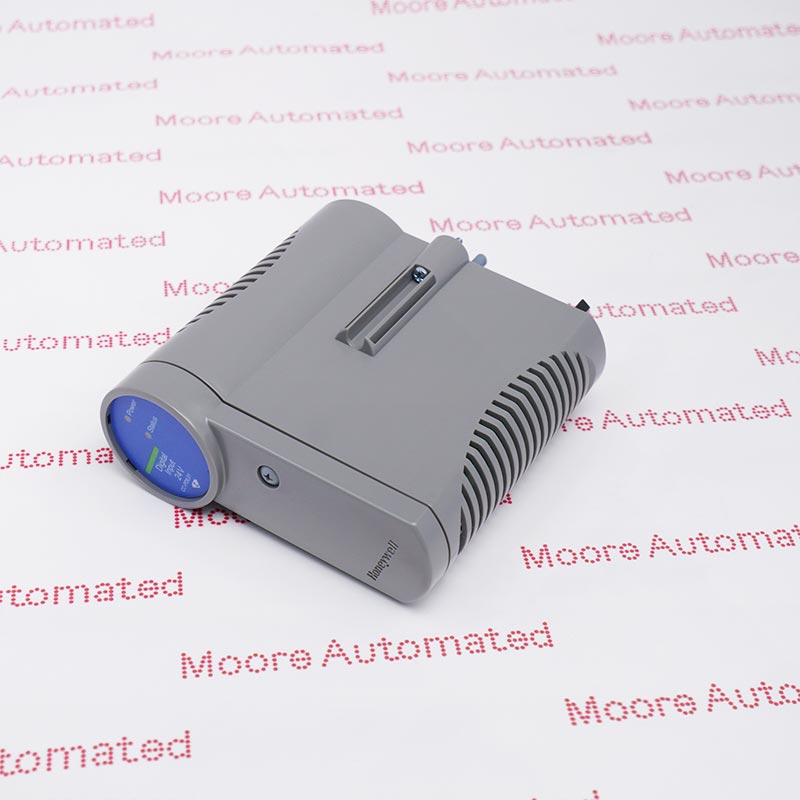
8C-PDILA1 51454471-175 is a Honeywell Series 8 coated 32-channel 24 VDC digital-input module. The manufacturer specification documents optical isolation within the IOM, internal or external field-power selection, defined ON/OFF thresholds and nonredundant or redundant IOTA options. The complete order code, IOTA, field-power method and controller configuration must be matched before replacement.
8C-PDILA1 is the coated Series 8 24 VDC digital-input IOM. Honeywell specifies 32 channels, an 18-30 VDC DI power range, 95 mA module current, 13 VDC or 3 mA minimum ON sensing, 5 VDC or 1.2 mA maximum OFF sensing and 4.2-kilohm input impedance. The module provides direct or reverse indication, internal or external field-power selection, onboard excitation power and optical isolation within the IOM.
The electronic module must be paired with the correct coated termination assembly: 8C-TDILA1 for the nominal 9-inch nonredundant arrangement or 8C-TDILB1 for the nominal 12-inch redundant arrangement. Honeywell specifies 5 ms +/-20% delay across the input filter and isolation and 300-ohm maximum field resistance at 15 VDC for a guaranteed ON condition. These installed-system values do not establish packed dimensions or shipping weight.
Preserve the documented 18-30 VDC field-power range, ON and OFF thresholds, input impedance and filter delay. Confirm whether the installed channels use internal or external field power and whether direct or reverse indication is configured. Record every enabled channel and associated control action before removal.
Match the installed IOTA and redundancy architecture before moving conductors. Use the documented nonredundant or redundant coated termination assembly, then preserve field-power source, polarity, commons, channel numbering, shielding, grounding and terminal assignments. Compare the finished wiring with the approved cabinet drawings before energizing the field circuits.
Back up the controller database and photograph the complete 51454471-175 marking before replacement. After installation, stimulate each authorized input state, confirm configured indication direction, alarms and permissives, inspect channel quality and diagnostics, and prove both electronic paths when the redundant IOTA arrangement is installed.
The module has 32 channels for 24 VDC discrete inputs. Preserve the 18-30 VDC field-power range, documented ON/OFF thresholds, 4.2-kilohm input impedance, optical isolation boundary and 5 ms filter-and-isolation delay. Confirm internal or external field-power selection and direct or reverse indication in the approved project configuration; do not describe this hardware as a 4-20 mA analog input.
Pair the IOM only with the documented coated IOTA arrangement and verify whether the installed cabinet is nonredundant or redundant. Record every terminal and configured channel before removal. After replacement, restore the database, prove each input transition and alarm, check channel diagnostics and verify both module paths when the redundant termination assembly is fitted.


Registered Address: 32D Floor Guomao Building, No.388, Hubin South Road, Siming District, Xiamen,Fujian, China
MooreAutomated.com is the official website and primary online platform operated by Moore Automation Limited. The website provides information about the company’s industrial automation parts sourcing services, product coverage and customer support. Moore Automation Limited operates as an independent supplier and is not an authorized distributor or representative of the manufacturers displayed on this website unless expressly stated.