Registered Address: 32D Floor Guomao Building, No.388, Hubin South Road, Siming District, Xiamen,Fujian, China
ISO 9001:2015 Certified
Our quality management system covers sourcing,testing and dispatch
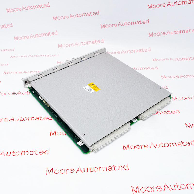
Honeywell's IPC 620-25/35 manual appendix identifies 620-0020 as a 2K (2,048-word) user-program memory module in its superseded-components section. This execution uses a front shorting board for the starting address, not the newer module's DIP-switch method. Match physical label, rack, memory map and program backup.
Honeywell's February 1988 IPC 620-25/35 manual identifies 620-0020 as a 2K (2,048-word) user-program memory module in an appendix covering superseded components. The document notes that such components may still be used in some applications. It states that the module stores the user control program, has a PASS self-test LED and normally occupies slot C in the 620-25 or slot E in the 620-35. The exact capacity is specific to 620-0020; it is not the total system memory capacity.
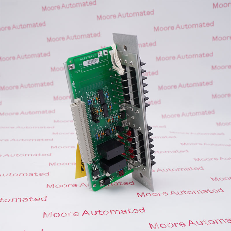
The appendix describes a four-position shorting board at the lower front of the module for setting the starting address. When more modules are used, the memory segments must be arranged in the documented sequence so the processor completes the memory scan. This older method differs from the DIP-switch arrangement described for later memory models in the manual. Before removal, obtain a verified program backup and record every rack position, memory size, address setting and diagnostic indication. Confirm any proposed successor using the full Honeywell compatibility table and site engineering record. After service, restore the approved program and test affected control logic.
The manufacturer appendix lists 620-0020 as 2K (2,048 words) of program memory among superseded components. This older execution should not be conflated with a similarly sized later 620-002x module. Verify the actual board label, shorting board, physical connector and installed rack before procurement or replacement.
Honeywell describes a four-position shorting board on the front of this legacy memory module. It selects the starting address within the controller's memory configuration. The manual's table shows approved sequences for multiple modules. Record the entire installed memory map and shorting-board positions before changing hardware, and avoid gaps or overlapping segments.
The February 1988 Honeywell manual supports exact model identity and capacity but not the current condition, revision or program contents of any stocked item. Its appendix says these components were superseded while still usable in some applications. Current replacement eligibility must be checked against the specific rack and Honeywell compatibility table; a capacity match alone is insufficient.
Confirm 620-0020 on the physical legacy memory module and verify its 2K (2,048-word) capacity. Match the installed IPC 620 rack and primary or option slot, then record the front shorting-board position and full contiguous memory map. The 1988 Honeywell appendix lists this part among superseded components. Do not infer that a later module of equal nominal capacity has identical addressing or direct interchangeability.
Preserve a verified copy of the user control program and record module markings, rack slot, shorting-board position, total memory configuration, PASS indication and processor diagnostics. Follow approved isolation and ESD practice. After installing a verified replacement, restore the documented memory arrangement and program under plant procedures, check module and processor self-tests, and prove affected control functions. Confirm legacy-versus-successor compatibility in manufacturer records before changing module type.

Registered Address: 32D Floor Guomao Building, No.388, Hubin South Road, Siming District, Xiamen,Fujian, China
MooreAutomated.com is the official website and primary online platform operated by Moore Automation Limited. The website provides information about the company’s industrial automation parts sourcing services, product coverage and customer support. Moore Automation Limited operates as an independent supplier and is not an authorized distributor or representative of the manufacturers displayed on this website unless expressly stated.