Get Repair Quote
Name
Company *
Phone *
Email *
Address
City
State / Province / Region
Zipcode
Country
Quantity *
Part Number *
Manufacturer
Preferred Condition
Additional Information
Cancel

IC693PWR321

Standard Power Supply module
In Stock

Product Information:

Standard Power Supply module

that is part of the GE Fanuc Series

90-30 platform. This power supply

has load capacity of 30 Watts with

nominal input voltage of 100 to

240 VAC or 125 VDC

Expand All
Collapse all

Technical specifications for IC693PWR321

  • Manufacturer:
    General Electric
  • Product Category:
    PLC System
  • Estimated shipping dimensions:
    6.6x13x13.5cm
  • Weight:
    0.54 kg
  • Tariff Code:
    8537101190
  • Country of origin:
    USA
  • Place of shipment:
    Xiamen, Fujian, China
  • Product Line:
    Series 90-30
  • Inrush Current:
    4A peak, 250 milliseconds maximum
  • Nominal Rated Voltage:
    120/240 VAC or 125 VDC
  • Input Voltage Range, AC:
    85 to 264 VAC
  • Input Voltage Range, DC:
    100 to 300 VDC
  • Voltage output:
    5/24 Volts DC
  • Communication:
    RS 485
  • Stock:
    30

Revisions

Revision Part #

Also known as

IC693PWR321-CA-A
IC693PWR321--CA-A, Series -CA-A, Rev -CA-A
IC693PWR321-LTAA
IC693PWR321--LTAA, Series -LTAA, Rev -LTAA
IC693PWR321A
IC693PWR321-A, Series A, Rev A
IC693PWR321AA
IC693PWR321-AA, Series AA, Rev AA
IC693PWR321BA
IC693PWR321-BA, Series BA, Rev BA

Information

Overview Manuals Principle

Features:

  • Module of GE Fanuc series 90-30 PLC systems
  • Standard Power Supply module
  • This power supply has load capacity of 30 Watts with nominal input voltage of 100 to 240 VAC or 125 VDC
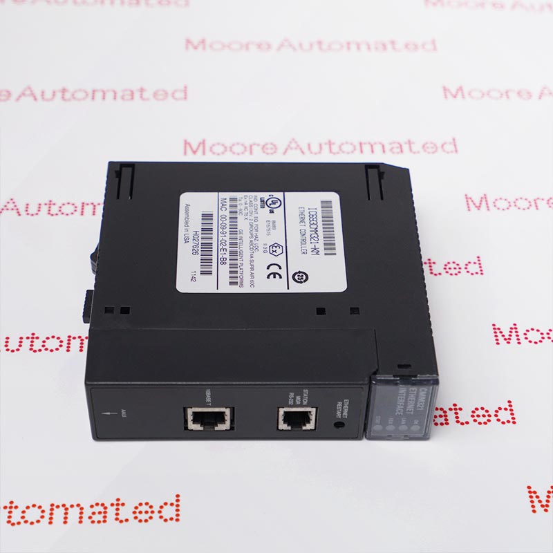
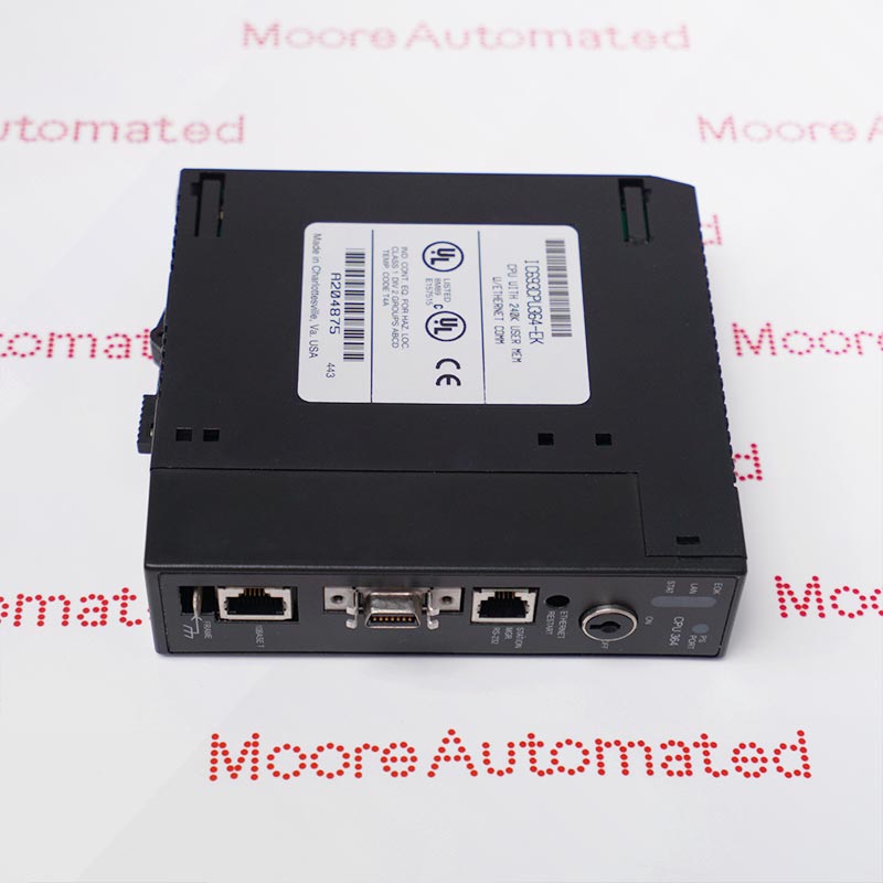
The GE Fanuc IC693PWR321 module is a power module for the 90-30 series, providing power to the processing capabilities of Fanuc 90-30 series PLCs. Located in the leftmost slot on the baseplate, it is rated at 30 watts and is compatible with both AC and DC power supplies. The input voltage range must be between 85 and 264 volts AC or 100 and 300 volts DC.

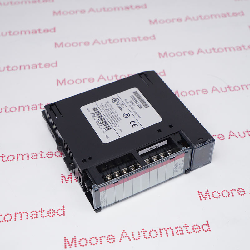
The IC693PWR321 module is fully compatible with all CPU models. This power module is cULus and CE certified and designed for Class 1 Division 2 protection environments. The IC693PWR321 module features current limiting to immediately protect the hardware in the event of a short circuit. The power module is equipped with 6 terminals for operator connection.

The IC693PWR321 GENERAL ELECTRIC Standard Power Supply module may still be available for purchase and support from Moore Automated Company beyond End-Of-Life (EOL) by the manufacturer (OEM).
GENERAL ELECTRIC IC693PWR321 Standard Power Supply module datasheet(manual), Link Important Notice: Other accessories, manuals, cables, calibration data, software, etc. are not included with this equipment unless listed in the above stock item description. All prices are shown in USD.
The IC693PWR321 can be powered by either AC or DC power. Its AC input voltage range is 85-264 VAC, with a nominal value of 120-240 VAC. The DC input voltage range is 100-300 VDC, with a nominal value of 125 VDC. The AC input power requirement is 90 VA, and the DC input power requirement is 50 W. It can withstand a surge current of 4 A peak for 250 ms.

Ask our team:

  • What power conversion topology characterizes IC693PWR321 and how does IC693PWR321 regulate backplane voltage stability?
    The IC693PWR321 is designed as a regulated switching power supply module that converts incoming AC line voltage into stable DC outputs for the Series 90-30 backplane. Through high-frequency switching regulation and feedback control circuitry, IC693PWR321 maintains precise voltage levels required for CPU and I/O module operation.
  • How does IC693PWR321 manage input voltage tolerance and what range of AC supply conditions can IC693PWR321 reliably accommodate?
    The IC693PWR321 is engineered to operate within a specified AC input voltage window, allowing it to tolerate industrial power fluctuations. Its internal rectification and regulation circuitry ensure that IC693PWR321 maintains output integrity despite moderate line disturbances.
  • What output current capacity does IC693PWR321 provide, and how should system designers evaluate load budgeting for IC693PWR321?
    The IC693PWR321 supplies defined current ratings on multiple DC rails used by the backplane. Proper load analysis must account for cumulative consumption of CPU and I/O modules to prevent exceeding the rated current capacity of IC693PWR321.
  • Why is thermal dissipation analysis essential when deploying IC693PWR321 in high-density rack configurations?
    Because IC693PWR321 continuously converts and regulates power, it generates heat proportional to load demand. Adequate ventilation and adherence to ambient temperature limits are essential to ensure long-term reliability of IC693PWR321.
  • How does IC693PWR321 provide protection against overcurrent, short circuit, and overvoltage conditions?
    The IC693PWR321 integrates internal protection mechanisms including current limiting and fault shutdown circuitry. These safeguards protect both the IC693PWR321 module and downstream components from electrical anomalies.
  • How does IC693PWR321 interface mechanically and electrically with the Series 90-30 rack system?
    The IC693PWR321 mounts directly into the designated power supply slot of a compatible rack and connects to the system backplane through integrated connectors. This architecture enables IC693PWR321 to distribute regulated DC power throughout the chassis.
Quantity
Upload
(gif, jpg, jpeg, png, bmp, doc, docx, xls, xlsx, ppt, pdf, csv)
For more information on how your data is processed and stored by Moore automated please read our privacy policy.
Trusted by 5,000+ plants worldwide | Backed by our vast inventory of top-tier control parts, drives and servo motors, fast shipments are dispatched to cover your urgent needs. ABOUT US >>
Moore Disclaimer: Moore Automated's sales automation equipment and related solutions are intended for industrial automation and business operational efficiency improvement purposes only. Product information, technical parameters, and application cases are for reference only and do not constitute an absolute guarantee of performance for any specific industry, scenario, or final application. Actual equipment performance may vary depending on factors such as the usage environment, system integration method, and maintenance conditions. Users should confirm compatibility and safety based on professional technical assessments. Moore Automated assumes no liability for any direct or indirect losses caused by improper use, modification, or failure to operate according to specifications, to the extent permitted by law.