


Registered Address: 32D Floor Guomao Building, No.388, Hubin South Road, Siming District, Xiamen,Fujian, China
ISO 9001:2015 Certified
Our quality management system covers sourcing,testing and dispatch
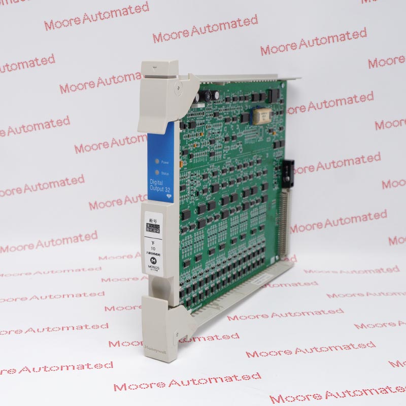
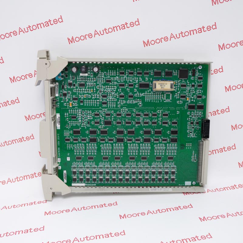
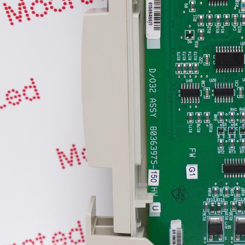
Honeywell maps MC-PDOY22 to CE-compliant part 80363975-150 and lists it as a coated 32-output Digital Output processor. Output voltage and load current depend on the paired transistor or relay FTA; 15-30 VDC applies only to the 24 VDC transistor FTA arrangement. Confirm the installed FTA and load circuit before replacement.
Honeywell's R301.1 guide lists MC-PDOY22 in the Digital Output IOP row with part number 80363975-150. The earlier TPS I/O specification identifies the coated MC model as the 32-output execution. For 24 VDC transistor FTAs MU-TDOY22 and MU-TDOY62, Honeywell lists 15-30 VDC load voltage and current-sinking NPN open-collector outputs. Load-current maxima depend on the chosen FTA and number of energized points, so a single per-channel number is incomplete. The existing page's 0.5 V on-state figure comes from this transistor arrangement, not from every possible relay output configuration.
Honeywell separately lists relay FTAs MU-TDOY23 and MU-TDOY63. Each supports 16 isolated contact circuits; two FTAs and a MU-KBFT01 or MU-KBFT02 bridge cable are required for 17-32 circuits. The relay-contact table varies allowable current with AC or DC voltage and resistive or inductive load. Before replacement, identify FTA model, field loads, suppression and wiring, then follow the manufacturer service procedure and site electrical isolation rules. After an approved change, test every affected output and confirm safe actuator response. Historical technical tables do not establish current lifecycle, universal hot-swap permission or interchangeability among the FTA versions.
Honeywell R301.1 maps MC-PDOY22 to CE-compliant 80363975-150 in its DO IOP row. The TPS I/O model table identifies a conformally coated 32-output processor. Match the complete label and revision against the installed card. Do not substitute MC-PDOX02 or another similar designation based only on a shared digital-output description.
Honeywell specifies 15-30 VDC for the MU-TDOY22/62 transistor FTA configuration, with current-sinking NPN outputs. Relay FTAs MU-TDOY23/63 instead use isolated contacts with separate AC and DC load ratings. The IOP's 32 logical outputs can require two 16-circuit relay FTAs and a bridge cable. Select values from the exact FTA and field-load column, not from a generic module summary.
Record field-load voltage, current, suppression, FTA type, controller assignments and safe actuator states before a controlled exchange. Follow Honeywell's installation instructions and the site's electrical isolation and process-safety plan. After fitting the approved part, confirm diagnostics and test each affected output with the receiving equipment in a safe state. The reviewed documents do not authorize energized replacement or establish current lifecycle status.
Identify whether MU-TDOY22/62 transistor or MU-TDOY23/63 relay termination is installed. Honeywell's transistor table gives a 15-30 VDC load range and FTA-specific point and group current limits. The relay table has separate AC and DC contact ratings, with load type affecting allowable current. Do not apply either table's maximum to the bare MC-PDOY22 processor. Confirm output count, bridge-cable requirement, wiring and suppression against approved drawings before energizing field loads.
Use qualified isolation and the Honeywell service procedure for the installed release. Record existing output states, alarms, FTA model, load details and controller configuration. After installing the approved MC-PDOY22 execution, check recognition, output diagnostics and each affected command path under controlled conditions. Where relay FTAs serve 17-32 circuits, verify both 16-circuit FTAs and the bridge cable. The historical specifications do not establish hot-swap authorization or current lifecycle.

Registered Address: 32D Floor Guomao Building, No.388, Hubin South Road, Siming District, Xiamen,Fujian, China
MooreAutomated.com is the official website and primary online platform operated by Moore Automation Limited. The website provides information about the company’s industrial automation parts sourcing services, product coverage and customer support. Moore Automation Limited operates as an independent supplier and is not an authorized distributor or representative of the manufacturers displayed on this website unless expressly stated.