


3500/32M 149986-02
Get A Quote


Unlocking Industrial Reliability: The Power of the Bently Nevada 3500 Monitoring System
What Makes the Bently Nevada 3500 Monitoring System So Essential?
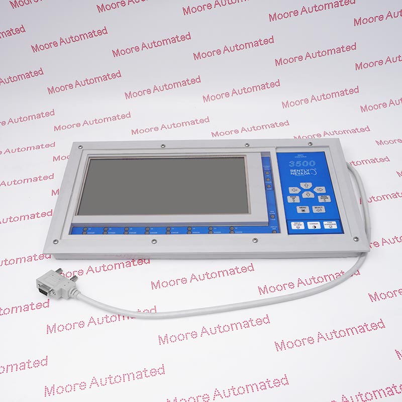
The Bently Nevada 3500 Monitoring System is one of the most widely used and trusted vibration and condition monitoring platforms in the industrial world. Designed by Bently Nevada, a GE company, this system provides continuous online machinery protection and asset condition monitoring for rotating equipment such as turbines, compressors, motors, and pumps.
It plays a critical role in preventing unplanned downtime, reducing maintenance costs, and ensuring the safety and reliability of industrial operations. By offering real-time data on vibration, temperature, and various other parameters, the 3500 system allows engineers to make informed decisions before a minor issue becomes a major failure.
Why Is the Bently Nevada 3500 Monitoring System Vital for Industrial Automation?
In industrial automation and process control, reliability is non-negotiable. The Bently Nevada 3500 Monitoring System acts as the “nerve center” of condition monitoring — continuously tracking machinery health parameters and transmitting data to control systems such as DCS or SCADA platforms.
This capability allows maintenance teams to predict failures, optimize performance, and extend the lifespan of critical assets. It also supports compliance with safety and operational standards, making it indispensable in sectors like oil and gas, power generation, and petrochemicals.
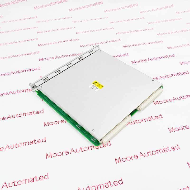
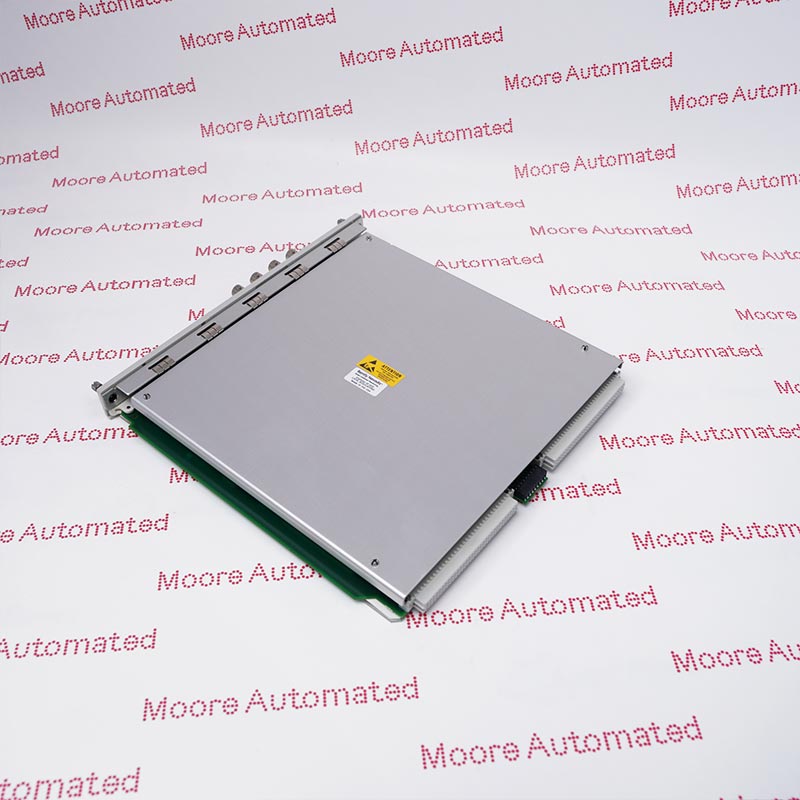
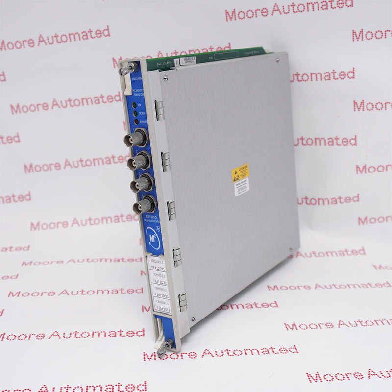
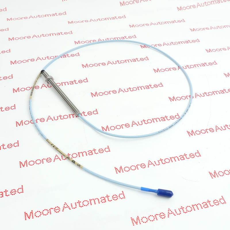
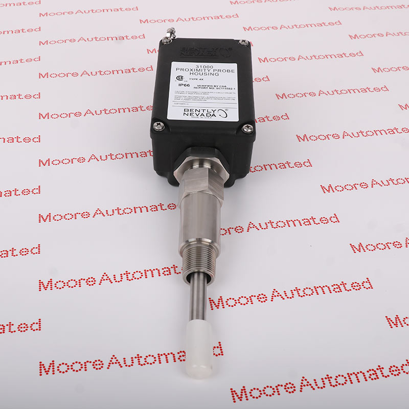
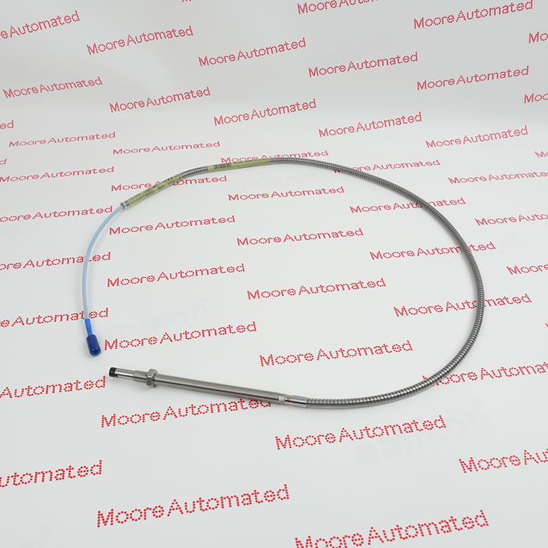
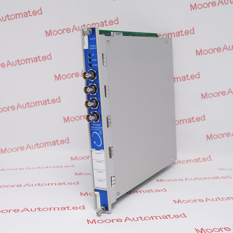
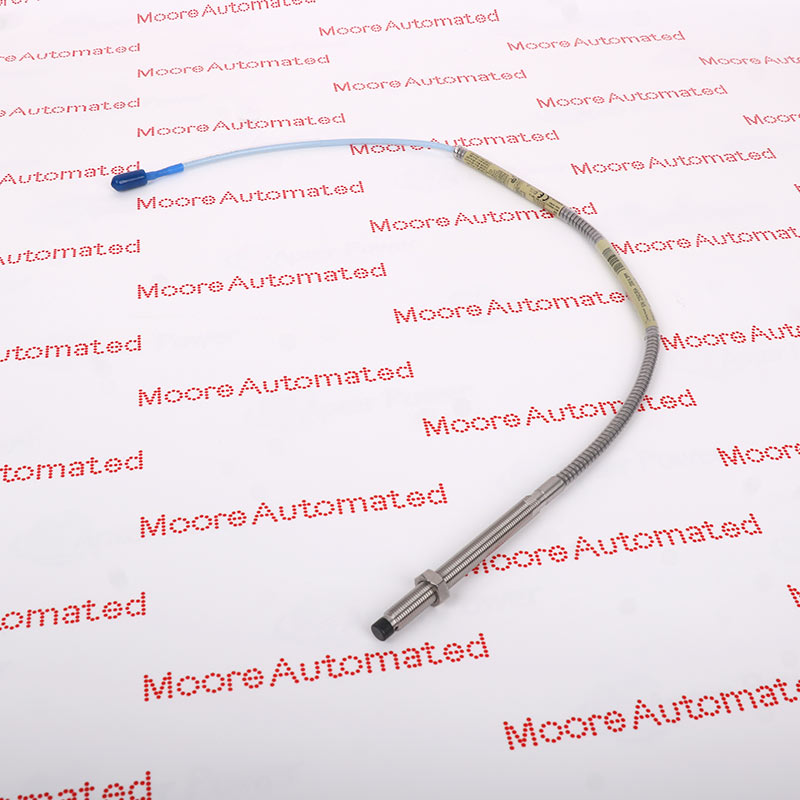
One of the key modules that exemplify this system’s performance is the 3500/42M 176449-02, a dynamic measurement card designed for vibration and position monitoring. The 3500/42M 176449-02 captures data with high precision, enabling real-time diagnostics that are crucial for maintaining equipment integrity. Its flexibility and reliability make it a core component in achieving predictive maintenance strategies.
The 3500/42M 176449-02 integrates seamlessly with other 3500 system modules, providing enhanced functionality such as configurable alarm thresholds, buffered outputs, and compatibility with multiple sensor types. In a typical setup, several 3500/42M 176449-02 modules may be installed across a plant, ensuring comprehensive machinery coverage and data redundancy.
Key Specifications of 3500/42M 176449-02
|
Parameter |
Description |
|
Module Type |
Proximitor / Seismic Monitor |
|
Part Number |
|
|
Input Channels |
4 dynamic channels for vibration or position measurement |
|
Measurement Types |
Radial vibration, axial position, shaft speed |
|
Transducer Compatibility |
Proximity probes, velocity sensors, accelerometers |
|
Sampling Rate |
Up to 20 kHz per channel |
|
Communication Interface |
Compatible with 3500 Rack and System Communications Module |
|
Power Consumption |
Approx. 10 W |
|
Alarm Functions |
Configurable alert and danger thresholds |
The 3500/42M 176449-02 not only provides precise measurement and control capabilities but also enhances plant safety and operational insight through advanced signal processing and flexible configuration options.
How to Install the 3500/42M 176449-02
Installing the 3500/42M 176449-02 requires careful handling and adherence to safety procedures. Here’s a simplified overview of the process:
Prepare the Rack:
Ensure the Bently Nevada 3500 rack is powered off before installation. Verify that the slot designated for the 3500/42M 176449-02 is clean and free of dust or debris.
Insert the Module:
Gently slide the 3500/42M 176449-02 into its slot until it firmly connects with the backplane connector. Secure the module using the provided screws or locking tabs.
Connect Sensors:
Attach proximity probes or vibration sensors to the input terminals according to the wiring diagram in the installation manual. Double-check polarity and grounding.
Configure the Module:
Using the Bently Nevada Configuration Software, set up parameters such as measurement range, alarm thresholds, and channel types.
System Verification:
Power on the system and confirm that the 3500/42M 176449-02 communicates correctly with the rack and displays readings accurately.
Calibration and Testing:
Perform initial calibration and functional testing to ensure all sensors and alarms operate as expected.
By following these steps, engineers can ensure that the 3500/42M 176449-02 operates optimally and contributes effectively to overall machinery protection and monitoring.
Recommended models
|
175Z0043 |
S5 24VDC 2 N/O 2 N/OT |
355-3SD00 FM355 R355 |
|
FX5UC-32MT/DSS-TS |
0100-3L-0012-4-HVAC |
FHF21225107 |
|
MDX61B0008-5A3-4-0T |
MINI MCR-SL-UI-2I-NC |
WL12-2N430 |
|
KU-BF1 |
3G3EV-AB007MA-CUES1 |
CRT1-5820 B2 |
|
AS-J892-101 |
R88D-KN04H-ECT-Z |
MC07B0008-2B1-4-00 |
|
CIMR-V7AZ40P70 |
OPTD3’╝øPC00261 |
DFE33B |
|
175Z0040 |
ESC-C13 V1.60 |
440E-A13080 |
|
EPC-PM-BOX |
5SM2622-2 |
HC16-F-H01-S3.03-SM11-ZL10 |
|
MC07B0030-5A3-4-00 |
AK403-114,0 |
WTR2-P521 |
|
IQ80-60NPP-KK0 |
AL2-10MR-A |
MCC101A2K5T3E20A |
|
CJ1W-AD04U |
FX2N-32MT-ESS/UL |
PTQ-PDPMV1 REV. 1.0 |
|
200 S-DIAS |
PZ-G61CP |
70CMR00267 |
|
NX1P2-9024DT |
MC07A005-5A3-4-00 |
X3 24VAC 24VDC 3N/O 1N/C 1SO |
|
MC07B0008-5A3-4-00 |
3KA5030-1GE01 |
E6D-CWZ2C |
|
FP25T |
3G3MV-A4007 |
ST121USBHD |
|
GS4200-V001AB |
82407381-001 |
AC100V 50/60 HZ RS232C |
|
60/EB-TA |
MM03D-503-00 |
CJ1M-CPU11-ETN |
|
FX3U-485ADP-MB |
A413281 |
BKDR-46-0045 |
|
CV500-LK201 |
MAS51A005-503-00 |
CP25QXVT80 |
|
SI-N1/V7 |
51305437-100 |
MDS60A0015-5A3-4-00 |
|
8/8 - INTERBUS |
UM18-21112B211 |
3G3EV-A2001M |
|
PCS095 |
SR-X100W |
VKR1 C1 69-000-399 |
|
T119 |
CIMR-V7CC44P0 |
WL12G-3B2531 |
|
GLCA01A1B |
NT31-ST121B-EV1 |
FX3U-48MR/DS |


Copyright Notice © 2026 mooreautomated.com All rights reserved,Moore Automated is not an authorized distributor or representative of the manufacturers featured on this website. Brand names and trademarks featured are the property of their respective owners.
Leave Your Comment