Overview
Manuals
Typical Deployment
Wiring Considerations
Signal Performance
Features:
- Provides four isolated 4–20 mA inputs together with four isolated 4–20 mA outputs.
- Maintains electrical isolation between the field/system interface and between individual I/O channels.
- Supports dual-redundant installation for control architectures requiring increased I/O availability.
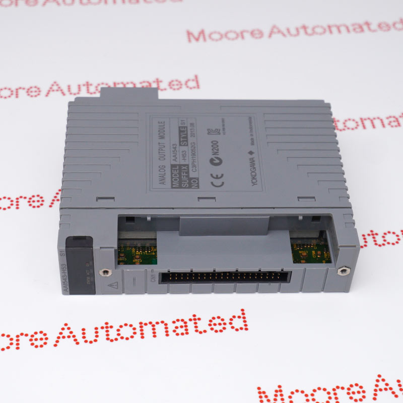
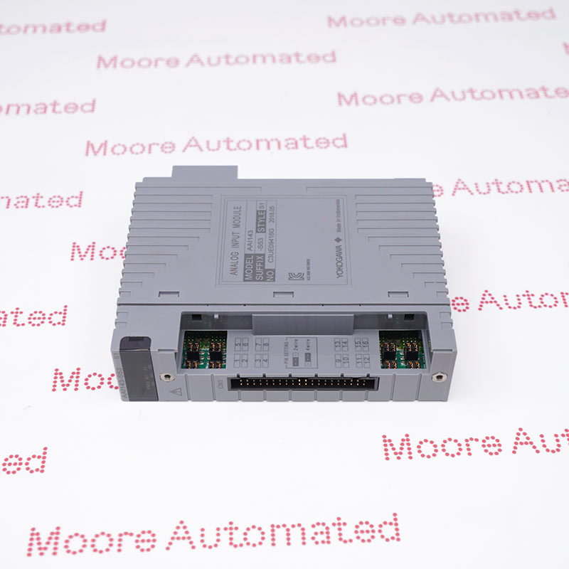
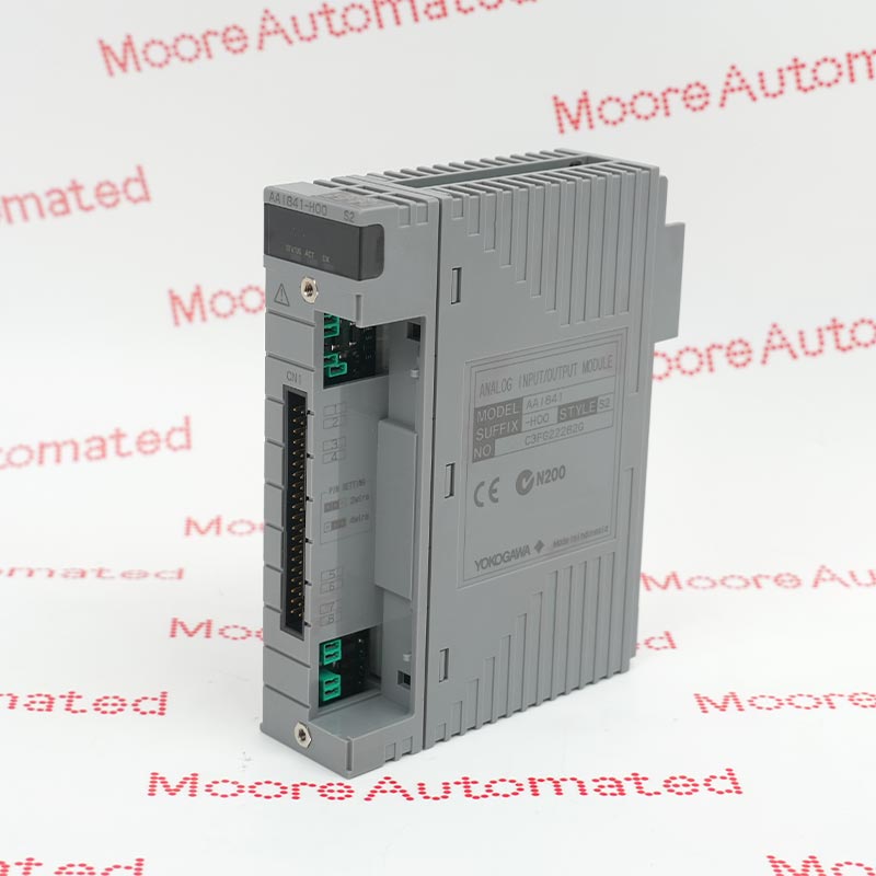
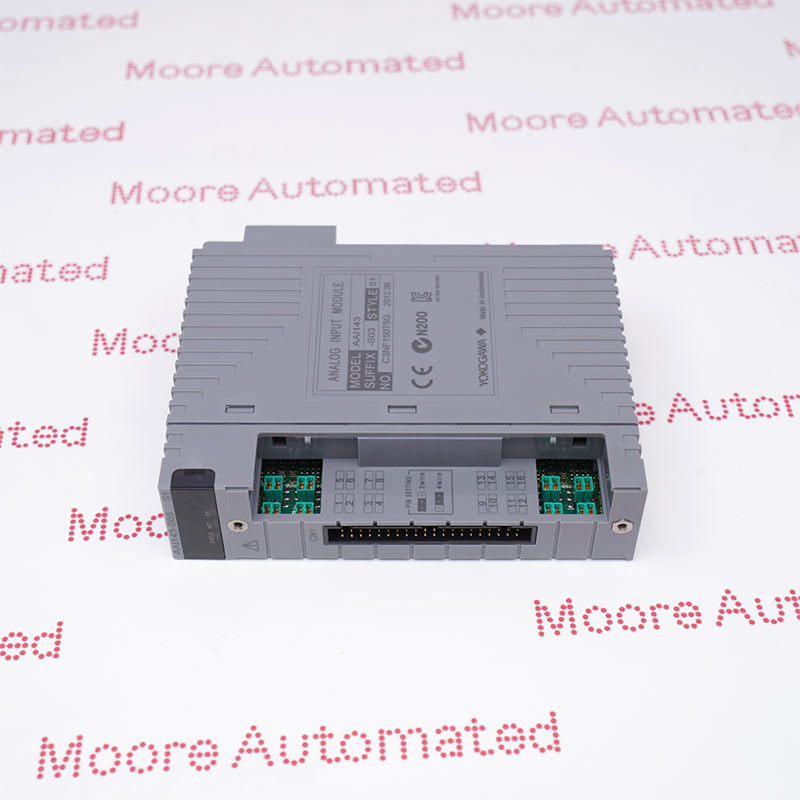
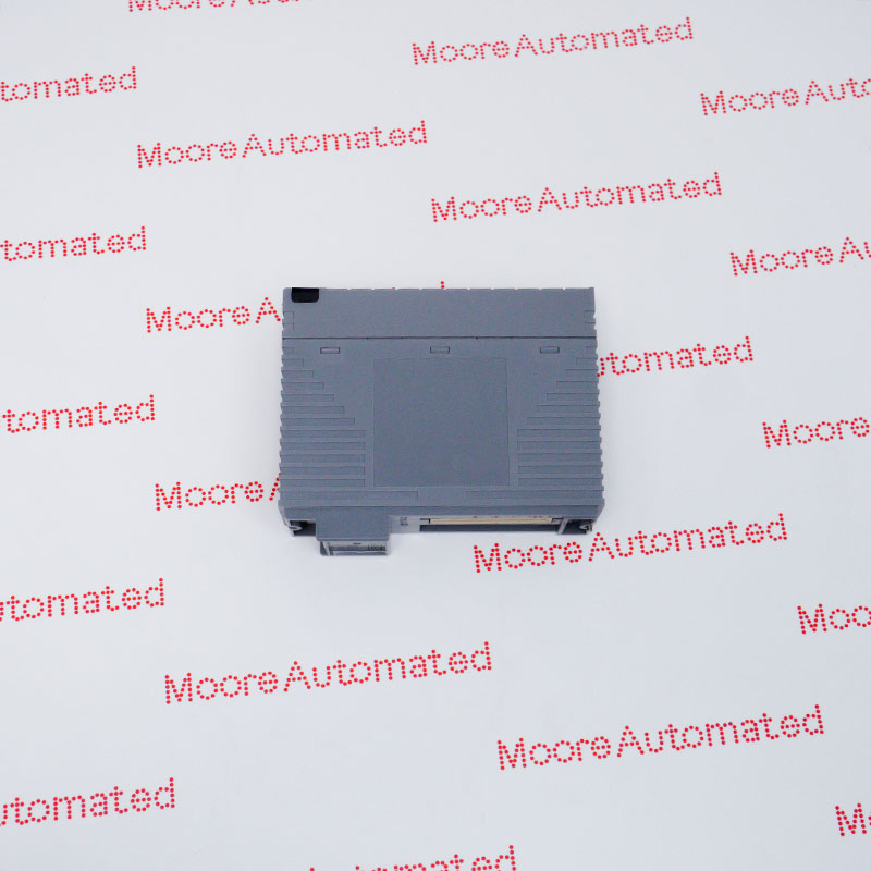
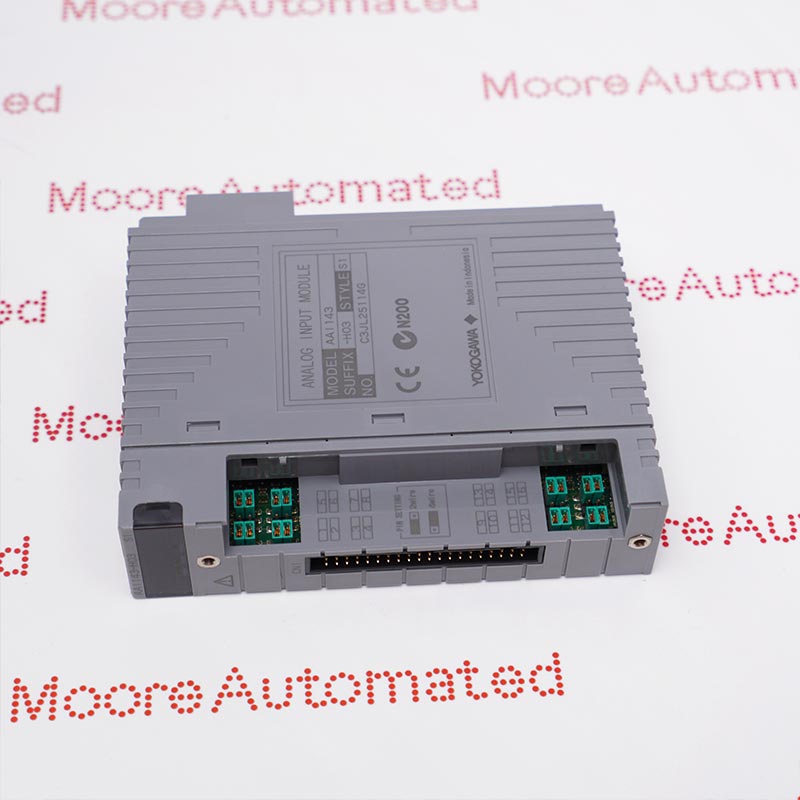
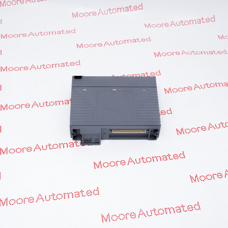
The Yokogawa AAI835-S00 S2 belongs to the AAI835 series of isolated current I/O modules designed for use in Yokogawa control systems based on the FIO architecture. This module features four input channels and four output channels, all operating within the 4–20 mA signal range. It provides a withstand voltage of 500 V AC (for one minute) between the I/O circuits and the system, as well as between the individual I/O channels.
The AAI835 can be integrated into Yokogawa's FIO I/O architecture through the configuration of appropriate terminals and cables. Depending on the specific connection scheme, Yokogawa's connection documentation specifies the dedicated input terminals (IN1A–IN4A, IN1B–IN4B, and IN1C–IN4C) and output terminals (OUT1+–OUT4+ and OUT1−–OUT4−).
The AAI835-S00 S2 YOKOGAWA Analog I/O Module may still be available for purchase and support from Moore Automated Company beyond End-Of-Life (EOL) by the manufacturer (OEM).
YOKOGAWA AAI835-S00 S2 Analog I/O Module official technical documentation and verified Moore Automated resources.
Important Notice: Confirm the complete model, article number and installed configuration before replacement. All links open in a new page.
The AAI835 is intended for Yokogawa FIO applications where isolated 4–20 mA measurement and control signals must be exchanged between field instrumentation and the control system. Its four input and four output channels allow the same module to handle both analog signal acquisition and analog signal transmission within the applicable Yokogawa control architecture.
When installing an AAI835, the field wiring should be matched to the Yokogawa-defined terminal arrangement rather than treating the module as a generic 4–20 mA I/O device. The official connection data identifies separate terminals for the four input channels and four output channels, and specific wiring arrangements are provided for 2-wire transmitters and current-input applications. The existing terminal blocks, cables and signal configuration should therefore be checked before replacing the module.
For engineering calculations, the manufacturer's 0–750 Ω allowable output load, ±16 μA input accuracy, ±48 μA output accuracy, and 10 ms update period should be considered when assessing the receiving equipment and control-loop performance. The input circuit has a specified resistance range of 290 Ω at 20 mA to 450 Ω at 4 mA, which should also be considered when checking transmitter loop loading and compatibility.