Overview
Manuals
Physical Structure
How It Works
Features:
- Input status indicators
- Two isolated groups of 8 with voltage supervision
- 16 channels for 24 V d.c. inputs with current sinking
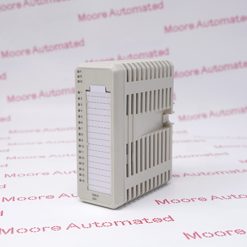
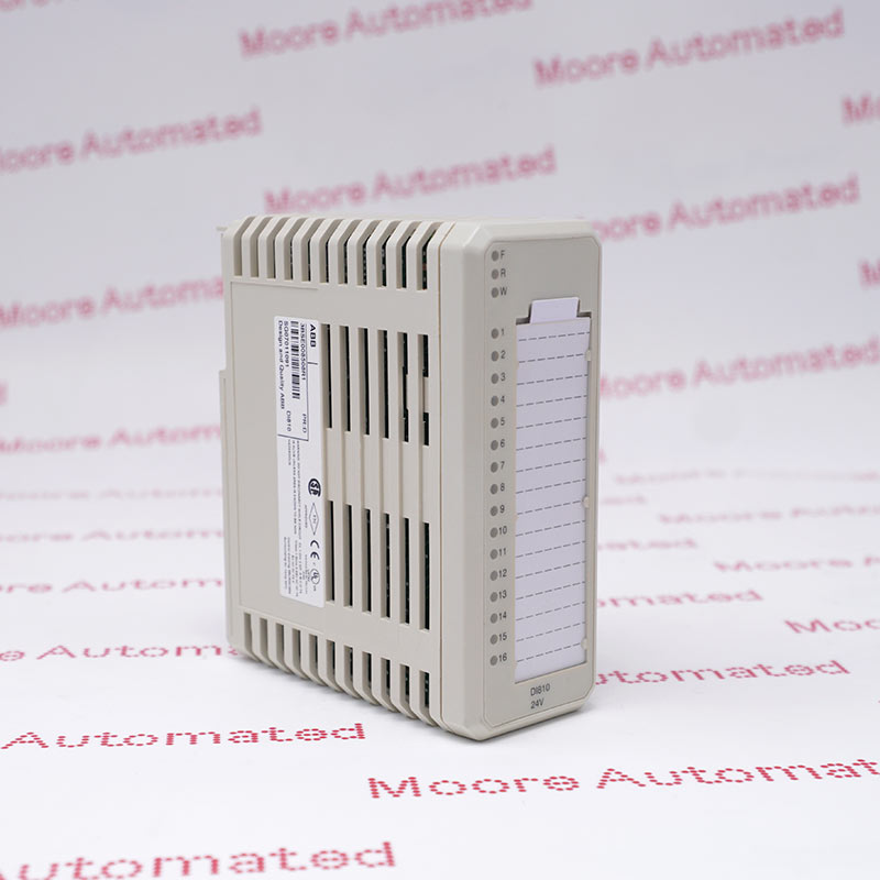
This module has 16 digital inputs. The input voltage range is 18 to 30 volt d.c. and the input current is 6 mA at 24 V. The inputs are divided into two individually isolated groups with eight channels and one voltage supervision input in each group. Every input channel consists of current limiting components, EMC protection components, input state indication LED and optical isolation barrier. The process voltage supervision input give channel error signals if the voltage disappears. The error signal can be read via the ModuleBus.
This module offers 16 independent digital input channels, specifically designed for acquiring various switching signals (such as the on/off states of pushbuttons, limit switches, pressure relays, proximity switches, etc.) in industrial environments. Its rated input voltage is 24V DC (operating voltage range 18 to 30V DC), and it features current absorption design, enabling large-scale status monitoring of complex automated production lines.
The DI810 3BSE008508R1 ABB Digital Input Module may still be available for purchase and support from Moore Automated Company beyond End-Of-Life (EOL) by the manufacturer (OEM).
ABB DI810 3BSE008508R1 Digital Input Module manual(Datasheets), Link
Important Notice: Other accessories, manuals, cables, calibration data, software, etc. are not included with this equipment unless listed in the above stock item description. All prices are shown in USD.
1. Multi-level fault self-diagnosis: Each channel is equipped with an independent field status LED indicator and an opto-isolation barrier. More importantly, each group is equipped with a dedicated process voltage monitoring input. If the external sensor process power supply is interrupted or the entire group is powered off, the module will immediately send a channel error alarm to the main controller via the ModuleBus internal bus, and the F (fault) red indicator light on the front of the module will also illuminate.
2. Adapter base and mechanical foolproof design: The card itself is a passive plug-in component (net weight only 0.15 kg) and cannot be wired independently. It must be inserted into a dedicated terminal unit base (MTU) to be used and is fully compatible with the S800 series expansion bases, including TU810, TU812, TU814, TU818, TU830, TU833, TU838, and TU850. Its factory physical mechanical key code is fixed at AA. Combined with the base's foolproof design, it ensures that other module models will not be mistakenly inserted during system hot-swappable maintenance.
Electrical Isolation and Bus Data Transmission: During operation, an external field switch closes to disconnect the circuit and inputs a 24V DC high-level signal to the DI810's input channel. This current signal first passes through the module's internal current-limiting components and electromagnetic compatibility (EMC) protection circuitry to eliminate high-frequency noise interference. Subsequently, the signal undergoes photoelectric conversion through an optical isolation barrier, safely transmitting the signal to the internal logic circuit while completely severing the electrical connection between the field high voltage and the internal microprocessor. The microprocessor within the module filters and scans the status of each channel (filtering time selectable at 2, 4, 8, or 16 milliseconds), encapsulates it into digital status data, and finally transmits it at high speed to the main controller via the ModuleBus internal bus on the base (e.g., TU810, TU812 terminal base).