Overview
Manuals
Applications
Critical Field Installation Remotes
Features:
- Bently Nevada 7200 Series (commonly paired with older 3300 or 9000 Monitoring Systems)
- Designed specifically for a combined system length of 5 meters (16.4 feet) (total electrical length of probe and extension cord)
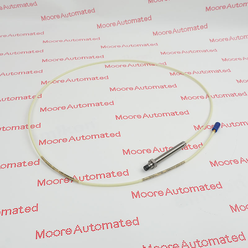
- Works interchangeably with 5 mm and 8 mm non-contacting proximity probes
The 5 mm and 8 mm systems use the same type of Proximitor. Both 5 and 9 metre Proximitors are available. A threeconductor, shielded cable provides the signal output and power source input between 7200 Proximitors and Bently Nevada monitors. Proximitors can be located up to 1,000 feet from standard Bently Nevada monitors without degradation of performance.
The 7200 5 mm and 8 mm Proximity Transducer Systems are noncontacting, gap-to-voltage transducer systems that measure static as well as dynamic distances between the probe tip and the observed target. The general application is any requirement for an accurate, noncontacting displacement measurement. However, the most common use is for shaft position and vibration measurements on rotating and reciprocating machinery.
The 18745-03 Bently Nevada Proximitor may still be available for purchase and support from Moore Automated Company beyond End-Of-Life (EOL) by the manufacturer (OEM).
Bently Nevada 18745-03 Proximitor Manuals(Datasheets), Link
Important Notice: Other accessories, manuals, cables, calibration data, software, etc. are not included with this equipment unless listed in the above stock item description. All prices are shown in USD.
The 7200 5 and 8 mm Systems have a frequency response of 0 Hz (DC) to 10 kHz and can be used to make the following types of measurements:
• Radial vibration for indicating bearing condition and such machine malfunctions as rotor imbalance and misalignment.
• Axial thrust position for determining thrust bearing wear or potential bearing failure.
• Shaft average radial position, for determining attitude angle, an indicator of rotor stability.
• Vibration amplitude and phase angle for plotting diagnostic information in Polar and Bode formats.
• Eccentricity to measure the amount of rotor bow.
System Compatibility: The -03 module must be used with an electrical system of 5 meters in total length. Using a 9-meter probe or an incompatible extension cable will result in significant linear calibration errors.
Gap Voltage Adjustment: During actual installation, the engineer must adjust the physical gap distance until the initial bias output voltage is at the linear midpoint (typically around -10V DC) before locking the probe.