



Registered Address: 32D Floor Guomao Building, No.388, Hubin South Road, Siming District, Xiamen,Fujian, China
ISO 9001:2015 Certified
Our quality management system covers sourcing,testing and dispatch
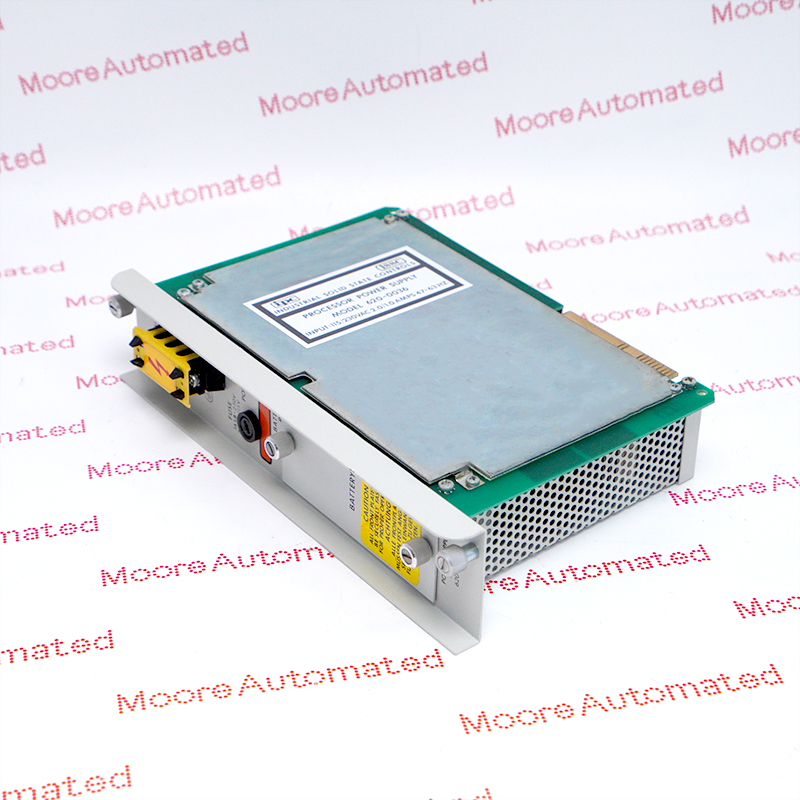
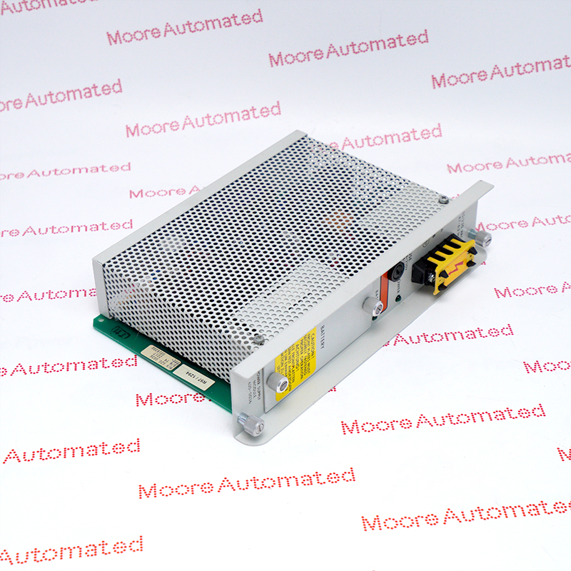
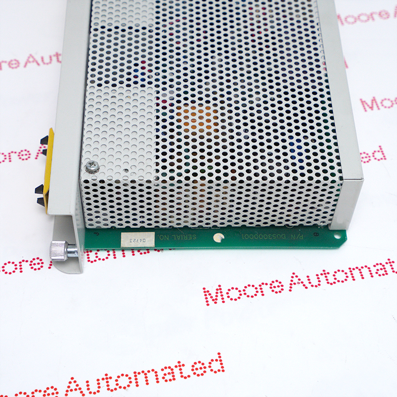
Honeywell's IPC 620-25/35 manual identifies 620-0036 as a processor power supply module with user-selected 115 or 230 VAC input. It occupies two rack slots and includes a memory-backup battery compartment. Match the installed rack, AC selection, fuse, hardware revision and full marking before replacement.
Honeywell's IPC 620-25/35 User Manual identifies 620-0036 as the AC-input processor power supply module, distinct from 24 VDC-input 620-0047. It mounts in H/I of the 620-25 or J/K of the 620-35 and powers the processor rack. The manual describes a lithium battery for memory and register backup, a front POWER indicator and a BATTERY PASS indicator. It states a 15 A maximum +5 VDC supply for processor-rack modules and 300 mA of +12 VDC for optional equipment. Those ratings should be checked against the actual installed rack loading.
The manual says a yellow shorting board inside the side cover selects 115 or 230 VAC and documents 2 A slow-blow fuse use for 115 VAC versus 1 A for 230 VAC. A 1988 manual is not a substitute for current electrical safety requirements, plant isolation practice or item-specific inspection. Record the incoming supply, selector, fuse, processor rack, battery state, cable terminations and diagnostics before work. Preserve program and data backups. After a verified replacement, confirm voltage selection and wiring under qualified procedures, restore power in the approved sequence and verify controller diagnostics and memory retention.
The Honeywell manual identifies 620-0036 as a processor power supply accepting user-selected 115 or 230 VAC. It is not the 24 VDC-input 620-0047. The module occupies two rack positions, H/I in the 620-25 and J/K in the 620-35. Confirm exact label and rack before obtaining a spare.
Honeywell describes a yellow shorting board beneath the side cover for AC voltage selection. It documents a 2 A slow-blow fuse for 115 VAC operation and a 1 A slow-blow fuse for 230 VAC. These are manual-era technical details, not permission to work energized. Qualified personnel must check incoming power, selector, fuse and current safety procedure before energizing.
The supply houses a lithium memory-backup battery and provides processor-rack DC power. The manual quotes a maximum 15 A at +5 VDC and 300 mA at +12 VDC. Verify actual rack loading and battery condition, protect control-program and data backups, and confirm the POWER and BATTERY PASS indications after replacement under approved site practice.
Confirm 620-0036 on the physical processor supply, the receiving IPC 620-25 or 620-35 rack and the two-slot fit. The Honeywell manual documents user-selected 115 or 230 VAC input, a yellow voltage shorting board and input-specific slow-blow fuses. Record and verify the actual plant supply, selector and fuse before energizing. Its DC output limits are specified for the documented rack; compare actual module load rather than assuming any configuration fits.
A qualified technician should save a verified controller program and data backup, record wiring, rack loading, battery status, selector position and original diagnostics, then isolate and test for absence of hazardous voltage under current site procedures. Inspect the replacement and its battery and connectors. Reconnect and energize only after checking approved AC selection and fuse. Validate POWER and BATTERY PASS indications, controller self-tests, I/O behavior and memory retention. Follow current Honeywell and local electrical-safety requirements.

Registered Address: 32D Floor Guomao Building, No.388, Hubin South Road, Siming District, Xiamen,Fujian, China
MooreAutomated.com is the official website and primary online platform operated by Moore Automation Limited. The website provides information about the company’s industrial automation parts sourcing services, product coverage and customer support. Moore Automation Limited operates as an independent supplier and is not an authorized distributor or representative of the manufacturers displayed on this website unless expressly stated.