

Registered Address: 32D Floor Guomao Building, No.388, Hubin South Road, Siming District, Xiamen,Fujian, China
ISO 9001:2015 Certified
Our quality management system covers sourcing,testing and dispatch
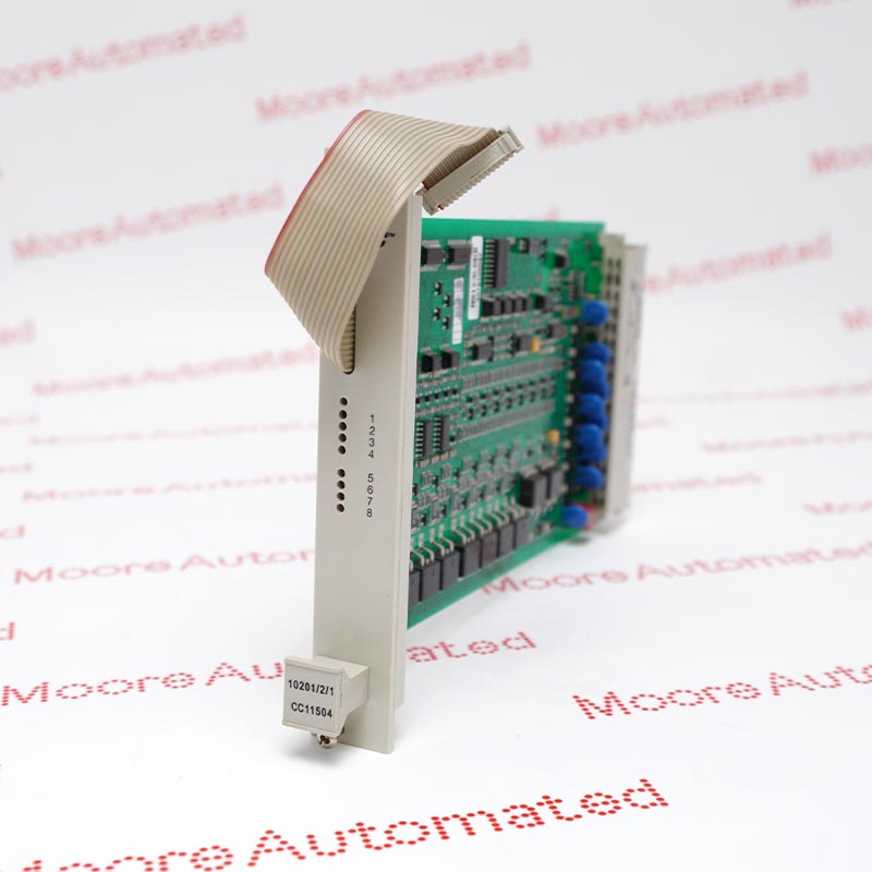
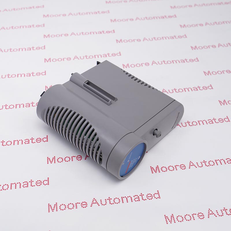
Honeywell's Experion PKS FTE Bridge Implementation Guide names TK-FTEB01 in its chassis installation procedure. The reviewed excerpt does not validate the separate 51309512-175 order number or detailed ratings; check the supplied nameplate and applicable system documentation before ordering or installation.
The reviewed Honeywell Experion PKS Release 515 implementation-guide excerpt identifies TK-FTEB01 in an FTE Bridge installation heading. It describes aligning the module circuit board with the upper and lower guides of the planned chassis slot, and says the chassis should already be installed and grounded with power not applied for the illustrated insertion procedure. Slot 0 is typically reserved for the communication module, but the selected slot must be verified against the specific chassis plan. The excerpt does not supply an electrical rating or complete network configuration.
For procurement or replacement, compare the complete TK-FTEB01 nameplate and the additional 51309512-175 number with a Honeywell parts record and the installed bill of materials. Confirm chassis hardware, approved release, network topology and configuration in the full Honeywell documentation. Before disturbing a live control system, qualified personnel should follow the site's process-safety, isolation and change-management rules. After fitting the exact approved module, use the complete guide to configure and verify bridge communications and affected control paths before restoring normal service.
The reviewed Honeywell guide explicitly names TK-FTEB01, while the page's additional 51309512-175 number is not present in that excerpt. Inspect the physical marking and verify the order number against a manufacturer parts record before treating them as the same procurement execution. Do not infer substitution from the separately named TC-FTEB01 model.
Honeywell's cited section assumes an already installed and grounded chassis with power not applied. It instructs the installer to align the module circuit board with the upper and lower chassis guides at the planned slot; the guide says slot 0 is typically reserved for the communications module. Use the full installation guide for the remaining steps and site-specific controls.
The excerpt confirms the FTE Bridge designation but omits port count, cable topology, IP setup, software release matrix and diagnostic acceptance criteria. Obtain the applicable complete Honeywell implementation guide and approved system drawings before changing any network path. Record the existing configuration and demonstrate restored bridge health and affected control communications after authorized service.
Follow the Honeywell guide and site authorization for the exact installed release. The reviewed section assumes that the chassis is installed and grounded and that power is not applied while following its insertion procedure. It illustrates alignment of the module circuit board with the top and bottom chassis guides in the planned slot. Do not treat the excerpt as the complete lockout, wiring or commissioning procedure.
Before replacement, record the full module marking, additional order number, chassis location and existing bridge/network state. Obtain the complete manufacturer implementation guide to check compatible releases, required configuration, connection details and diagnostics. Following approved installation, verify module identification and communication recovery for all affected paths under site test procedures. The reviewed excerpt alone does not establish port specifications or hot-swap capability.

Registered Address: 32D Floor Guomao Building, No.388, Hubin South Road, Siming District, Xiamen,Fujian, China
MooreAutomated.com is the official website and primary online platform operated by Moore Automation Limited. The website provides information about the company’s industrial automation parts sourcing services, product coverage and customer support. Moore Automation Limited operates as an independent supplier and is not an authorized distributor or representative of the manufacturers displayed on this website unless expressly stated.