


Registered Address: 32D Floor Guomao Building, No.388, Hubin South Road, Siming District, Xiamen,Fujian, China
ISO 9001:2015 Certified
Our quality management system covers sourcing,testing and dispatch
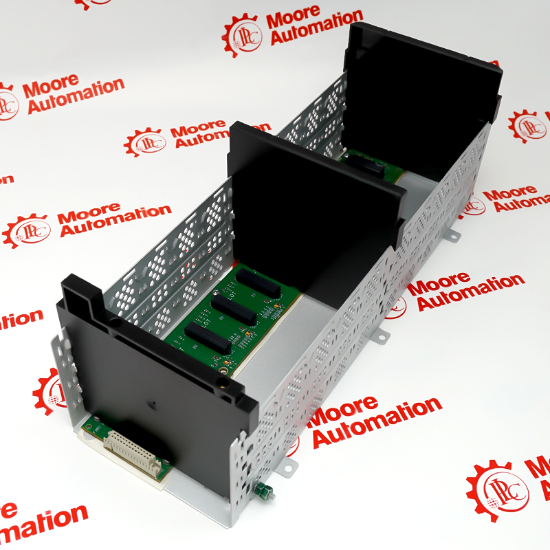
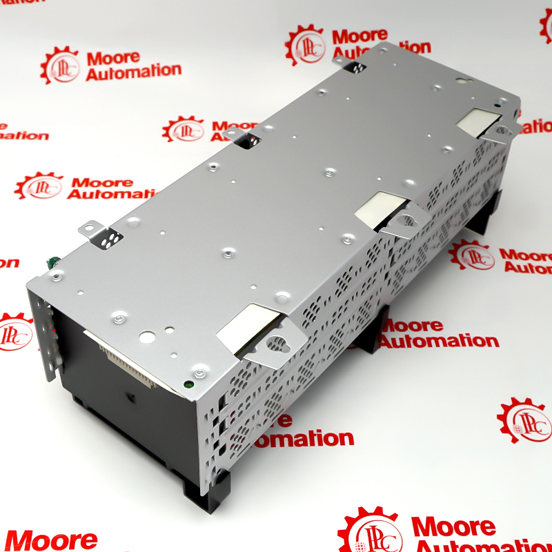
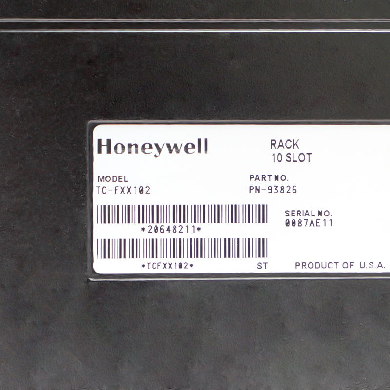
TK-FXX102 is a Honeywell ten-slot, 13 A conformally coated chassis for Experion Series A Chassis I/O. It provides the mounting positions and backplane for compatible controller, communication and I/O modules in a C200/C200E-based installation. It is not an input module or a standalone power supply. The selected chassis power supply mounts at the left without using an I/O slot; field-device power and the installed module load must be assessed separately.
The TK-FXX102 supplies the physical rack and electrical backplane for a Honeywell Experion Series A Chassis I/O assembly. It offers ten module positions and is identified by Honeywell as the coated 13 A chassis execution. Compatible control, communication and I/O modules connect through this backplane, while a separate chassis power supply mounts on the left. The chassis is therefore infrastructure for the installed system, not an input interface that independently acquires measurements, and its current designation is not a field-signal range.
A replacement must preserve the established slot allocation, module widths, power arrangement and cabinet mounting. Check total rail loading against the selected power supply rather than treating the 13 A chassis designation as an unconditional output rating. The manufacturer lists a specific adapter for redundant power and gives minimum cabinet clearances for installation. Conformal coating does not remove the need for a suitable enclosure or environmental control. Honeywell's January 2023 notice names this exact chassis among the Series A parts entering Phase-out on 31 January 2023; availability and an engineered migration plan should be considered separately.
The chassis has ten module positions. Single-width and double-width modules use one and two positions respectively, so usable I/O capacity depends on the actual controller, communication and I/O layout. A chassis power supply mounts at the left without occupying an I/O slot. Include every installed module in the supply-loading assessment and keep field-device power separate from backplane loading.
Honeywell distinguishes this 13 A chassis generation from earlier 10 A chassis. The redundant-power compatibility table explicitly lists TC-RPSCA2 or TK-RPSCA2 for TK-FXX102. This establishes the adapter pairing, not the contents of a supplied spare chassis. Select the complete supply arrangement against the installed architecture and manufacturer instructions; the chassis does not itself accept a declared universal 16–32 VDC input.
TK identifies the conformally coated execution. Honeywell's Series A guidance still requires appropriate cabinet protection and installation conditions. Panel mounting calls for at least 152 mm vertical and 102 mm horizontal clearance to cabinet boundaries, with 203 mm vertical separation between chassis and at least 203 mm enclosure depth. Check the actual mounting outline because the source's two dimension tables use different height figures.
Prepare an as-installed slot map before requesting a replacement chassis, including module labels, occupied widths, cable destinations and any redundant-power hardware. Identify whether the quoted item is the bare chassis or an assembly with power equipment; photographs alone do not establish that accessories are included. Keep the current module configuration and identification records with the maintenance package so that rack work does not unintentionally change the control-system arrangement.
Plan chassis replacement as controlled cabinet maintenance with the affected equipment safely isolated under the site's approved procedure. Module-level removal-under-power provisions must not be interpreted as permission to replace the chassis while energized. Before restoring service, inspect mounting, protective grounding, connectors and cable routing, then verify module recognition and system diagnostics against the recorded installation. Resolve any dimensional discrepancy using the actual hardware and approved installation drawing before work begins.

Registered Address: 32D Floor Guomao Building, No.388, Hubin South Road, Siming District, Xiamen,Fujian, China
MooreAutomated.com is the official website and primary online platform operated by Moore Automation Limited. The website provides information about the company’s industrial automation parts sourcing services, product coverage and customer support. Moore Automation Limited operates as an independent supplier and is not an authorized distributor or representative of the manufacturers displayed on this website unless expressly stated.