Overview
Manuals
Principle
Features:
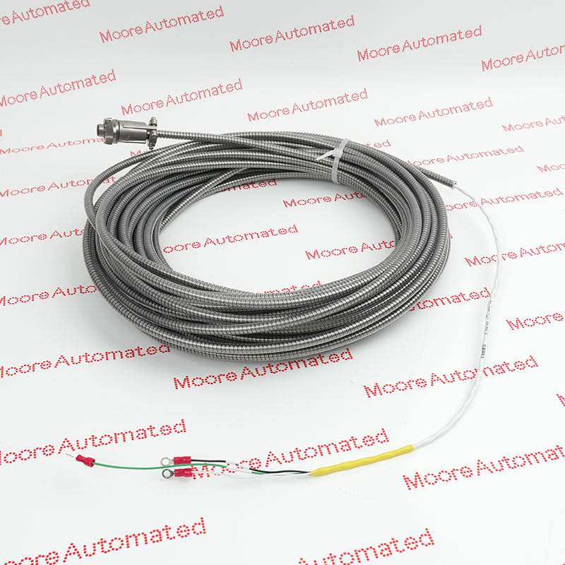
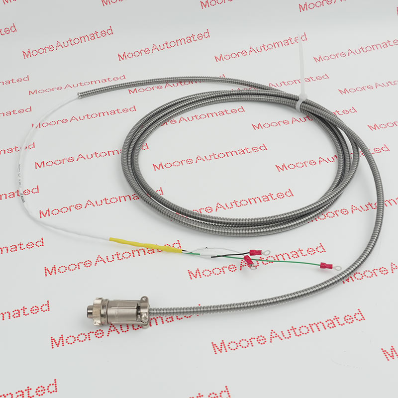
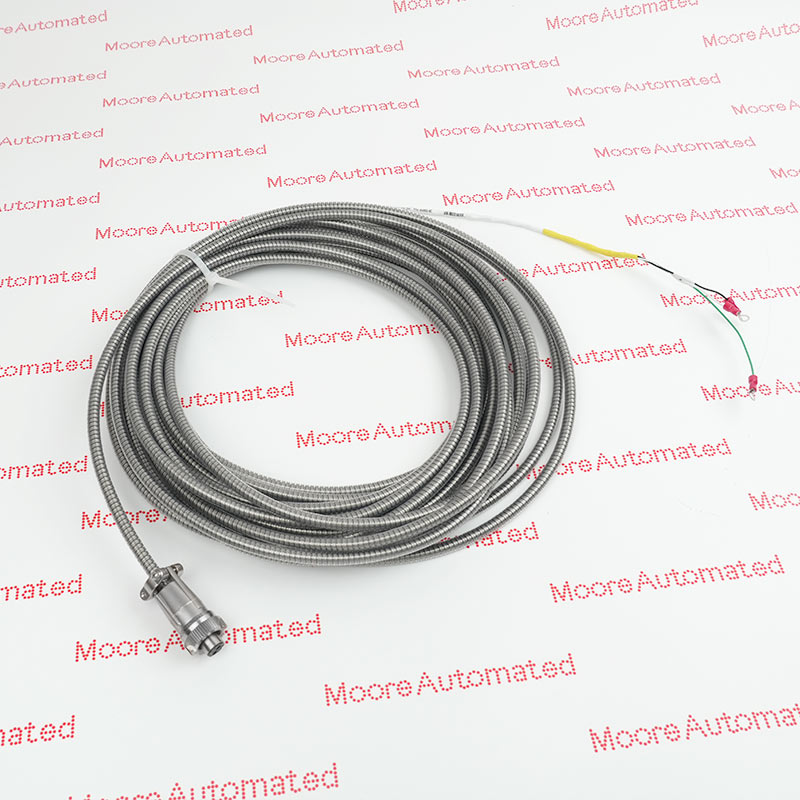
- 330425 Accelerometer
- 330400 and 330425 Accelerometer Acceleration Transducers
- It provides an amplitude range of 50 g peak and a sensitivity of 100 mV/g
These accelerometers are intended for critical machinery applications where casing acceleration measurements are required, such as gear mesh monitoring. The 330400 is designed to address the requirements of American Petroleum Institute Standard 670 for accelerometers.
It provides an amplitude range of 50 g peak and a sensitivity of 100 mV/g. The 330425 is identical except it provides a larger amplitude range (75 g peak) and a sensitivity of 25 mV/g.
The 330425-01-05 Bently Nevada Accelerometer Acceleration Transducers may still be available for purchase and support from Moore Automated Company beyond End-Of-Life (EOL) by the manufacturer (OEM).
Bently Nevada 330425-01-05 Accelerometer Acceleration Transducers Manuals(Datasheets), Link
Important Notice: Other accessories, manuals, cables, calibration data, software, etc. are not included with this equipment unless listed in the above stock item description. All prices are shown in USD.
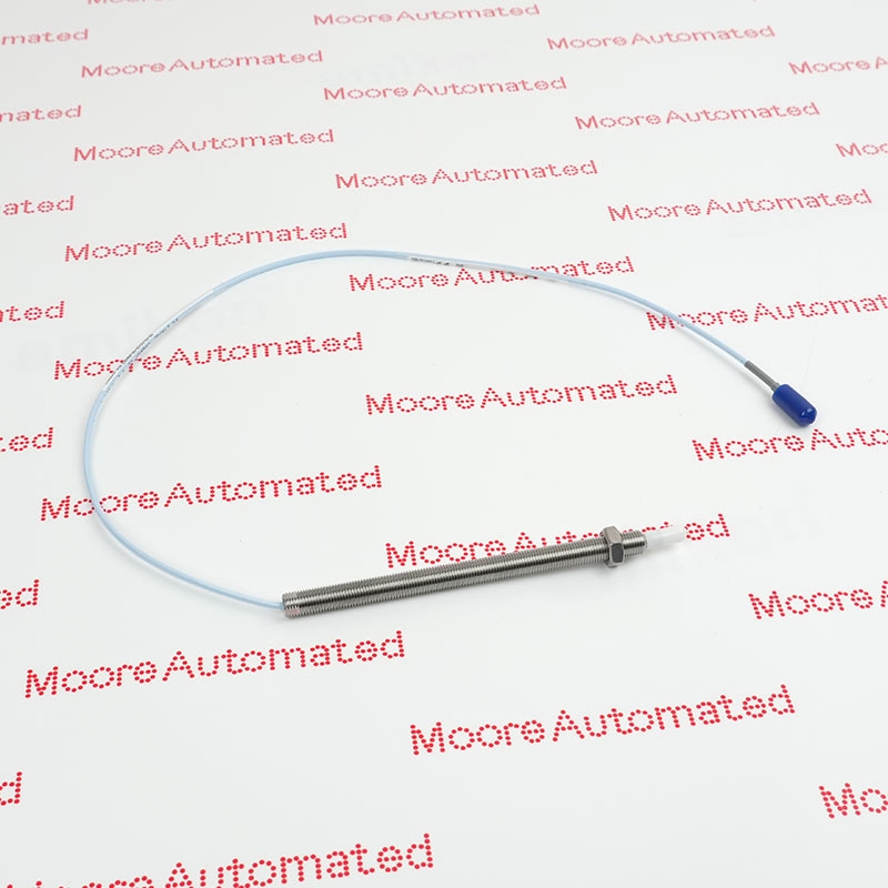
Its working principle involves using a high-frequency oscillator to generate an electromagnetic field at the probe tip. When the probe approaches a conductive target surface (such as a rotating shaft), the magnetic field induces eddy currents in the target material. Changes in the gap distance between the probe and the target alter the intensity of the induced eddy currents, thereby modulating the oscillator signal. This modulated signal is converted into a proportional electrical signal output, providing precise displacement or vibration data for real-time, accurate monitoring in industrial machinery applications.